EP1382959A1 - Reflexionsphotometrisches Analysesystem - Google Patents
Reflexionsphotometrisches Analysesystem Download PDFInfo
- Publication number
- EP1382959A1 EP1382959A1 EP03014002A EP03014002A EP1382959A1 EP 1382959 A1 EP1382959 A1 EP 1382959A1 EP 03014002 A EP03014002 A EP 03014002A EP 03014002 A EP03014002 A EP 03014002A EP 1382959 A1 EP1382959 A1 EP 1382959A1
- Authority
- EP
- European Patent Office
- Prior art keywords
- analysis system
- target surface
- distance
- light
- axis
- Prior art date
- Legal status (The legal status is an assumption and is not a legal conclusion. Google has not performed a legal analysis and makes no representation as to the accuracy of the status listed.)
- Granted
Links
Images


Classifications
-
- G—PHYSICS
- G01—MEASURING; TESTING
- G01N—INVESTIGATING OR ANALYSING MATERIALS BY DETERMINING THEIR CHEMICAL OR PHYSICAL PROPERTIES
- G01N21/00—Investigating or analysing materials by the use of optical means, i.e. using sub-millimetre waves, infrared, visible or ultraviolet light
- G01N21/84—Systems specially adapted for particular applications
- G01N21/8483—Investigating reagent band
-
- G—PHYSICS
- G01—MEASURING; TESTING
- G01N—INVESTIGATING OR ANALYSING MATERIALS BY DETERMINING THEIR CHEMICAL OR PHYSICAL PROPERTIES
- G01N21/00—Investigating or analysing materials by the use of optical means, i.e. using sub-millimetre waves, infrared, visible or ultraviolet light
- G01N21/17—Systems in which incident light is modified in accordance with the properties of the material investigated
- G01N21/47—Scattering, i.e. diffuse reflection
- G01N21/4738—Diffuse reflection, e.g. also for testing fluids, fibrous materials
Definitions
- the invention relates to a reflection photometric Analysis system with one radiation source and one Radiation detector comprehensive measuring head for reflectometric Examining one at a distance from that Measuring head arranged target surface of a test object, especially a test strip for body fluids like urine or blood.
- the invention relates a corresponding measurement method.
- JP-A 03-166738 (Publication number 10948/1993) already a sensor for distance measurement and a control unit for Setting the measuring distance suggested. There is however nothing about the functional principle of distance detection disclosed. The general problem is that the surface properties of test strips by applying sample liquid can fluctuate greatly, since both almost dry, rough surfaces as well as wet and therefore shiny Surfaces can exist.
- the invention is based on the idea of a change the measuring distance by a corresponding change in the beam path to be detected with spatial resolution. Accordingly according to the invention is an optical one Triangulation working triangulation unit for non-contact Check the distance of the measuring head to the Target surface provided. With this, the influence of Height variations of the target surface in a simple way can be eliminated without reducing the efficiency of the photometric Measuring system would be affected. There can be any and in particular completely diffuse reflective measuring points are scanned on the target surface become.
- the triangulation process has one high distance resolution and can with positioning movements work largely in real time.
- the triangulation unit advantageously has one aimed at the target surface in an axis of incidence Light transmitter and one in the direction of a receiving axis light receiver pointing towards the target surface on. It is for reference measurements favorable if the axis of incidence and reception converge a reference point at a given angle intersect, the reference point being a target position the target surface.
- the axis of incidence and reception different from a solder on the target surface include angles.
- the light deflection correlated with the change in distance grasping sees a preferred implementation before that the light receiver is transverse to the receiving axis has spatially resolving sensor.
- a PSD sensor Position Sensing Detector
- CCD sensor Charge Coupled Device
- multi-element diode sensor Find application can be a PSD sensor (Position Sensing Detector), CCD sensor (Charge Coupled Device) or multi-element diode sensor Find application.
- the light receiver has as a double sensor two preferably symmetrical arranged side by side to the receiving axis Individual sensors, especially individual diodes. This allows distance variations through resulting Detect lighting differences between the individual sensors.
- the light receiver with its optical axis Collecting optics defining the receiving axis for bundling of the light reflected from the target surface
- the light transmitter is a light source, in particular a point light source and one with its optical Collimator optics defining the axis of incidence to generate one on the target surface has incident light beam.
- the light transmitter has a modulation level for time-varying, preferably pulse-shaped Control of a light source. So that one can Tolerance compensation of the reflectance improved and the detection electronics are simplified. Therefor it is favorable if the light transmitter has an edge generator to generate non-linear, preferably exponentially rising or falling light pulses having.
- the triangulation unit advantageously has a signal processing circuit for determining Distance changes from a reference position the target surface. To change position on a To be able to reduce the time measurement, it is an advantage if the signal processing circuit is a comparator and a timer for determining the temporal Distance of predetermined signal amplitudes from output signals of the triangulation unit.
- Triangulation unit interacting control device to set a predetermined distance between Target surface and measuring head by means of an actuator in front.
- An additional benefit can be achieved in that the travel path of the measuring head by means of a distance measuring device to determine a height profile of the test object is detectable, and that the path measuring device a height profile memory to identify the Has test object.
- the triangulation unit is an evaluation unit to standardize the photometric test results according to the distance between the target surface and measuring head is downstream.
- the above is Task solved in that the measuring distance of the measuring head to the target surface using a triangulation unit based on optical triangulation is checked without contact.
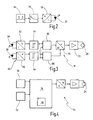
- the reflection photometric shown in the drawing Analysis system essentially consists of one Measuring head 10 for the reflectometric examination of the Target surface 12 of an analytical test strip 14, a triangulation unit 16 for testing or recording the measuring distance between measuring head 10 and target surface 12 and a control device 18 for adjustment a constant measuring distance.
- the test strip 14 different test fields 20 that are more specific to the detection Analytes in a body fluid to be examined, for example urine or blood.
- the measuring head 10 can be attached to one Carriage 22 by means of a feed drive 24 in Strip direction move while the photodetector 26 of a photometer from the target surface 12 of the Test fields 20 reflected light detected. It can via an actuator 28 of the control device 18 constant measuring distance between photodetector 26 and target surface 12 of the test fields of different thickness 20 can be set.
- To record the travel path of the measuring head 10 are on the rotating spindles Drives 24, 28 angle sensors sensitive to the direction of rotation 30, 32 arranged. These deliver with a rotary movement Counting pulses, from which according to the A linear path can be calculated.
- the triangulation unit 16 has a light transmitter 34, which is also the radiation source 36 for the forms reflectometric measurement.
- the light transmitter 34 comprises a semiconductor diode 38 as a light source and a collimator lens 40 for generating a direction an axis of incidence 42 on the target surface 12 directed light beam.
- the triangulation unit has light beams 16 a light receiver 48 through a collecting optics 44 and a double diode sensor consisting of two single diodes 46 is formed.
- the collection optics 44 defines with its optical axis a receiving axis 50, which coincides with the axis of incidence 42 in a reference point 52 cuts, whereby a target position of the Target surface 12 is determined.
- the individual diodes 46 are symmetrical to the receiving axis 50 side by side arranged and point with their receiver surface against the target surface 12 so that in the target position both individual diodes 46 illuminated with the same intensity are.
- the light source is 38 can be controlled in a pulsed manner by means of a generator circuit.
- This includes a modulation level 54 for determination the pulse intervals, an edge generator 56 for generating exponentially falling light pulse edges and a voltage-to-current converter 58 for Power supply to the light source 38, the light intensity follows the course of the current pulses.
- the output signals of the Light receiver 34 via a downstream signal processing circuit 60 in the sense of a further below described distance control can be evaluated.
- the individual diodes 46 are each one Current-voltage converter 62 and a threshold comparator 64 with a timer 66 and a phase comparator 68 connected.
- a subordinate integrator level 70 sets the time difference of one Comparator signals assigned to light pulse with correct sign into a corresponding voltage signal. This can be used as a control signal for an analog amplifier stage 72 supplied to control the actuator 28 become.
- the one shown in FIG. 3 forms Circuit the control device 18, which during the measurement compliance with the various test fields 20 the reference position or a specified measuring distance ensures.
- the path detection system 74 shown in FIG. 4 enables it, the test strip 14 based on the height profile identify his test fields 20. For that be the counting pulses of the angle sensors 30, 32 in a microcontroller 76 counted to the current position or the travel of the measuring head 10 starting from a To determine the starting position. Due to the distance control results when the feed drive is actuated 24 an elevation profile with the stored data be compared in a height profile memory 78 can, if necessary, about the validity of the measurement to decide.
- a distance measurement is generally based on triangulation on the comparison of similar triangles that according to the beam path as an object triangle between Object and converging lens and as an image triangle between Collection lens and receiver can be unclamped.
- the method is based on relative measurements limited to a reference plane, whereby by changing the distance of the imaging point of the Test object (diffuse) reflected detection light the receiver surface is deflected accordingly.
- the spatial deflection can be caused by pulse modulation of the detection light is attributed to a time measurement be, due to the exponential intensity curve Tolerances in the optical efficiency of the measuring system remain largely without influence.
- the time course of the receiver signals of the individual diodes 46 is shown in FIG. 5 for the case of a first reflection factor of the target surface 12 (solid curves) and a second reflection factor reduced to half (dashed curves).
- a deviation from the reference position is assumed, which leads to asymmetrical illumination of the individual diodes 46 and correspondingly to different initial amplitudes.
- the illuminance is modulated with a falling e-function, there are 64 different trigger times for the threshold value I TH of the comparators, the time difference ⁇ t of which is recorded by means of the timer 66.
- the direction of the change in distance is determined via the chronological order of the trigger signals in the phase comparison element 68.
- the time intervals ⁇ t are the same for both reflection factors. It can be shown mathematically that in the vicinity of the target distance the time difference ⁇ t is independent of the reflection factor and largely linearly dependent on the change in distance ⁇ h. Thus, the arrangement described above creates a robust controller with good control behavior.
Landscapes
- Health & Medical Sciences (AREA)
- Life Sciences & Earth Sciences (AREA)
- General Physics & Mathematics (AREA)
- Immunology (AREA)
- Chemical & Material Sciences (AREA)
- Analytical Chemistry (AREA)
- Biochemistry (AREA)
- General Health & Medical Sciences (AREA)
- Pathology (AREA)
- Physics & Mathematics (AREA)
- Molecular Biology (AREA)
- Investigating Or Analysing Materials By Optical Means (AREA)
- Length Measuring Devices By Optical Means (AREA)
- Measurement Of Optical Distance (AREA)
- Investigating Or Analysing Biological Materials (AREA)
- Testing Of Optical Devices Or Fibers (AREA)
- Investigating Or Analysing Materials By The Use Of Chemical Reactions (AREA)
Abstract
Description
- Fig. 1
- ein Reflexionsphotometer mit einer Triangulationseinheit zur Kontrolle des Messabstands in schaubildlicher Darstellung;
- Fig. 2
- ein Blockschaltbild einer Generatorschaltung zur Impulsansteuerung eines Lichtsenders der Triangulationseinheit;
- Fig. 3
- ein Blockschaltbild einer mit der Triangulationseinheit zusammenwirkenden Abstandsregeleinrichtung;
- Fig. 4
- ein Blockschaltbild eines Wegerfassungssystems zur Ermittlung eines Höhenprofils des untersuchten Testobjekts; und
- Fig. 5
- ein Zeitdiagramm von durch die Triangulationseinheit erfassten Lichtsignalen.
Claims (20)
- Reflexionsphotometrisches Analysesystem mit einem eine Strahlungsquelle (36) und einen Strahlungsdetektor (26) umfassenden Messkopf (10) zur reflektometrischen Untersuchung einer im Abstand von dem Messkopf (10) angeordneten Zieloberfläche (12) eines Testobjekts (14), insbesondere eines Teststreifens für Körperflüssigkeiten wie Urin oder Blut, gekennzeichnet durch eine auf der Basis optischer Triangulation arbeitende Triangulationseinheit (16) zur berührungslosen Prüfung des Abstandes des Messkopfs (10) zur Zieloberfläche (12).
- Analysesystem nach Anspruch 1, dadurch gekennzeichnet, dass die Triangulationseinheit (16) einen in einer Einfallsachse (42) auf die Zieloberfläche (12) gerichteten Lichtsender (34) und einen in Richtung einer Empfangsachse (50) gegen die Zieloberfläche (12) weisenden Lichtempfänger (48) aufweist.
- Analysesystem nach Anspruch 2, dadurch gekennzeichnet, dass die Einfalls- und Empfangsachse (42,50) sich in einem Referenzpunkt (52) unter einem vorgegebenen Winkel schneiden, wobei der Referenzpunkt (52) eine Sollposition der Zieloberfläche (12) definiert.
- Analysesystem nach Anspruch 2 oder 3, dadurch gekennzeichnet, dass die Einfalls- und Empfangsachse (42,50) gegenüber einem Lot auf der Zieloberfläche (12) unterschiedliche Winkel einschließen.
- Analysesystem nach einem der Ansprüche 2 bis 4, dadurch gekennzeichnet, dass der Lichtempfänger (48) einen quer zur Empfangsachse (50) ortsauflösenden Sensor, insbesondere einen PSD-Sensor, CCD-Sensor oder Mehrelement-Diodensensor (46) aufweist.
- Analysesystem nach einem der Ansprüche 2 bis 5, dadurch gekennzeichnet, dass der Lichtempfänger (48) als Doppelsensor zwei vorzugsweise symmetrisch zur Empfangsachse (50) seitlich nebeneinander angeordnete Einzelsensoren (46) aufweist.
- Analysesystem nach einem der Ansprüche 2 bis 6, dadurch gekennzeichnet, dass der Lichtempfänger (48) eine mit ihrer optischen Achse die Empfangsachse (50) definierende Sammeloptik (44) zur Bündelung des von der Zieloberfläche (12) reflektierten Lichts aufweist.
- Analysesystem nach einem der Ansprüche 2 bis 7, dadurch gekennzeichnet, dass der Lichtsender (34) eine Lichtquelle (38), insbesondere eine Punktlichtquelle und eine mit ihrer optischen Achse die Einfallsachse (42) definierende Kollimatoroptik (40) zur Erzeugung eines auf die Zieloberfläche (12) auftreffenden Lichtbündels aufweist.
- Analysesystem nach einem der Ansprüche 2 bis 8, dadurch gekennzeichnet, dass der Lichtsender (34) eine Modulationsstufe (54) zur zeitlich veränderlichen, vorzugsweise impulsförmigen Ansteuerung einer Lichtquelle (38) aufweist.
- Analysesystem nach einem der Ansprüche 2 bis 9, dadurch gekennzeichnet, dass der Lichtsender (34) einen Flankengenerator (56) zur Erzeugung von nichtlinear, vorzugsweise exponentiell ansteigenden oder abfallenden Lichtimpulsen aufweist.
- Analysesystem nach einem der Ansprüche 1 bis 10, dadurch gekennzeichnet, dass die Triangulationseinheit (16) eine Signalverarbeitungsschaltung (60) zur Ermittlung von Abstandsänderungen gegenüber einer Referenzposition der Zieloberfläche (12) aufweist.
- Analysesystem nach Anspruch 11, dadurch gekennzeichnet, dass die Signalverarbeitungsschaltung (60) einen Komparator (64) und einen Zeitgeber (66) zur Bestimmung des zeitlichen Abstands vorgegebener Signalamplituden von Ausgangssignalen der Triangulationseinheit (16) aufweist.
- Analysesystem nach einem der Ansprüche 1 bis 12, gekennzeichnet durch eine mit der Triangulationseinheit (16) zusammenwirkende Regeleinrichtung (18) zur Einstellung einer vorgegebenen Abstandes zwischen Zieloberfläche (12) und Messkopf (10) mittels eines Stellantriebs (28).
- Analysesystem nach einem der Ansprüche 1 bis 13, dadurch gekennzeichnet, dass der Fahrweg des Messkopfs (10) mittels einer Wegmesseinrichtung (74) zur Ermittlung eines Höhenprofils des Testobjekts (14) erfassbar ist.
- Analysesystem nach Anspruch 14, dadurch gekennzeichnet, dass die Wegmesseinrichtung (74) einen Höhenprofilspeicher (78) zur Identifizierung des Testobjekts (14) aufweist.
- Analysesystem nach einem der Ansprüche 1 bis 15, gekennzeichnet durch eine der Triangulationseinheit (16) nachgeordnete Auswerteeinheit zur Normierung der photometrischen Untersuchungsergebnisse nach Maßgabe des Abstandes zwischen Zieloberfläche (12) und Messkopf (10).
- Analysesystem nach einem der Ansprüche 2 bis 16, dadurch gekennzeichnet, dass die Strahlungsquelle (36) zugleich den Lichtsender (34) und/oder der Strahlungsdetektor (26) zugleich den Lichtempfänger (48) der Triangulationseinheit (16) bilden.
- Verfahren zur reflektometrischen Untersuchung einer im Abstand von einem Messkopf (10) angeordneten Zieloberfläche (12) eines Testobjekts (14), insbesondere eines Teststreifens für Körperflüssigkeiten wie Urin oder Blut, dadurch gekennzeichnet, dass der Messabstand des Messkopfs (10) zur Zieloberfläche (12) mittels einer Triangulationseinheit (16) auf der Basis optischer Triangulation geprüft wird.
- Verfahren nach Anspruch 18, dadurch gekennzeichnet, dass Abstandsänderungen gegenüber einem Sollabstand der Zieloberfläche (12) über eine entsprechende Lichtauslenkung auf einem Lichtempfänger (48) der Triangulationseinheit (16) erfasst werden.
- Verfahren nach Anspruch 18 oder 19, dadurch gekennzeichnet, dass der Messabstand mittels einer Regeleinrichtung (18) konstant gehalten wird.
Applications Claiming Priority (2)
| Application Number | Priority Date | Filing Date | Title |
|---|---|---|---|
| DE10233087A DE10233087A1 (de) | 2002-07-19 | 2002-07-19 | Reflexionsphotometrisches Analysesystem |
| DE10233087 | 2002-07-19 |
Publications (2)
| Publication Number | Publication Date |
|---|---|
| EP1382959A1 true EP1382959A1 (de) | 2004-01-21 |
| EP1382959B1 EP1382959B1 (de) | 2008-08-13 |
Family
ID=29762094
Family Applications (1)
| Application Number | Title | Priority Date | Filing Date |
|---|---|---|---|
| EP03014002A Expired - Lifetime EP1382959B1 (de) | 2002-07-19 | 2003-06-21 | Reflexionsphotometrisches Analysesystem |
Country Status (7)
| Country | Link |
|---|---|
| US (1) | US7130027B2 (de) |
| EP (1) | EP1382959B1 (de) |
| JP (1) | JP2004069688A (de) |
| AT (1) | ATE404859T1 (de) |
| CA (1) | CA2434442C (de) |
| DE (2) | DE10233087A1 (de) |
| ES (1) | ES2311658T3 (de) |
Cited By (3)
| Publication number | Priority date | Publication date | Assignee | Title |
|---|---|---|---|---|
| US7130027B2 (en) | 2002-07-19 | 2006-10-31 | Roche Diagnostics Operations, Inc. | Reflection-photometric analytical system |
| EP1801568A1 (de) * | 2005-12-21 | 2007-06-27 | Micronas Holding GmbH | Teststreifen und Verfahren zum Messen einer Analytkonzentration in einer Probe eines biologischen Fluids |
| WO2014169729A1 (zh) * | 2013-04-16 | 2014-10-23 | 深圳中科卉而立生物科技有限公司 | 一种光路探测装置 |
Families Citing this family (10)
| Publication number | Priority date | Publication date | Assignee | Title |
|---|---|---|---|---|
| US7643134B2 (en) * | 2004-08-19 | 2010-01-05 | Becton, Dickinson And Company | Apparatus for performing optical measurements on blood culture bottles |
| PL1921441T3 (pl) * | 2006-11-07 | 2014-02-28 | Hoffmann La Roche | Sposób analizowania próbki na elemencie testowym i system analityczny |
| GB2462605B (en) * | 2008-08-11 | 2011-01-19 | Toshiba Res Europ Ltd | A system and method for measuring an encoded carrier |
| FR2973218B1 (fr) * | 2011-03-29 | 2014-03-28 | Neosteo | Plaque d'osteosynthese. |
| JP5843232B2 (ja) * | 2011-10-05 | 2016-01-13 | 株式会社テクノメデイカ | 定性分析装置 |
| FR3041433B1 (fr) * | 2015-09-21 | 2017-10-13 | Microfactory | Dispositif portable optique pour la detection de fluorescence. |
| KR102067411B1 (ko) * | 2019-07-12 | 2020-01-17 | 주식회사 선광티앤에스 | 대상물의 표면 형상 인식을 통한 작업 경로 생성 방법 |
| CN111157541B (zh) * | 2020-01-14 | 2023-03-14 | 合肥维信诺科技有限公司 | 光学检测系统以及光学检测方法 |
| CN116762004A (zh) * | 2021-01-26 | 2023-09-15 | 富士胶片株式会社 | 分析装置及分析方法 |
| KR102601403B1 (ko) * | 2022-12-13 | 2023-11-14 | 주식회사 디앤씨바이오테크놀로지 | 굴곡형 검사 스트립을 이용한 소변 검사 장치 및 방법 |
Citations (6)
| Publication number | Priority date | Publication date | Assignee | Title |
|---|---|---|---|---|
| US4716430A (en) * | 1986-11-04 | 1987-12-29 | Honeywell Inc. | Pulse proximity detection |
| US5546189A (en) * | 1994-05-19 | 1996-08-13 | View Engineering, Inc. | Triangulation-based 3D imaging and processing method and system |
| US5654799A (en) * | 1995-05-05 | 1997-08-05 | Measurex Corporation | Method and apparatus for measuring and controlling the surface characteristics of sheet materials such as paper |
| US5801817A (en) * | 1997-05-05 | 1998-09-01 | Umm Electronics Inc. | Method and apparatus for eliminating the effects of varying sample distance on optical measurements |
| EP0917854A2 (de) * | 1997-11-21 | 1999-05-26 | Kyoto Dai-ichi Kagaku Co., Ltd. | Berührungsloses, nichtinvasives Messverfahren und dazu geeignete Vorrichtung |
| EP1241464A1 (de) * | 2001-03-17 | 2002-09-18 | Wrc Plc | Kontaktloser optischer Monitor |
Family Cites Families (16)
| Publication number | Priority date | Publication date | Assignee | Title |
|---|---|---|---|---|
| FR2504281A1 (fr) * | 1981-04-16 | 1982-10-22 | Euromask | Appareil de projection a dispositif de mise au point |
| JPS58153327A (ja) * | 1982-03-08 | 1983-09-12 | Toshiba Corp | パタ−ン検査装置 |
| DE3828381C2 (de) * | 1988-08-20 | 1997-09-11 | Zeiss Carl Fa | Verfahren und Einrichtung zur automatischen Fokussierung eines optischen Systems |
| JPH0769162B2 (ja) * | 1990-04-23 | 1995-07-26 | 大日本スクリーン製造株式会社 | 光学的検査システムのための自動焦点合わせ装置 |
| JP3158446B2 (ja) * | 1990-12-13 | 2001-04-23 | 株式会社ニコン | 表面位置検出装置及び表面位置検出方法、並びに露光装置、露光方法及び半導体製造方法 |
| JPH0510948A (ja) | 1991-07-08 | 1993-01-19 | Omron Corp | 自動尿検査装置 |
| DE4133788A1 (de) * | 1991-10-11 | 1993-04-15 | Leica Ag | Verfahren zur autofokussierung von mikroskopen und autofokussystem fuer mikroskope |
| JPH09511579A (ja) * | 1994-04-11 | 1997-11-18 | ライカ アーゲー | 測定点の位置データを求める方法および光路の倍率測定装置 |
| IL111229A (en) * | 1994-10-10 | 1998-06-15 | Nova Measuring Instr Ltd | Autofocusing microscope |
| US6028671A (en) * | 1996-01-31 | 2000-02-22 | General Scanning, Inc. | Method and system for suppressing unwanted reflections in an optical system |
| US6189189B1 (en) | 1997-11-21 | 2001-02-20 | Milliken & Company | Method of manufacturing low contaminant wiper |
| DE19909534B4 (de) * | 1999-03-04 | 2011-07-07 | BYK-Gardner GmbH, 82538 | Vorrichtung und Verfahren zur Bestimmung der Qualität strukturierter Oberflächen |
| JP4207302B2 (ja) * | 1999-04-06 | 2009-01-14 | 富士通株式会社 | バンプ検査方法およびその検査装置 |
| US6678062B2 (en) * | 2000-12-08 | 2004-01-13 | Cyberoptics Corporation | Automated system with improved height sensing |
| US6624403B2 (en) * | 2001-10-11 | 2003-09-23 | Therma-Wave, Inc. | Autofocus system |
| DE10233087A1 (de) | 2002-07-19 | 2004-02-05 | Roche Diagnostics Gmbh | Reflexionsphotometrisches Analysesystem |
-
2002
- 2002-07-19 DE DE10233087A patent/DE10233087A1/de not_active Withdrawn
-
2003
- 2003-06-21 ES ES03014002T patent/ES2311658T3/es not_active Expired - Lifetime
- 2003-06-21 AT AT03014002T patent/ATE404859T1/de active
- 2003-06-21 EP EP03014002A patent/EP1382959B1/de not_active Expired - Lifetime
- 2003-06-21 DE DE50310305T patent/DE50310305D1/de not_active Expired - Lifetime
- 2003-06-30 JP JP2003187830A patent/JP2004069688A/ja active Pending
- 2003-07-08 CA CA2434442A patent/CA2434442C/en not_active Expired - Fee Related
- 2003-07-15 US US10/620,217 patent/US7130027B2/en not_active Expired - Fee Related
Patent Citations (6)
| Publication number | Priority date | Publication date | Assignee | Title |
|---|---|---|---|---|
| US4716430A (en) * | 1986-11-04 | 1987-12-29 | Honeywell Inc. | Pulse proximity detection |
| US5546189A (en) * | 1994-05-19 | 1996-08-13 | View Engineering, Inc. | Triangulation-based 3D imaging and processing method and system |
| US5654799A (en) * | 1995-05-05 | 1997-08-05 | Measurex Corporation | Method and apparatus for measuring and controlling the surface characteristics of sheet materials such as paper |
| US5801817A (en) * | 1997-05-05 | 1998-09-01 | Umm Electronics Inc. | Method and apparatus for eliminating the effects of varying sample distance on optical measurements |
| EP0917854A2 (de) * | 1997-11-21 | 1999-05-26 | Kyoto Dai-ichi Kagaku Co., Ltd. | Berührungsloses, nichtinvasives Messverfahren und dazu geeignete Vorrichtung |
| EP1241464A1 (de) * | 2001-03-17 | 2002-09-18 | Wrc Plc | Kontaktloser optischer Monitor |
Cited By (4)
| Publication number | Priority date | Publication date | Assignee | Title |
|---|---|---|---|---|
| US7130027B2 (en) | 2002-07-19 | 2006-10-31 | Roche Diagnostics Operations, Inc. | Reflection-photometric analytical system |
| EP1801568A1 (de) * | 2005-12-21 | 2007-06-27 | Micronas Holding GmbH | Teststreifen und Verfahren zum Messen einer Analytkonzentration in einer Probe eines biologischen Fluids |
| WO2007079843A3 (de) * | 2005-12-21 | 2007-09-13 | Micronas Holding Gmbh | Teststreifen und verfahren zum messen einer analytkonzentration in einer probe eines biologischen fluids |
| WO2014169729A1 (zh) * | 2013-04-16 | 2014-10-23 | 深圳中科卉而立生物科技有限公司 | 一种光路探测装置 |
Also Published As
| Publication number | Publication date |
|---|---|
| CA2434442A1 (en) | 2004-01-19 |
| ES2311658T3 (es) | 2009-02-16 |
| ATE404859T1 (de) | 2008-08-15 |
| US7130027B2 (en) | 2006-10-31 |
| DE10233087A1 (de) | 2004-02-05 |
| CA2434442C (en) | 2011-06-14 |
| JP2004069688A (ja) | 2004-03-04 |
| US20040012790A1 (en) | 2004-01-22 |
| DE50310305D1 (de) | 2008-09-25 |
| EP1382959B1 (de) | 2008-08-13 |
Similar Documents
| Publication | Publication Date | Title |
|---|---|---|
| DE19960653B4 (de) | Verfahren und Vorrichtung für die Detektion oder Lagebestimmung von Kanten | |
| EP1211478B1 (de) | Abstandsbestimmung | |
| EP1382959B1 (de) | Reflexionsphotometrisches Analysesystem | |
| DE19850270B4 (de) | Optoelektronische Vorrichtung | |
| DE102007013714A1 (de) | Optoelektronischer Sensor und Verfahren zur Messung einer Entfernung oder einer Entfernungsänderung | |
| EP1882959A1 (de) | Optisches Distanzmessverfahren und entsprechender optischer Distanzmesser | |
| EP1970680A2 (de) | Optisches Sensorsystem an einer Vorrichtung zur Behandlung von Flüssigkeiten | |
| EP1789754A1 (de) | Vorrichtung und verfahren zur optischen distanzmessung | |
| EP2479586B1 (de) | Verfahren zur Abschätzung eines Verunreinigungsgrads einer Frontscheibe einer optischen Erfassungsvorrichtung und optische Erfassungsvorrichtung | |
| DE10163657B4 (de) | Vorrichtung und Verfahren zur Untersuchung dünner Schichten | |
| DE4211875A1 (de) | Optischer Abstandssensor | |
| WO2009033645A2 (de) | Optisches sensorsystem an einer vorrichtung zur behandlung von flüssigkeiten | |
| DE10222797B4 (de) | Abstandsbestimmung | |
| DE102015217912A1 (de) | Verfahren zur Laufzeitkalibrierung eines Lidarsensors | |
| DD283682A5 (de) | Verfahren und vorrichtung zur optischen erfassung des rauheitsprofils einer materialoberflaeche | |
| EP1314953A2 (de) | Interferometer und interferometrisches Messverfahren | |
| EP0585893A1 (de) | Verfahren und Vorrichtung zur hochgenauen Abstandsmessung von Oberflächen | |
| DE3020044A1 (de) | Geraet und verfahren zur beruehrungslosen pruefung der oberflaechenguete und zur messung der oberflaechenrauheit | |
| DE19510075C2 (de) | Verfahren und Vorrichtungen zum berührungslosen Erfassen der Winkellage eines Objekts | |
| EP0052812A2 (de) | Verfahren zum Feststellen von Signal-Abweichungen unter Zuhilfenahme eines integrierenden Differenzverstärkers | |
| DE3924290C2 (de) | ||
| DE4031995A1 (de) | Optischer abstandssensor | |
| EP2179301B1 (de) | Optischer sensor | |
| DE3703504A1 (de) | Verfahren und vorrichtung zur bestimmung der oberflaechenrauhigkeit und/oder der oberflaechenstruktur von gegenstaenden | |
| EP0813052B1 (de) | Vorrichtung zur Messung von Partikelabmessungen in Fluiden |
Legal Events
| Date | Code | Title | Description |
|---|---|---|---|
| PUAI | Public reference made under article 153(3) epc to a published international application that has entered the european phase |
Free format text: ORIGINAL CODE: 0009012 |
|
| AK | Designated contracting states |
Kind code of ref document: A1 Designated state(s): AT BE BG CH CY CZ DE DK EE ES FI FR GB GR HU IE IT LI LU MC NL PT RO SE SI SK TR |
|
| AX | Request for extension of the european patent |
Extension state: AL LT LV MK |
|
| 17P | Request for examination filed |
Effective date: 20040623 |
|
| 17Q | First examination report despatched |
Effective date: 20040804 |
|
| AKX | Designation fees paid |
Designated state(s): AT BE BG CH CY CZ DE DK EE ES FI FR GB GR HU IE IT LI LU MC NL PT RO SE SI SK TR |
|
| GRAP | Despatch of communication of intention to grant a patent |
Free format text: ORIGINAL CODE: EPIDOSNIGR1 |
|
| GRAS | Grant fee paid |
Free format text: ORIGINAL CODE: EPIDOSNIGR3 |
|
| GRAA | (expected) grant |
Free format text: ORIGINAL CODE: 0009210 |
|
| AK | Designated contracting states |
Kind code of ref document: B1 Designated state(s): AT BE BG CH CY CZ DE DK EE ES FI FR GB GR HU IE IT LI LU MC NL PT RO SE SI SK TR |
|
| REG | Reference to a national code |
Ref country code: GB Ref legal event code: FG4D Free format text: NOT ENGLISH |
|
| REG | Reference to a national code |
Ref country code: CH Ref legal event code: EP |
|
| REG | Reference to a national code |
Ref country code: IE Ref legal event code: FG4D Free format text: LANGUAGE OF EP DOCUMENT: GERMAN |
|
| REF | Corresponds to: |
Ref document number: 50310305 Country of ref document: DE Date of ref document: 20080925 Kind code of ref document: P |
|
| PG25 | Lapsed in a contracting state [announced via postgrant information from national office to epo] |
Ref country code: NL Free format text: LAPSE BECAUSE OF FAILURE TO SUBMIT A TRANSLATION OF THE DESCRIPTION OR TO PAY THE FEE WITHIN THE PRESCRIBED TIME-LIMIT Effective date: 20080813 |
|
| REG | Reference to a national code |
Ref country code: ES Ref legal event code: FG2A Ref document number: 2311658 Country of ref document: ES Kind code of ref document: T3 |
|
| PG25 | Lapsed in a contracting state [announced via postgrant information from national office to epo] |
Ref country code: FI Free format text: LAPSE BECAUSE OF FAILURE TO SUBMIT A TRANSLATION OF THE DESCRIPTION OR TO PAY THE FEE WITHIN THE PRESCRIBED TIME-LIMIT Effective date: 20080813 Ref country code: SI Free format text: LAPSE BECAUSE OF FAILURE TO SUBMIT A TRANSLATION OF THE DESCRIPTION OR TO PAY THE FEE WITHIN THE PRESCRIBED TIME-LIMIT Effective date: 20080813 |
|
| REG | Reference to a national code |
Ref country code: IE Ref legal event code: FD4D |
|
| PG25 | Lapsed in a contracting state [announced via postgrant information from national office to epo] |
Ref country code: BG Free format text: LAPSE BECAUSE OF FAILURE TO SUBMIT A TRANSLATION OF THE DESCRIPTION OR TO PAY THE FEE WITHIN THE PRESCRIBED TIME-LIMIT Effective date: 20081113 Ref country code: IE Free format text: LAPSE BECAUSE OF FAILURE TO SUBMIT A TRANSLATION OF THE DESCRIPTION OR TO PAY THE FEE WITHIN THE PRESCRIBED TIME-LIMIT Effective date: 20080813 Ref country code: DK Free format text: LAPSE BECAUSE OF FAILURE TO SUBMIT A TRANSLATION OF THE DESCRIPTION OR TO PAY THE FEE WITHIN THE PRESCRIBED TIME-LIMIT Effective date: 20080813 |
|
| PG25 | Lapsed in a contracting state [announced via postgrant information from national office to epo] |
Ref country code: RO Free format text: LAPSE BECAUSE OF FAILURE TO SUBMIT A TRANSLATION OF THE DESCRIPTION OR TO PAY THE FEE WITHIN THE PRESCRIBED TIME-LIMIT Effective date: 20080813 Ref country code: SK Free format text: LAPSE BECAUSE OF FAILURE TO SUBMIT A TRANSLATION OF THE DESCRIPTION OR TO PAY THE FEE WITHIN THE PRESCRIBED TIME-LIMIT Effective date: 20080813 Ref country code: PT Free format text: LAPSE BECAUSE OF FAILURE TO SUBMIT A TRANSLATION OF THE DESCRIPTION OR TO PAY THE FEE WITHIN THE PRESCRIBED TIME-LIMIT Effective date: 20090113 Ref country code: CZ Free format text: LAPSE BECAUSE OF FAILURE TO SUBMIT A TRANSLATION OF THE DESCRIPTION OR TO PAY THE FEE WITHIN THE PRESCRIBED TIME-LIMIT Effective date: 20080813 |
|
| PLBE | No opposition filed within time limit |
Free format text: ORIGINAL CODE: 0009261 |
|
| STAA | Information on the status of an ep patent application or granted ep patent |
Free format text: STATUS: NO OPPOSITION FILED WITHIN TIME LIMIT |
|
| 26N | No opposition filed |
Effective date: 20090514 |
|
| PG25 | Lapsed in a contracting state [announced via postgrant information from national office to epo] |
Ref country code: EE Free format text: LAPSE BECAUSE OF FAILURE TO SUBMIT A TRANSLATION OF THE DESCRIPTION OR TO PAY THE FEE WITHIN THE PRESCRIBED TIME-LIMIT Effective date: 20080813 |
|
| BERE | Be: lapsed |
Owner name: F. HOFFMANN-LA ROCHE A.G. Effective date: 20090630 Owner name: ROCHE DIAGNOSTICS G.M.B.H. Effective date: 20090630 |
|
| PG25 | Lapsed in a contracting state [announced via postgrant information from national office to epo] |
Ref country code: MC Free format text: LAPSE BECAUSE OF NON-PAYMENT OF DUE FEES Effective date: 20090630 Ref country code: SE Free format text: LAPSE BECAUSE OF FAILURE TO SUBMIT A TRANSLATION OF THE DESCRIPTION OR TO PAY THE FEE WITHIN THE PRESCRIBED TIME-LIMIT Effective date: 20081113 |
|
| PG25 | Lapsed in a contracting state [announced via postgrant information from national office to epo] |
Ref country code: BE Free format text: LAPSE BECAUSE OF NON-PAYMENT OF DUE FEES Effective date: 20090630 |
|
| PG25 | Lapsed in a contracting state [announced via postgrant information from national office to epo] |
Ref country code: GR Free format text: LAPSE BECAUSE OF FAILURE TO SUBMIT A TRANSLATION OF THE DESCRIPTION OR TO PAY THE FEE WITHIN THE PRESCRIBED TIME-LIMIT Effective date: 20081114 |
|
| PG25 | Lapsed in a contracting state [announced via postgrant information from national office to epo] |
Ref country code: LU Free format text: LAPSE BECAUSE OF NON-PAYMENT OF DUE FEES Effective date: 20090621 |
|
| PG25 | Lapsed in a contracting state [announced via postgrant information from national office to epo] |
Ref country code: HU Free format text: LAPSE BECAUSE OF FAILURE TO SUBMIT A TRANSLATION OF THE DESCRIPTION OR TO PAY THE FEE WITHIN THE PRESCRIBED TIME-LIMIT Effective date: 20090214 |
|
| PG25 | Lapsed in a contracting state [announced via postgrant information from national office to epo] |
Ref country code: TR Free format text: LAPSE BECAUSE OF FAILURE TO SUBMIT A TRANSLATION OF THE DESCRIPTION OR TO PAY THE FEE WITHIN THE PRESCRIBED TIME-LIMIT Effective date: 20080813 |
|
| PG25 | Lapsed in a contracting state [announced via postgrant information from national office to epo] |
Ref country code: CY Free format text: LAPSE BECAUSE OF FAILURE TO SUBMIT A TRANSLATION OF THE DESCRIPTION OR TO PAY THE FEE WITHIN THE PRESCRIBED TIME-LIMIT Effective date: 20080813 |
|
| PGFP | Annual fee paid to national office [announced via postgrant information from national office to epo] |
Ref country code: ES Payment date: 20150609 Year of fee payment: 13 Ref country code: CH Payment date: 20150428 Year of fee payment: 13 |
|
| PGFP | Annual fee paid to national office [announced via postgrant information from national office to epo] |
Ref country code: AT Payment date: 20150527 Year of fee payment: 13 Ref country code: IT Payment date: 20150611 Year of fee payment: 13 |
|
| REG | Reference to a national code |
Ref country code: FR Ref legal event code: PLFP Year of fee payment: 14 |
|
| REG | Reference to a national code |
Ref country code: CH Ref legal event code: PL |
|
| REG | Reference to a national code |
Ref country code: AT Ref legal event code: MM01 Ref document number: 404859 Country of ref document: AT Kind code of ref document: T Effective date: 20160621 |
|
| PG25 | Lapsed in a contracting state [announced via postgrant information from national office to epo] |
Ref country code: CH Free format text: LAPSE BECAUSE OF NON-PAYMENT OF DUE FEES Effective date: 20160630 Ref country code: LI Free format text: LAPSE BECAUSE OF NON-PAYMENT OF DUE FEES Effective date: 20160630 |
|
| REG | Reference to a national code |
Ref country code: FR Ref legal event code: PLFP Year of fee payment: 15 |
|
| PG25 | Lapsed in a contracting state [announced via postgrant information from national office to epo] |
Ref country code: AT Free format text: LAPSE BECAUSE OF NON-PAYMENT OF DUE FEES Effective date: 20160621 |
|
| PG25 | Lapsed in a contracting state [announced via postgrant information from national office to epo] |
Ref country code: IT Free format text: LAPSE BECAUSE OF NON-PAYMENT OF DUE FEES Effective date: 20160621 |
|
| PGFP | Annual fee paid to national office [announced via postgrant information from national office to epo] |
Ref country code: GB Payment date: 20170526 Year of fee payment: 15 Ref country code: FR Payment date: 20170518 Year of fee payment: 15 |
|
| PGFP | Annual fee paid to national office [announced via postgrant information from national office to epo] |
Ref country code: DE Payment date: 20170623 Year of fee payment: 15 |
|
| PG25 | Lapsed in a contracting state [announced via postgrant information from national office to epo] |
Ref country code: ES Free format text: LAPSE BECAUSE OF NON-PAYMENT OF DUE FEES Effective date: 20160622 |
|
| REG | Reference to a national code |
Ref country code: ES Ref legal event code: FD2A Effective date: 20181203 |
|
| REG | Reference to a national code |
Ref country code: DE Ref legal event code: R119 Ref document number: 50310305 Country of ref document: DE |
|
| GBPC | Gb: european patent ceased through non-payment of renewal fee |
Effective date: 20180621 |
|
| PG25 | Lapsed in a contracting state [announced via postgrant information from national office to epo] |
Ref country code: GB Free format text: LAPSE BECAUSE OF NON-PAYMENT OF DUE FEES Effective date: 20180621 Ref country code: DE Free format text: LAPSE BECAUSE OF NON-PAYMENT OF DUE FEES Effective date: 20190101 Ref country code: FR Free format text: LAPSE BECAUSE OF NON-PAYMENT OF DUE FEES Effective date: 20180630 |