EP1382293B1 - Mapping catheter - Google Patents
Mapping catheter Download PDFInfo
- Publication number
- EP1382293B1 EP1382293B1 EP03077584A EP03077584A EP1382293B1 EP 1382293 B1 EP1382293 B1 EP 1382293B1 EP 03077584 A EP03077584 A EP 03077584A EP 03077584 A EP03077584 A EP 03077584A EP 1382293 B1 EP1382293 B1 EP 1382293B1
- Authority
- EP
- European Patent Office
- Prior art keywords
- catheter
- electrodes
- heart
- distal end
- ring
- Prior art date
- Legal status (The legal status is an assumption and is not a legal conclusion. Google has not performed a legal analysis and makes no representation as to the accuracy of the status listed.)
- Expired - Lifetime
Links
- 238000013507 mapping Methods 0.000 title claims description 30
- 210000002216 heart Anatomy 0.000 claims description 91
- 230000004913 activation Effects 0.000 claims description 75
- 238000003780 insertion Methods 0.000 claims description 30
- 230000037431 insertion Effects 0.000 claims description 30
- 230000004044 response Effects 0.000 claims description 6
- 239000013598 vector Substances 0.000 description 78
- 238000000034 method Methods 0.000 description 51
- 238000005259 measurement Methods 0.000 description 41
- 210000001174 endocardium Anatomy 0.000 description 39
- 210000001519 tissue Anatomy 0.000 description 24
- 230000000694 effects Effects 0.000 description 19
- 230000007547 defect Effects 0.000 description 18
- 210000004165 myocardium Anatomy 0.000 description 17
- 230000033001 locomotion Effects 0.000 description 14
- 238000012545 processing Methods 0.000 description 13
- 238000003384 imaging method Methods 0.000 description 12
- 239000000463 material Substances 0.000 description 9
- 210000000056 organ Anatomy 0.000 description 8
- 230000001766 physiological effect Effects 0.000 description 8
- 230000000747 cardiac effect Effects 0.000 description 7
- 239000000523 sample Substances 0.000 description 7
- 230000002159 abnormal effect Effects 0.000 description 6
- 206010003119 arrhythmia Diseases 0.000 description 6
- 230000008901 benefit Effects 0.000 description 6
- 230000006793 arrhythmia Effects 0.000 description 5
- 238000002594 fluoroscopy Methods 0.000 description 5
- 230000007170 pathology Effects 0.000 description 5
- 210000004556 brain Anatomy 0.000 description 4
- 230000008602 contraction Effects 0.000 description 4
- 238000002604 ultrasonography Methods 0.000 description 4
- 230000005856 abnormality Effects 0.000 description 3
- 238000005452 bending Methods 0.000 description 3
- 210000004204 blood vessel Anatomy 0.000 description 3
- 210000005242 cardiac chamber Anatomy 0.000 description 3
- 210000000038 chest Anatomy 0.000 description 3
- 230000006378 damage Effects 0.000 description 3
- 210000005003 heart tissue Anatomy 0.000 description 3
- 230000007246 mechanism Effects 0.000 description 3
- 230000028161 membrane depolarization Effects 0.000 description 3
- 230000004118 muscle contraction Effects 0.000 description 3
- 230000008569 process Effects 0.000 description 3
- 238000007790 scraping Methods 0.000 description 3
- 230000001360 synchronised effect Effects 0.000 description 3
- 229920000271 Kevlar® Polymers 0.000 description 2
- 208000027418 Wounds and injury Diseases 0.000 description 2
- 238000002679 ablation Methods 0.000 description 2
- 238000004873 anchoring Methods 0.000 description 2
- 230000008859 change Effects 0.000 description 2
- 238000001514 detection method Methods 0.000 description 2
- 239000013013 elastic material Substances 0.000 description 2
- 230000005672 electromagnetic field Effects 0.000 description 2
- 238000002001 electrophysiology Methods 0.000 description 2
- 230000007831 electrophysiology Effects 0.000 description 2
- 239000012530 fluid Substances 0.000 description 2
- 239000004761 kevlar Substances 0.000 description 2
- 210000005240 left ventricle Anatomy 0.000 description 2
- 230000001575 pathological effect Effects 0.000 description 2
- 230000029058 respiratory gaseous exchange Effects 0.000 description 2
- 230000002861 ventricular Effects 0.000 description 2
- 206010003658 Atrial Fibrillation Diseases 0.000 description 1
- 206010061216 Infarction Diseases 0.000 description 1
- 208000007536 Thrombosis Diseases 0.000 description 1
- 230000002547 anomalous effect Effects 0.000 description 1
- 210000001765 aortic valve Anatomy 0.000 description 1
- 238000013459 approach Methods 0.000 description 1
- 230000002763 arrhythmic effect Effects 0.000 description 1
- 206010003668 atrial tachycardia Diseases 0.000 description 1
- 230000005540 biological transmission Effects 0.000 description 1
- 230000015572 biosynthetic process Effects 0.000 description 1
- 210000005013 brain tissue Anatomy 0.000 description 1
- 238000004364 calculation method Methods 0.000 description 1
- 239000011248 coating agent Substances 0.000 description 1
- 238000000576 coating method Methods 0.000 description 1
- 238000004891 communication Methods 0.000 description 1
- 238000010276 construction Methods 0.000 description 1
- 230000008878 coupling Effects 0.000 description 1
- 238000010168 coupling process Methods 0.000 description 1
- 238000005859 coupling reaction Methods 0.000 description 1
- 238000013500 data storage Methods 0.000 description 1
- 230000007423 decrease Effects 0.000 description 1
- 230000002950 deficient Effects 0.000 description 1
- 238000013461 design Methods 0.000 description 1
- 238000003745 diagnosis Methods 0.000 description 1
- 229920001971 elastomer Polymers 0.000 description 1
- 239000013536 elastomeric material Substances 0.000 description 1
- 238000004070 electrodeposition Methods 0.000 description 1
- 230000005662 electromechanics Effects 0.000 description 1
- 238000009713 electroplating Methods 0.000 description 1
- 238000000605 extraction Methods 0.000 description 1
- 230000001771 impaired effect Effects 0.000 description 1
- 238000002847 impedance measurement Methods 0.000 description 1
- 230000007574 infarction Effects 0.000 description 1
- 208000014674 injury Diseases 0.000 description 1
- 230000005865 ionizing radiation Effects 0.000 description 1
- 230000002262 irrigation Effects 0.000 description 1
- 238000003973 irrigation Methods 0.000 description 1
- 239000004816 latex Substances 0.000 description 1
- 229920000126 latex Polymers 0.000 description 1
- 239000003550 marker Substances 0.000 description 1
- 210000004115 mitral valve Anatomy 0.000 description 1
- 229910001000 nickel titanium Inorganic materials 0.000 description 1
- 230000002336 repolarization Effects 0.000 description 1
- 239000012858 resilient material Substances 0.000 description 1
- 231100000241 scar Toxicity 0.000 description 1
- 238000012883 sequential measurement Methods 0.000 description 1
- 125000006850 spacer group Chemical group 0.000 description 1
- 239000003351 stiffener Substances 0.000 description 1
- 238000001356 surgical procedure Methods 0.000 description 1
- 230000002123 temporal effect Effects 0.000 description 1
- 238000002560 therapeutic procedure Methods 0.000 description 1
- 230000009466 transformation Effects 0.000 description 1
- 230000007704 transition Effects 0.000 description 1
- 230000002792 vascular Effects 0.000 description 1
- 208000003663 ventricular fibrillation Diseases 0.000 description 1
- 206010047302 ventricular tachycardia Diseases 0.000 description 1
- 230000035899 viability Effects 0.000 description 1
Images


Classifications
-
- A—HUMAN NECESSITIES
- A61—MEDICAL OR VETERINARY SCIENCE; HYGIENE
- A61N—ELECTROTHERAPY; MAGNETOTHERAPY; RADIATION THERAPY; ULTRASOUND THERAPY
- A61N1/00—Electrotherapy; Circuits therefor
- A61N1/18—Applying electric currents by contact electrodes
- A61N1/32—Applying electric currents by contact electrodes alternating or intermittent currents
- A61N1/36—Applying electric currents by contact electrodes alternating or intermittent currents for stimulation
- A61N1/362—Heart stimulators
- A61N1/365—Heart stimulators controlled by a physiological parameter, e.g. heart potential
- A61N1/36514—Heart stimulators controlled by a physiological parameter, e.g. heart potential controlled by a physiological quantity other than heart potential, e.g. blood pressure
- A61N1/36564—Heart stimulators controlled by a physiological parameter, e.g. heart potential controlled by a physiological quantity other than heart potential, e.g. blood pressure controlled by blood pressure
-
- A—HUMAN NECESSITIES
- A61—MEDICAL OR VETERINARY SCIENCE; HYGIENE
- A61B—DIAGNOSIS; SURGERY; IDENTIFICATION
- A61B17/00—Surgical instruments, devices or methods
- A61B17/22—Implements for squeezing-off ulcers or the like on inner organs of the body; Implements for scraping-out cavities of body organs, e.g. bones; for invasive removal or destruction of calculus using mechanical vibrations; for removing obstructions in blood vessels, not otherwise provided for
- A61B17/22004—Implements for squeezing-off ulcers or the like on inner organs of the body; Implements for scraping-out cavities of body organs, e.g. bones; for invasive removal or destruction of calculus using mechanical vibrations; for removing obstructions in blood vessels, not otherwise provided for using mechanical vibrations, e.g. ultrasonic shock waves
- A61B17/22012—Implements for squeezing-off ulcers or the like on inner organs of the body; Implements for scraping-out cavities of body organs, e.g. bones; for invasive removal or destruction of calculus using mechanical vibrations; for removing obstructions in blood vessels, not otherwise provided for using mechanical vibrations, e.g. ultrasonic shock waves in direct contact with, or very close to, the obstruction or concrement
-
- A—HUMAN NECESSITIES
- A61—MEDICAL OR VETERINARY SCIENCE; HYGIENE
- A61B—DIAGNOSIS; SURGERY; IDENTIFICATION
- A61B17/00—Surgical instruments, devices or methods
- A61B17/34—Trocars; Puncturing needles
- A61B17/3403—Needle locating or guiding means
-
- A—HUMAN NECESSITIES
- A61—MEDICAL OR VETERINARY SCIENCE; HYGIENE
- A61B—DIAGNOSIS; SURGERY; IDENTIFICATION
- A61B18/00—Surgical instruments, devices or methods for transferring non-mechanical forms of energy to or from the body
- A61B18/18—Surgical instruments, devices or methods for transferring non-mechanical forms of energy to or from the body by applying electromagnetic radiation, e.g. microwaves
- A61B18/20—Surgical instruments, devices or methods for transferring non-mechanical forms of energy to or from the body by applying electromagnetic radiation, e.g. microwaves using laser
-
- A—HUMAN NECESSITIES
- A61—MEDICAL OR VETERINARY SCIENCE; HYGIENE
- A61B—DIAGNOSIS; SURGERY; IDENTIFICATION
- A61B34/00—Computer-aided surgery; Manipulators or robots specially adapted for use in surgery
- A61B34/20—Surgical navigation systems; Devices for tracking or guiding surgical instruments, e.g. for frameless stereotaxis
-
- A—HUMAN NECESSITIES
- A61—MEDICAL OR VETERINARY SCIENCE; HYGIENE
- A61B—DIAGNOSIS; SURGERY; IDENTIFICATION
- A61B5/00—Measuring for diagnostic purposes; Identification of persons
- A61B5/02—Detecting, measuring or recording for evaluating the cardiovascular system, e.g. pulse, heart rate, blood pressure or blood flow
- A61B5/021—Measuring pressure in heart or blood vessels
- A61B5/0215—Measuring pressure in heart or blood vessels by means inserted into the body
-
- A—HUMAN NECESSITIES
- A61—MEDICAL OR VETERINARY SCIENCE; HYGIENE
- A61B—DIAGNOSIS; SURGERY; IDENTIFICATION
- A61B5/00—Measuring for diagnostic purposes; Identification of persons
- A61B5/02—Detecting, measuring or recording for evaluating the cardiovascular system, e.g. pulse, heart rate, blood pressure or blood flow
- A61B5/026—Measuring blood flow
- A61B5/029—Measuring blood output from the heart, e.g. minute volume
-
- A—HUMAN NECESSITIES
- A61—MEDICAL OR VETERINARY SCIENCE; HYGIENE
- A61B—DIAGNOSIS; SURGERY; IDENTIFICATION
- A61B5/00—Measuring for diagnostic purposes; Identification of persons
- A61B5/06—Devices, other than using radiation, for detecting or locating foreign bodies ; Determining position of diagnostic devices within or on the body of the patient
-
- A—HUMAN NECESSITIES
- A61—MEDICAL OR VETERINARY SCIENCE; HYGIENE
- A61B—DIAGNOSIS; SURGERY; IDENTIFICATION
- A61B5/00—Measuring for diagnostic purposes; Identification of persons
- A61B5/145—Measuring characteristics of blood in vivo, e.g. gas concentration or pH-value ; Measuring characteristics of body fluids or tissues, e.g. interstitial fluid or cerebral tissue
-
- A—HUMAN NECESSITIES
- A61—MEDICAL OR VETERINARY SCIENCE; HYGIENE
- A61B—DIAGNOSIS; SURGERY; IDENTIFICATION
- A61B5/00—Measuring for diagnostic purposes; Identification of persons
- A61B5/24—Detecting, measuring or recording bioelectric or biomagnetic signals of the body or parts thereof
- A61B5/25—Bioelectric electrodes therefor
- A61B5/279—Bioelectric electrodes therefor specially adapted for particular uses
- A61B5/28—Bioelectric electrodes therefor specially adapted for particular uses for electrocardiography [ECG]
- A61B5/283—Invasive
- A61B5/287—Holders for multiple electrodes, e.g. electrode catheters for electrophysiological study [EPS]
-
- A—HUMAN NECESSITIES
- A61—MEDICAL OR VETERINARY SCIENCE; HYGIENE
- A61B—DIAGNOSIS; SURGERY; IDENTIFICATION
- A61B5/00—Measuring for diagnostic purposes; Identification of persons
- A61B5/68—Arrangements of detecting, measuring or recording means, e.g. sensors, in relation to patient
- A61B5/6801—Arrangements of detecting, measuring or recording means, e.g. sensors, in relation to patient specially adapted to be attached to or worn on the body surface
- A61B5/6843—Monitoring or controlling sensor contact pressure
-
- A—HUMAN NECESSITIES
- A61—MEDICAL OR VETERINARY SCIENCE; HYGIENE
- A61B—DIAGNOSIS; SURGERY; IDENTIFICATION
- A61B5/00—Measuring for diagnostic purposes; Identification of persons
- A61B5/68—Arrangements of detecting, measuring or recording means, e.g. sensors, in relation to patient
- A61B5/6846—Arrangements of detecting, measuring or recording means, e.g. sensors, in relation to patient specially adapted to be brought in contact with an internal body part, i.e. invasive
- A61B5/6847—Arrangements of detecting, measuring or recording means, e.g. sensors, in relation to patient specially adapted to be brought in contact with an internal body part, i.e. invasive mounted on an invasive device
- A61B5/6852—Catheters
- A61B5/6853—Catheters with a balloon
-
- A—HUMAN NECESSITIES
- A61—MEDICAL OR VETERINARY SCIENCE; HYGIENE
- A61B—DIAGNOSIS; SURGERY; IDENTIFICATION
- A61B5/00—Measuring for diagnostic purposes; Identification of persons
- A61B5/68—Arrangements of detecting, measuring or recording means, e.g. sensors, in relation to patient
- A61B5/6846—Arrangements of detecting, measuring or recording means, e.g. sensors, in relation to patient specially adapted to be brought in contact with an internal body part, i.e. invasive
- A61B5/6847—Arrangements of detecting, measuring or recording means, e.g. sensors, in relation to patient specially adapted to be brought in contact with an internal body part, i.e. invasive mounted on an invasive device
- A61B5/6852—Catheters
- A61B5/6856—Catheters with a distal loop
-
- A—HUMAN NECESSITIES
- A61—MEDICAL OR VETERINARY SCIENCE; HYGIENE
- A61B—DIAGNOSIS; SURGERY; IDENTIFICATION
- A61B5/00—Measuring for diagnostic purposes; Identification of persons
- A61B5/68—Arrangements of detecting, measuring or recording means, e.g. sensors, in relation to patient
- A61B5/6846—Arrangements of detecting, measuring or recording means, e.g. sensors, in relation to patient specially adapted to be brought in contact with an internal body part, i.e. invasive
- A61B5/6847—Arrangements of detecting, measuring or recording means, e.g. sensors, in relation to patient specially adapted to be brought in contact with an internal body part, i.e. invasive mounted on an invasive device
- A61B5/6852—Catheters
- A61B5/6858—Catheters with a distal basket, e.g. expandable basket
-
- A—HUMAN NECESSITIES
- A61—MEDICAL OR VETERINARY SCIENCE; HYGIENE
- A61B—DIAGNOSIS; SURGERY; IDENTIFICATION
- A61B5/00—Measuring for diagnostic purposes; Identification of persons
- A61B5/68—Arrangements of detecting, measuring or recording means, e.g. sensors, in relation to patient
- A61B5/6846—Arrangements of detecting, measuring or recording means, e.g. sensors, in relation to patient specially adapted to be brought in contact with an internal body part, i.e. invasive
- A61B5/6847—Arrangements of detecting, measuring or recording means, e.g. sensors, in relation to patient specially adapted to be brought in contact with an internal body part, i.e. invasive mounted on an invasive device
- A61B5/6852—Catheters
- A61B5/6859—Catheters with multiple distal splines
-
- A—HUMAN NECESSITIES
- A61—MEDICAL OR VETERINARY SCIENCE; HYGIENE
- A61B—DIAGNOSIS; SURGERY; IDENTIFICATION
- A61B8/00—Diagnosis using ultrasonic, sonic or infrasonic waves
- A61B8/08—Clinical applications
- A61B8/0833—Clinical applications involving detecting or locating foreign bodies or organic structures
- A61B8/0841—Clinical applications involving detecting or locating foreign bodies or organic structures for locating instruments
-
- A—HUMAN NECESSITIES
- A61—MEDICAL OR VETERINARY SCIENCE; HYGIENE
- A61N—ELECTROTHERAPY; MAGNETOTHERAPY; RADIATION THERAPY; ULTRASOUND THERAPY
- A61N1/00—Electrotherapy; Circuits therefor
- A61N1/18—Applying electric currents by contact electrodes
- A61N1/32—Applying electric currents by contact electrodes alternating or intermittent currents
- A61N1/36—Applying electric currents by contact electrodes alternating or intermittent currents for stimulation
- A61N1/362—Heart stimulators
- A61N1/3627—Heart stimulators for treating a mechanical deficiency of the heart, e.g. congestive heart failure or cardiomyopathy
-
- A—HUMAN NECESSITIES
- A61—MEDICAL OR VETERINARY SCIENCE; HYGIENE
- A61N—ELECTROTHERAPY; MAGNETOTHERAPY; RADIATION THERAPY; ULTRASOUND THERAPY
- A61N1/00—Electrotherapy; Circuits therefor
- A61N1/40—Applying electric fields by inductive or capacitive coupling ; Applying radio-frequency signals
-
- A—HUMAN NECESSITIES
- A61—MEDICAL OR VETERINARY SCIENCE; HYGIENE
- A61N—ELECTROTHERAPY; MAGNETOTHERAPY; RADIATION THERAPY; ULTRASOUND THERAPY
- A61N7/00—Ultrasound therapy
- A61N7/02—Localised ultrasound hyperthermia
-
- A—HUMAN NECESSITIES
- A61—MEDICAL OR VETERINARY SCIENCE; HYGIENE
- A61B—DIAGNOSIS; SURGERY; IDENTIFICATION
- A61B10/00—Instruments for taking body samples for diagnostic purposes; Other methods or instruments for diagnosis, e.g. for vaccination diagnosis, sex determination or ovulation-period determination; Throat striking implements
- A61B10/02—Instruments for taking cell samples or for biopsy
-
- A—HUMAN NECESSITIES
- A61—MEDICAL OR VETERINARY SCIENCE; HYGIENE
- A61B—DIAGNOSIS; SURGERY; IDENTIFICATION
- A61B17/00—Surgical instruments, devices or methods
- A61B2017/00017—Electrical control of surgical instruments
- A61B2017/00022—Sensing or detecting at the treatment site
- A61B2017/00039—Electric or electromagnetic phenomena other than conductivity, e.g. capacity, inductivity, Hall effect
- A61B2017/00044—Sensing electrocardiography, i.e. ECG
- A61B2017/00048—Spectral analysis
- A61B2017/00053—Mapping
-
- A—HUMAN NECESSITIES
- A61—MEDICAL OR VETERINARY SCIENCE; HYGIENE
- A61B—DIAGNOSIS; SURGERY; IDENTIFICATION
- A61B17/00—Surgical instruments, devices or methods
- A61B17/00234—Surgical instruments, devices or methods for minimally invasive surgery
- A61B2017/00238—Type of minimally invasive operation
- A61B2017/00243—Type of minimally invasive operation cardiac
- A61B2017/00247—Making holes in the wall of the heart, e.g. laser Myocardial revascularization
-
- A—HUMAN NECESSITIES
- A61—MEDICAL OR VETERINARY SCIENCE; HYGIENE
- A61B—DIAGNOSIS; SURGERY; IDENTIFICATION
- A61B17/00—Surgical instruments, devices or methods
- A61B2017/00681—Aspects not otherwise provided for
- A61B2017/00694—Aspects not otherwise provided for with means correcting for movement of or for synchronisation with the body
-
- A—HUMAN NECESSITIES
- A61—MEDICAL OR VETERINARY SCIENCE; HYGIENE
- A61B—DIAGNOSIS; SURGERY; IDENTIFICATION
- A61B17/00—Surgical instruments, devices or methods
- A61B17/22—Implements for squeezing-off ulcers or the like on inner organs of the body; Implements for scraping-out cavities of body organs, e.g. bones; for invasive removal or destruction of calculus using mechanical vibrations; for removing obstructions in blood vessels, not otherwise provided for
- A61B17/22004—Implements for squeezing-off ulcers or the like on inner organs of the body; Implements for scraping-out cavities of body organs, e.g. bones; for invasive removal or destruction of calculus using mechanical vibrations; for removing obstructions in blood vessels, not otherwise provided for using mechanical vibrations, e.g. ultrasonic shock waves
- A61B2017/22005—Effects, e.g. on tissue
- A61B2017/22007—Cavitation or pseudocavitation, i.e. creation of gas bubbles generating a secondary shock wave when collapsing
- A61B2017/22008—Cavitation or pseudocavitation, i.e. creation of gas bubbles generating a secondary shock wave when collapsing used or promoted
-
- A—HUMAN NECESSITIES
- A61—MEDICAL OR VETERINARY SCIENCE; HYGIENE
- A61B—DIAGNOSIS; SURGERY; IDENTIFICATION
- A61B18/00—Surgical instruments, devices or methods for transferring non-mechanical forms of energy to or from the body
- A61B2018/00053—Mechanical features of the instrument of device
- A61B2018/00273—Anchoring means for temporary attachment of a device to tissue
- A61B2018/00291—Anchoring means for temporary attachment of a device to tissue using suction
-
- A—HUMAN NECESSITIES
- A61—MEDICAL OR VETERINARY SCIENCE; HYGIENE
- A61B—DIAGNOSIS; SURGERY; IDENTIFICATION
- A61B18/00—Surgical instruments, devices or methods for transferring non-mechanical forms of energy to or from the body
- A61B2018/00315—Surgical instruments, devices or methods for transferring non-mechanical forms of energy to or from the body for treatment of particular body parts
- A61B2018/00345—Vascular system
- A61B2018/00351—Heart
- A61B2018/00392—Transmyocardial revascularisation
-
- A—HUMAN NECESSITIES
- A61—MEDICAL OR VETERINARY SCIENCE; HYGIENE
- A61B—DIAGNOSIS; SURGERY; IDENTIFICATION
- A61B34/00—Computer-aided surgery; Manipulators or robots specially adapted for use in surgery
- A61B34/20—Surgical navigation systems; Devices for tracking or guiding surgical instruments, e.g. for frameless stereotaxis
- A61B2034/2046—Tracking techniques
- A61B2034/2051—Electromagnetic tracking systems
-
- A—HUMAN NECESSITIES
- A61—MEDICAL OR VETERINARY SCIENCE; HYGIENE
- A61B—DIAGNOSIS; SURGERY; IDENTIFICATION
- A61B90/00—Instruments, implements or accessories specially adapted for surgery or diagnosis and not covered by any of the groups A61B1/00 - A61B50/00, e.g. for luxation treatment or for protecting wound edges
- A61B90/39—Markers, e.g. radio-opaque or breast lesions markers
- A61B2090/3954—Markers, e.g. radio-opaque or breast lesions markers magnetic, e.g. NMR or MRI
- A61B2090/3958—Markers, e.g. radio-opaque or breast lesions markers magnetic, e.g. NMR or MRI emitting a signal
-
- A—HUMAN NECESSITIES
- A61—MEDICAL OR VETERINARY SCIENCE; HYGIENE
- A61B—DIAGNOSIS; SURGERY; IDENTIFICATION
- A61B2562/00—Details of sensors; Constructional details of sensor housings or probes; Accessories for sensors
- A61B2562/04—Arrangements of multiple sensors of the same type
- A61B2562/043—Arrangements of multiple sensors of the same type in a linear array
-
- A—HUMAN NECESSITIES
- A61—MEDICAL OR VETERINARY SCIENCE; HYGIENE
- A61B—DIAGNOSIS; SURGERY; IDENTIFICATION
- A61B34/00—Computer-aided surgery; Manipulators or robots specially adapted for use in surgery
- A61B34/25—User interfaces for surgical systems
-
- A—HUMAN NECESSITIES
- A61—MEDICAL OR VETERINARY SCIENCE; HYGIENE
- A61B—DIAGNOSIS; SURGERY; IDENTIFICATION
- A61B5/00—Measuring for diagnostic purposes; Identification of persons
- A61B5/06—Devices, other than using radiation, for detecting or locating foreign bodies ; Determining position of diagnostic devices within or on the body of the patient
- A61B5/061—Determining position of a probe within the body employing means separate from the probe, e.g. sensing internal probe position employing impedance electrodes on the surface of the body
- A61B5/062—Determining position of a probe within the body employing means separate from the probe, e.g. sensing internal probe position employing impedance electrodes on the surface of the body using magnetic field
-
- A—HUMAN NECESSITIES
- A61—MEDICAL OR VETERINARY SCIENCE; HYGIENE
- A61M—DEVICES FOR INTRODUCING MEDIA INTO, OR ONTO, THE BODY; DEVICES FOR TRANSDUCING BODY MEDIA OR FOR TAKING MEDIA FROM THE BODY; DEVICES FOR PRODUCING OR ENDING SLEEP OR STUPOR
- A61M25/00—Catheters; Hollow probes
- A61M25/01—Introducing, guiding, advancing, emplacing or holding catheters
- A61M25/0105—Steering means as part of the catheter or advancing means; Markers for positioning
- A61M2025/0166—Sensors, electrodes or the like for guiding the catheter to a target zone, e.g. image guided or magnetically guided
-
- A—HUMAN NECESSITIES
- A61—MEDICAL OR VETERINARY SCIENCE; HYGIENE
- A61N—ELECTROTHERAPY; MAGNETOTHERAPY; RADIATION THERAPY; ULTRASOUND THERAPY
- A61N1/00—Electrotherapy; Circuits therefor
- A61N1/18—Applying electric currents by contact electrodes
- A61N1/32—Applying electric currents by contact electrodes alternating or intermittent currents
- A61N1/36—Applying electric currents by contact electrodes alternating or intermittent currents for stimulation
- A61N1/362—Heart stimulators
- A61N1/365—Heart stimulators controlled by a physiological parameter, e.g. heart potential
- A61N1/368—Heart stimulators controlled by a physiological parameter, e.g. heart potential comprising more than one electrode co-operating with different heart regions
-
- A—HUMAN NECESSITIES
- A61—MEDICAL OR VETERINARY SCIENCE; HYGIENE
- A61N—ELECTROTHERAPY; MAGNETOTHERAPY; RADIATION THERAPY; ULTRASOUND THERAPY
- A61N5/00—Radiation therapy
- A61N5/10—X-ray therapy; Gamma-ray therapy; Particle-irradiation therapy
- A61N5/1048—Monitoring, verifying, controlling systems and methods
- A61N5/1064—Monitoring, verifying, controlling systems and methods for adjusting radiation treatment in response to monitoring
Definitions
- the present invention relates generally to medical electrophysiology systems, and specifically to invasive medical probes that may be used to map the electrical activity of the heart.
- Cardiac catheters comprising electrophysiological sensors are known for mapping the electrical activity of the heart.
- time-varying electrical potentials in the endocardium are sensed and recorded as a function of position inside the heart, and then used to map the local electrogram or local activation time.
- Activation time differs from point to point in the endocardium due to the time required for conduction of electrical impulses through the heart muscle.
- the direction of this electrical conduction at any point in the heart is conventionally represented by an activation vector, which is normal to an isoelectric activation front, both of which may be derived from a map of activation time.
- the rate of propagation of the activation front through any point in the endocardium may be represented as a velocity vector.
- Mapping the activation front and conduction fields aids the physician in identifying and diagnosing abnormalities, such as ventricular and atrial tachycardia and ventricular and atrial fibrillation, that result from areas of impaired electrical propagation in the heart tissue.
- Localized defects in the heart's conduction of activation signals may be identified by observing phenomena such as multiple activation fronts, abnormal concentrations of activation vectors, or changes in the velocity vector or deviation of the vector from normal values.
- Mapping of the electrical activation time in the heart muscle requires that the location of the sensor within the heart be known at the time of each measurement. Such mapping may be performed using a single movable electrode sensor inside the heart, which sensor measures activation time relative to a fixed external reference electrode. This technique, however, gives maps of low resolution and relatively poor accuracy, limited by the accuracy of determination of the position of the electrode at the time of each measurement. The natural movement of the heart makes it very difficult to maintain an accurate reading of the position of the moving electrode from beat to beat. Mapping of electrical activation time using a single electrode is, furthermore, a lengthy procedure, which must generally be performed under fluoroscopic imaging, thereby exposing the patient to undesirable ionizing radiation. Further, in an arrhythmic heart, activation times at a single location may change between consecutive beats.
- U.S. patents 5,471,982 and 5,465,717 teach the use of an electrode basket, which is inserted into a chamber of the heart and then expanded so that a plurality of electrodes are simultaneously brought into contact with multiple points on the endocardium. The relative electrical activation times at all the electrodes may then be measured simultaneously and used to detect and localize abnormalities.
- the basket is of limited usefulness in creating high-resolution maps of the electrical activation vector, however, because it cannot easily be repositioned once it is expanded inside the heart, and furthermore, determining the absolute positions of the electrodes requires the use of fluoroscopy or other painstaking and undesirable imaging methods. Further, the basket catheter does not contract with the heart, so the electrodes in the basket catheter cannot maintain contact with the same portion of the myocardium for the entire cycle, and the electrodes may not return to the same position relative to the myocardium for each cycle.
- U.S. patent 5,487,391 to Panescu, for example, describes a multiple electrode probe for deployment inside the heart. Signals received from the multiple electrodes are used for deriving the propagation velocity of depolarization events. This patent makes no provision, however, for independently determining the positions of the electrodes relative to an external or heart-fixed frame of reference, and the velocity is derived relative to the probe, rather than to the heart itself.
- U.S. patent 5,450,846 describes a catheter, which may be easily repositioned inside the heart, comprising an ablator at its distal tip and pairs of non-contacting sensing electrodes arrayed around the outside of the catheter near the distal end. Each electrode senses local electrogram signals generated in the endocardium in a small area near the side of the catheter that it faces. Differences in the activation times in the signals sensed by the pairs of electrodes are used to estimate the direction of the activation vector in the vicinity of the catheter, so as to guide the operator in positioning the ablator.
- use of this device in high-resolution mapping of activation vectors is not practical either, because of the difficulty of determining the absolute position of the catheter tip, which must be performed by imaging methods, and because of the inferior accuracy of the non-contact electrogram measurement.
- PCT publication WO/95/10226 describes a catheter that includes a ring at its distal end, designed to bear against the circumference of a valve of the heart.
- the ring comprises electrodes, which measure electrical activity in the valve tissue. When abnormal electrical activity is detected in the valve tissue adjacent to one of the electrodes, an electrical current is applied through the electrode so as to ablate the tissue at the site of the abnormal activity.
- the invention provides no means for determination of the position of the ring and electrodes, however, other than methods of imaging known in the art, and is therefore not useful for mapping electrical activity, nor is it useful in areas of the heart other than the valves.
- U.S. Patent 5,555,883 to Avitall describes a catheter with a loop shaped mapping and ablation system. There is no provision, in this patent, for determining the position of individual electrodes relative to the heart surface being mapped/ablated.
- the present invention provides a catheter as defined in claim 1.
- the sensors are fixed to the catheter.
- the locations of the sensors are measured by determining the position of devices in the catheter that generate position and orientation information.
- the present invention enables a method for rapidly and accurately measuring local electrical propagation vectors in the heart muscle, in order to locate sites of abnormal electrical propagation, for purposes of subsequent diagnosis and therapy.
- a plurality of electrodes are attached to a structure at the distal end of a catheter.
- Devices for generating position information are placed in proximity to the electrodes, so that the positions of all the electrodes can be determined in relation to an external frame of reference or relative to the heart.
- the position information and signals measured by the electrodes are used to determine the direction and magnitude of the electrical activation vector at the location of the structure at the distal end of the catheter.
- the catheter of the present invention is for insertion into a chamber of the heart.
- the distal end of the catheter can be placed in contact with the endocardium, and the electrical propagation vector can be measured.
- the distal end of the catheter may then be repeatedly repositioned to other locations on the endocardium, so as to generate a map of the propagation vector field or to locate an area of abnormality.
- the structure in which the electrodes are placed at the distal end of the catheter comprises multiple arms, wherein electrodes are fixed to the arms.
- the arms are held parallel and adjacent to the long central axis of the catheter.
- the arms spread apart, away from the long axis of the catheter at predetermined, known angles.
- the device that generates position information comprises a plurality of coils, as disclosed in PCT patent application number PCT/US95/01103, filed January 24, 1995 , which is assigned to the assignee of the present application.
- This device continuously generates six-dimensional position and orientation information regarding the catheter tip.
- This system uses a plurality of non-concentric coils adjacent to a locatable site in the catheter, for example near its distal end. These coils generate signals in response to externally applied magnetic fields, which allow for the computation of six location and orientation coordinates, so that the location and orientation of the catheter in the heart are known without the need for simultaneous imaging, by fluoroscopy or ultrasound, for example.
- This device generates position information relative to a reference frame defined by field generator coils.
- a Carto system available from Biosense LTD., Tirat Hacarmel, Israel, is used for determining the position of a catheter.
- Embodiments of the present invention comprise devices for generating three-dimensional location information preferably, as described, for example, in U.S. patent 5,391,199 , to Ben-Haim, and PCT patent application PCT/US94/08352 , which are assigned to the assignee of the present application.
- Devices for generating location information are placed in the the structure containing the electrodes, in proximity to the electrodes. Location information generated by these devices is used to determine the positions of the electrodes.
- two or more devices for generating three-dimensional location information are placed in known, mutually-spaced locations in the structure containing the electrodes, thereby allowing the positions of the electrodes in the structure to be determined.
- the device disclosed in the aforementioned '539 patent application for generating three-dimensional location information preferably comprises a single coil.
- the coil is toroidal in shape and coaxial with the long, central axis of the catheter.
- the distal end of the catheter of present invention when used in diagnosing and treating defects in the heart's electrical conduction, may be placed in proximity to the suspected site of a defect. On the basis of the vector direction and magnitude of the electrical impulse flow vector measured at this initial site, the catheter is then moved toward the suspected defect. This procedure is repeated until the catheter reaches the site of the defect. Preferably once the defect is located by the above procedure, it is ablated or otherwise treated by methods known in the art.
- the present invention enables a method for accurately and rapidly determining the magnitude and direction of a vector corresponding to the propagation of activity in physiological tissue.
- the activity may be electrical activity in the heart of a subject, and the vector corresponds to the local velocity of an electrical activation signal.
- the vector corresponds to an ionic current caused by repolarization of the heart tissue, or to currents associated with other elements of the cardiac cycle.
- the activity may be ionic activity or mechanical activity, such as contraction of muscle tissue, and the vector may corresponds to the local ionic or isotonic current, respectively.
- the magnitude and direction of the vector may be determined at a plurality of known locations, and may be used to generate a map of the vector as a function of location and/or as a function of time.
- the plurality of electrodes may be placed in known positions adjacent to a location in the endocardium. Electrical signals received from the plurality of electrodes may then be used to determine local activation times at the respective positions thereof. A local velocity vector may then be calculated by comparison of the relative values of the local activation time at the positions of the electrodes.
- the plurality of electrodes comprises at least three electrodes.
- the local velocity vector may then be determined by finding velocity vector components along two non-parallel axes, wherein each of the axes is defined by a pair of the electrodes.
- Vector arithmetic operations are applied to the velocity vector components to find the direction and magnitude of the local velocity vector.
- the velocity vector component along each of the axes defined by a pair of electrodes may be found by dividing the distance between the electrodes by the difference in their activation times. However, if the difference in activation times between a first pair of electrodes is substantially zero, while the difference in activation times between a second pair of electrodes is not zero, then the local velocity vector is found to be perpendicular to the axis defined by the first pair of electrodes. If all the electrodes have substantially the same activation time, then the local velocity vector may be found to be zero, and the location in the endocardium to which the electrodes are adjacent is determined to contain a suspected site of pathology, for example, a sink or source of local electrical activation.
- the local velocity vector may be mapped at a plurality of locations in the heart by placing the electrodes at the plurality of locations in succession, and determining the local velocity vector at each location.
- the mapping of the local velocity vector is used to determine locations of defects in the propagation of electrical activation in the endocardium, and particularly to find sources and sinks of the activation.
- the present invention may be applied to measure a local velocity vector without determining the positions or orientations of sensors used in the measurement relative to an external frame of reference. This measurement is useful, for example, in identifying local conduction defects.
- the catheter On the basis of the vector direction of the electrical impulse flow vector measured at an initial site, the catheter is then moved toward the suspected defect. This procedure is repeated until the catheter reaches the site of the defect. Preferably once the defect is located by the above procedure, it is ablated or otherwise treated by methods known in the art.
- the present invention will be equally applicable to measurement and mapping of the propagation of other signals in the heart, such as isotonic currents and injury currents, as are known in the art.
- the present invention may be applied to measurement and mapping of other physiological signals, such as those arising from electrical activity in the brain, or signals received from ionic sensors.
- the structure includes a multiplicity of arms, such that when the structure is in its substantially rigid configuration, the arms spread radially outward relative to an axis parallel to the long dimension of the elongate probe.
- the arms include substantially rigid segments, which are coupled by resilient joints. Flexure of the joints causes the arms to spread radially outward in the substantially rigid configuration of the structure.
- the position signal generating device comprise one or more coils, which generate position signals in response to an externally applied magnetic field.
- At least one of the position signal generating devices generates six-dimensional position and orientation information.
- the position signal generating devices include. at least two devices for generating three-dimensional location information, placed in a mutually spaced relation, position information generating devices being associated with each of the sensors.
- the position signal generating devices may include devices that generate three-dimensional location signals, and at least one device that generates angular orientation signals.
- the at least one device that generates angular orientation signals is a rotation measuring device. This rotation measuring device may generate information regarding the rotation of the catheter about an axis defined by the catheter's long dimension. Alternatively or additionally, the device may generate information regarding deflection of the distal end of the catheter.
- the sensors be adapted to detect electrical impulses in the endocardium, where, preferably, the sensors are electrodes adapted to be placed in contact with the endocardium.
- Preferred embodiments of the present invention further include signal processing circuitry, which receives and processes position signals from the probe, so as to determine the positions of the physiological sensors.
- This signal processing circuitry is preferably further adapted to measure a vector relating to the physiological activity.
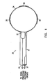
- Fig. 1 is a conceptual, schematic illustration of the distal end of a catheter 20.
- the catheter comprises an outer sheath or sleeve 22 and a substantially rigid ring 24 at the catheter's distal end.
- a plurality of sensor electrodes 26, 28, 30 are fixed to ring 24 in such manner that when the ring is placed against a biological tissue, such as the endocardium, the electrodes receive electrical signals from the tissue. These signals are conveyed by conducting wires 31 inside sheath 22 to signal processing electronics, not shown in the drawings.
- Electrodes 26, 28, 30, and signal processing electronics for electrophysiological measurements in the heart are known in the art and do not form a part of the present invention.
- ring 24 or another structure at the distal end of catheter 20 may comprise only two electrodes.
- the two electrodes may be successively repositioned about a location in the tissue so as to make multiple successive measurements, which are collectively used for determining the direction of a vector at the location.
- the three electrodes 26, 28 and 30, as shown in Fig. 1 are sufficient for determining the direction of a velocity vector in the biological tissue with which they are in contact, in accordance with preferred embodiments of the present invention.
- larger numbers of electrodes may be attached to ring 24.
- the additional data provided by the greater number of electrodes may be used to determine the vector with greater accuracy, or to resolve anomalous measurements due to pathologies in the tissue, for example.
- Catheter 20 further comprises a device 32 for generating six-dimensional position and orientation coordinate information.
- Coordinate information device 32 provides electrical signals via conducting wires 33 to signal processing electronics (not shown in the drawings), which determine the six coordinates of translational position and angular orientation of device 32 relative to an external frame of reference.
- signal processing electronics not shown in the drawings
- coordinate information device 32 is attached to ring 24 or is placed adjacent to the distal end of the catheter in a fixed, known relation to ring 24, so that the position and orientation of ring 24 are known relative to device 32.
- the coordinate information device may be located at any point along the length of the catheter, although it is preferably located near the distal end.
- substantially rigid as applied to ring 24 at the distal end of catheter 20, is taken to mean that during successive measurements of electrophysiological signals by the electrodes, the shape of the ring and its angular orientation relative to coordinate information device 32 remain substantially unchanged. Consequently, the location of each of the electrodes on the ring relative to coordinate information device 32 is substantially constant, and thus the locations of all the electrodes relative to an external reference frame may be determined using the location and orientation information provided by the coordinate information device. During insertion and removal of the catheter from the body, however, this relationship may not be preserved.
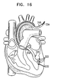
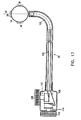
- Catheter 20 is used as part of a system for mapping physiological activity, as illustrated schematically in Fig. 2 .
- a surgeon 21 inserts catheter 20 through an incision into a chamber of heart 23 of a patient 25, so that ring 24 with its associated electrodes (not shown in Fig. 2 ) and coordinate information generating device 32 are inside the chamber.
- device 32 In accordance with an exemplary position determination device described in PCT patent application number PCT/US95/01103, filed January 24, 1995 , and U.S. patent 5,391,199 , which are assigned to the assignee of the present application, device 32 generates position signals in response to externally applied magnetic fields, generated by electromagnetic field generator coils 27, which are fixed to the operating table 29.
- Catheter 20 is connected at its proximal end via a cable 37, which contains conducting wires 31 and 33 (shown in Fig. 1 ), to signal processing electronic circuits 39.
- Field generator coils 27 are similarly connected via cable 41 to driver circuits 43.
- Circuits 39 and 43 are connected to a computer 51, which controls their operation and receives signals therefrom, and which is also coupled to monitor screen 53.
- surgeon 21 operates catheter 20 so as to bring ring 24 to bear against a point on the endocardium 55.
- Circuits 39 receive and process position signals generated by device 32 and electrical signals received by electrodes 26, 28 and 30 (shown in Fig. 1 ), and convey these signals to computer 51.
- the computer uses the processed signals to determine the locations of electrodes 26, 28 and 30 and to compute a local electrical activation vector 38, as will be described below with reference to Fig. 3 .
- the surgeon operates the catheter so as to move the ring to multiple other points on the endocardium, repeating the above steps at each such point.
- the computer uses the signals receive at the multiple points to generate a map of vector 38, which is displayed, along with other useful data, on monitor screen 53.
- the map may also be stored and recorded for later use, by means and methods known in the art.
- measurements by coordinate information device 32 are substantially synchronized with the heart cycle, with all measurements made during diastole, for example, so as to eliminate errors, that may arise in determining positions of electrodes 26, 28 and 30, due to movement of the heart.
- the electrodes however, remain fixed in their positions adjacent to the endocardium during all parts of the heart cycle, until the surgeon moves them.
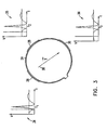
- Fig. 3 shows ring 24 and electrodes 26, 28, 30 thereon, together with representations of electrograph signals 34, 35, 36 that are typically received from electrodes 26, 28, 30, respectively, when the ring is positioned so that the electrodes are in contact with the endocardium.
- Signals 34, 35 and 36 are shown schematically for explanatory purposes only.
- vector V 38 represents the direction of an electrical activation vector in the endocardium at the location of the ring.
- the sharp electrical impulse peak shown in graphs 34, 35 and 36 will reach electrode 26 first, at time t 1 , and subsequently electrode 28, at time t 2 , and finally, electrode 30, at time t 3 .
- a sharp electrographic impulse peak which is seen in the well-known QRS portion of the electrocardiogram waveform, propagates through the heart muscle to induce contraction.
- the relative time of arrival of the signal peak at each of the electrodes can thus be used to determine the magnitude and direction of V relative to ring 24.
- This temporal measurement indicates that the electrical activation wave front passing electrode 26 takes twice as long to reach electrode 30 as it does to reach electrode 28, and thus that vector V points from the position of electrode 26 toward that of electrode 30. If the ratio ⁇ 2 / ⁇ 3 were relatively smaller, V would be found to be rotated clockwise relative to the direction shown in Fig. 3 , while if the ratio were larger, V would be rotated counterclockwise.
- the present invention may comprise four or more electrodes.
- the additional arrival time data provided by the larger number of electrodes may be used to determine the direction of V with greater accuracy.
- inventions of the present invention may include only two electrodes, in which case a single measurement will give a general indication of the direction of V , and multiple, sequential measurements may be used to determine the direction of V with greater accuracy. It is generally preferable, however, that the distal end of the catheter comprise at least three non-collinear electrodes, so that the vector V may be fully determined as shown in Fig. 3 .
- amplitudes of signals 34, 35 and 36 are all roughly the same, at certain locations in the endocardium, and particularly in the vicinity of pathological areas of the heart, the relative amplitudes of the signals may vary, and these amplitude variations may also be useful in locating and diagnosing the pathology.
- pairs of electrodes such as electrodes 26 and 28, may be coupled together so as to act as bipolar electrodes.
- the signal processing electronics will detect the electrical potential difference between electrodes 26 and 28, for example, corresponding substantially to the local electrical activity between the electrodes. If, in this example, the direction of the local electrical activation vector V has a large component directed from electrode 26 toward electrode 28, the bipolar signal measured between these electrodes will have relatively large amplitude. If the vector has a large component directed from electrode 28 toward electrode 26, the bipolar signal will also have relatively large amplitude, although of opposite sign to that of the preceding case. If, however, the vector points in a direction substantially perpendicular to an axis passing through electrodes 26 and 28, the amplitude of the bipolar signal will be relatively small or zero.
- any direction of the vector V can be decomposed into components parallel and perpendicular to an axis passing through a pair of electrodes, and the amplitude of the bipolar signal between these electrodes will be proportional to the relative magnitude of the parallel component.
- the direction of the local electrical activation vector V can be determined using the relative amplitudes rather than the arrival times of the signal peaks.
- the direction of vector V can be determined relative to the external frame of reference.
- This external Name of reference is preferably substantially fixed in relation to the heart muscle, using methods that will be discussed in greater detail below.
- FIG. 4A shows a structure 240 at the distal end of a catheter 220, which is similar to the structure of Figs 10A-10C .
- Structure 240 at the distal end of catheter 20 comprises a plurality of arms 242 to which electrodes 226, 228 and 230 are fixed in known relative positions.
- the electrodes are placed into contact with the endocardium of the heart of a subject, and generate local electrogram signals in response to electrical potentials in the endocardium.
- signals are preferably conveyed through arms 242 and catheter 220 to signal processing apparatus 248, which processes the signals to determine a local activation time at the respective position of each of the electrodes.
- catheter 220 is useful, it is shown in Fig. 4A only by way of illustration, for clarity in describing a method of velocity determination.
- the method as described below may similarly be used in conjunction with other types of structures that allow for placement of electrodes at known, spaced positions in contact with physiological tissue, such as those described herein.
- a Cartesian coordinate frame 244 is defined by the positions of the catheter and the electrodes, wherein the Z-axis is aligned with the long axis of catheter 220, the Y-axis is defined by a line normal to the Z-axis and passing through electrode 226, and the X-axis is perpendicular to both the Y- and the Z-axes.
- the positions of electrodes 226, 228 and 230 are marked respectively as A, B and C in the figure in coordinate system 244, for clarity in the explanation that follows.
- position- and orientation-responsive signals generated by device 232 are conveyed to position sensing apparatus 246, which uses the signals to compute position and orientation coordinates of the catheter relative to a reference frame 250, comprising K, L and M axes as shown in Fig. 4A , defined by external radiator coils 27, which generate the magnetic fields.
- the position of the origin and the orientation of frame 244 are calibrated in relation to frame 250, before beginning to measure and map the electrical activation time.
- the distal portion of catheter 220 is placed in a known location and oriented so that each of the X, Y and Z axes of coordinate frame 244 is substantially aligned with one of the K, L and M axis of coordinate frame 250.
- the position and orientation coordinates of catheter 220 at this location and orientation, as computed by position sensing apparatus 246, are then recorded and used subsequently as zero-reference points in computing position and orientation coordinates of the catheter during measurement and mapping.
- at least one of the electrodes is selected as the reference electrode and is aligned with one of axes K, L or M.
- a local reference frame such as one coupled to the heart may be used, as described herein.
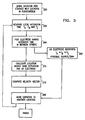
- Figs. 4B-D and 5 illustrate a method for mapping a vector velocity of electrical activation V , as a function of time, in the endocardium, using catheter 20 or similar apparatus.
- Fig. 5 is a flowchart of the method, while Figs. 4B-D illustrate the method on a schematic of electrodes 226, 228 and 230.
- the catheter is brought into contact with a location in the endocardium, and positions A, B and C are determined, corresponding to the respective positions of electrodes 226, 228 and 230 and to respective portions of the endocardium. It will be appreciated that iit is sufficient to determine the position and orientation of distal end of catheter 20, in order to determine A, B and C.
- Measurement of electrical activation time is performed according to methods known in the art, for example by sensing sharp peaks in the electrogram signals received from the electrodes and determining thereby the relative time at which the local tissue depolarizes, as described above in reference to Fig. 3 .
- the depolarization time can be determined using bipolar electrodes, for example, by coupling together pairs of electrodes, such as electrodes 226 and 228, so as to act as bipolar electrodes.
- the signal processing electronics will detect the electrical potential difference between electrodes 226 and 228, for example, corresponding substantially to the local electrical activity between the electrodes. If, in this example, the direction of the local velocity vector V has a large component directed from electrode 26 toward electrode 28, the bipolar signal measured between these electrodes will have relatively large amplitude.
- each of electrodes 226, 228 and 230 is a bipolar electrode comprised of two individual electrodes).
- the local electrical activation times are compared so as to identify one of electrodes 226, 228 and 230 whose local electrical activation time is not equal to those of the other two electrodes. If such an electrode cannot be found, i.e., the local activation times of all three electrodes are equal or cannot be measured, then the local activation velocity V is determined to be zero, and the location in the endocardium with which the catheter is in contact is identified as a suspected site of pathology, for example a source or sink of electrical activation.
- Catheter 220 may be moved to a new location on the endocardium, which location is a short distance from the previous location, such that there is substantial overlap in the endocardium which is mapped in the new location and in the previous location. Thus, it is possible to identify whether the previous location is a source, a sink, or possibly, dead scar tissue. It should be appreciated, that such precise relocalization is made possible using position sensing device 232.
- a velocity map is repeated after a medical procedure, such as surgery or an ablation (even of a single point) and/or after a different pacing scheme is sued.
- a medical procedure such as surgery or an ablation (even of a single point) and/or after a different pacing scheme is sued.
- Such temporally repeated mappings can be used to asses the advance of arrhythmias, as one effect of abnormal conduction is that the conduction velocity changes with time.
- the vector of the depolarization potential changes during the cardiac cycle. Measuring this vector, even at a single location in the heart, can provide much information regarding the functioning of the heart. If four non-coplanar electrodes are provided for in the catheter, the three-dimensional potential vector of the heart may be determined.
- the electrode found to have the latest activation time, ⁇ max is marked “c”
- the electrode with the earliest activation time, ⁇ min is marked “d”
- the electrode with the intermediate activation time, ⁇ between is marked "b”.
- a point “a” indicates a (calculated) location on the line connecting "c” and “d” which has the same activation time as electrode "b".
- the local isochronals are all assumed to be parallel to line “ab", which connects point "a” and point "b”.
- the validity of this assumption increases, as does the precision of the method.
- the local isochronals are assumed to be all parallel to the line connecting the two electrodes, and the velocity vector is perpendicular to the connecting line.
- V is now computed, based on the following procedure, illustrated by Fig. 4C .
- Point “p” is located on the line “ab” connecting points "a” and "b", such that velocity vector V is perpendicular thereto.
- A, B and C are vector coordinates of the electrodes (in reference frame 244 or 250) and are referred to as A , B and C .
- a method for mapping a vector velocity of electrical activation V , as a function of time, in the endocardium uses catheter 20 or similar apparatus: First, the catheter is brought into contact with a location in the endocardium, and vectors A , B and C , are determined, corresponding to the respective positions of electrodes 226, 228 and 230. It will be appreciated that, with reference to Fig. 4A , it is sufficient to determine the position and orientation of distal end of catheter 220, in order to determine A , B and C .
- Measurement of electrical activation time is performed according to methods known in the art, for example by sensing sharp peaks in the electrogram signals received from the electrodes and determining thereby the relative time at which the local tissue depolarizes, as described above in reference to Fig. 3 .
- the local electrical activation times are compared so as to identify one of electrodes 226, 228 and 230 whose local electrical activation time is not equal to those of the other two electrodes. If such an electrode cannot be found, i.e., the local activation times of all three electrodes are equal or cannot be measured, then the local activation velocity V is determined to be zero, and the location in the endocardium with which the catheter is in contact is identified as a suspected site of pathology, for example a source or sink of electrical activation.
- electrode 226 is found to have a local electrical activation time different from those of electrodes 228 and 230, and is thus taken as a reference point for determination of V . It will be appreciated, however, that the method described below will be equally applicable if either electrode 228 or electrode 230 is thus found and taken as the reference.
- V is now computed, based on the following procedure.
- Velocity component vectors P B and P C are determined based on the measured electrode positions and local electrical activation times:
- P ⁇ B B ⁇ - A ⁇ ⁇ B - ⁇ A
- P ⁇ C C ⁇ - A ⁇ ⁇ C - ⁇ A
- P ⁇ CB P ⁇ B - P ⁇ C
- P ⁇ CB P ⁇ CB P ⁇ CB
- V ⁇ P ⁇ B - P ⁇ CB ⁇ P ⁇ B ⁇ P ⁇ CB
- Another advantage of using this second, vector based, method is its simplicity. Another advantage is that the electrode plane need not be perpendicular to the catheter. A further advantage is that the velocity is unambiguously determined. It should be noted that the determined velocity vector is in the coordinates of the heart, not of the catheter, since the transformation between the internal and external frames cancels out when the calculations of equations (8)-( 12).
- Catheter 20 is then moved to another location, and the procedure described above is repeated multiple times, so as to generate a map of V as a function of location in the endocardium.
- this map is used to determine locations of defects in the propagation of electrical activation in the endocardium, particularly to find sources and sinks of the activation.
- the map may further be compared with maps generated at earlier times, so as to identify changes in the local activation velocity over time.
- ring 24 is made of resilient material.
- the ring is collapsed into an elongated shape so as to pass easily through the blood vessels.
- the ring is contained inside catheter sheath 22.
- the ring is coupled to a stiff pushing member 40, which extends the entire length of the catheter.
- Position information device 32 is also coupled to pushing member 40, proximal to ring 24.
- Position information device 32 simultaneously assumes its desired position adjacent to the distal end of catheter 20 inside sheath 22.
- coordinate information device 32 may be fixed in a constant position inside sheath 22, unaffected by the movement of pushing member 40.
- ring 24 is formed from a resilient, super-elastic material, such as NiTi.
- a resilient, super-elastic material such as NiTi.
- Such materials have the property that when a piece of the material is heated above a certain critical temperature, it may be bent or formed into a desired shape. If the material held in this shape while it is cooled to below the critical temperature, then it will subsequently resiliently retain the given shape. Thus, although it may be compressed or bent by exertion of sufficient force, once the force is removed, the super-elastic material will return resiliently to its given shape, in this case a ring.
- ring 24 is formed from a flat strip of material, which is bent into a ring shape. Once the ring has been ejected from the catheter, its elasticity causes it to bear against the edges of slot 42, so as to hold the ring in a known angular orientation relative to the axis 45 of the catheter and prevent rotation in a direction, indicated by ⁇ , about axis 45, as shown in Fig. 7 .
- the flat shape of the ring material effectively prevents the ring from tilting in an up-down direction, indicated by ⁇ , relative to axis 45.
- the flat surface of the ring also bears against the flat surface 43 of the distal end of the catheter, thereby preventing wobble of the ring in a side-to-side direction, indicated by ⁇ , relative to axis 45.
- electrodes 26, 28 and 30 extend to and, more preferably, extend below or around the lower edge of ring 24.
- electrodes 26, 28, 30 are attached to a ring 44 formed from a hollow section of substantially rigid material, such as a tube, which is closed off at its distal end.
- the ring is rigidly coupled to the distal end of catheter 20, so that its geometric shape and angular orientation relative to the axis of the catheter are known.
- Ring 44 also comprises coordinate information device 32 adjacent to its distal end. Alternatively, device 32 may be located in catheter 20.
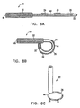
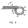
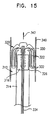
- a stylette 46 is inserted from the proximal end of the catheter, through catheter sheath 22 and into the lumen of the tube from which ring 44 is formed, thereby straightening the ring as shown in Fig. 8A .
- Only the distal end of stylette 46 is substantially rigid, and the remaining length of the wire may be flexible, as long as it is stiff enough to allow it to be pushed into the hollow center of ring 44 for insertion and removal of the catheter from the heart.
- ring 44 is so formed that when stylette 46 is withdrawn, the ring twists sideways, so that the axis of the ring is substantially parallel to the long axis of catheter 20. In this twisted orientation of ring 44, electrodes 26 (not shown), 28 and 30 attached to the ring may more easily be brought into contact with the endocardium.
- Ring 44 at the distal end of the catheter may be formed of a hollow section of flexible material.
- this hollow section is straightened by insertion of a straight stylette 46 into the lumen of the hollow section.
- a second stylette (not shown in the figures), formed of substantially rigid material and including a curved portion at its distal end, is inserted.
- the curved distal portion of the stylette is straightened, and the relative stiffness of the catheter causes the stylette to remain straight as it is passed through the catheter.
- distal tip 47 of the ring section engages a socket 49 in the side of the catheter.
- Fluoroscopy or other methods of imaging known in the art may be used to observe ring 44 at the distal end of the catheter and verify that distal tip 47 of the distal section has engaged socket 49, so as to ensure that the ring has assumed its desired shape and orientation prior to beginning electrophysiological measurements.
- distal tip 47 of the distal section of the catheter comprises a first electrical contact, not shown in the figures, and socket 49 in the side of the catheter comprises a second electrical contact, likewise not shown.
- first electrical contact is brought into proximity with the second electrical contact.
- the mutual proximity of the contacts is measured electrically using methods known in the art, so as to verify that the distal tip has engaged the socket.
- the devices may comprise structures having other geometrical shapes and/or other cross-sectional profiles for placement of electrodes.
- the cross-sectional profile of the structure may be non-uniform.
- the electrodes are shown in the figures as being attached externally to rings having smooth outer surfaces, in other preferred embodiments of the present invention, the rings may include recesses into which electrodes or other sensors are inserted.
- the electrodes are placed on a structure comprising rigid and flexible, resilient sections.
- the flexible sections bend, causing the structure on which the electrodes are placed to collapse into a narrow shape.
- the resilience of these sections causes the structure to open out for making measurements once inside the heart.
- any desired geometrical structure may be used for electrode placement, as long as the catheter and the devices for generating coordinate information are configured to allow determination of locations of all the electrodes.
- the catheter and the devices for generating coordinate information are configured to allow determination of locations of all the electrodes.
- one such device is placed adjacent to each of the electrodes, so that it is not necessary to explicitly determine the angular orientation of the structure holding the electrodes.
- the structure in which the electrodes are placed at the distal end of the catheter is polygonal, most preferably triangular.
- the vertices of the polygonal structure When the vertices of the polygonal structure are brought into contact with the endocardium, they will typically lodge in small crevices in the heart tissue, thus preventing the structure from moving during measurement, despite the natural motion of the heart.
- the electrodes are attached at or near the vertices.
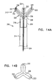
- structure 60 at the distal end of the catheter comprises multiple arms 62, 64 and 66. Electrodes 26, 28 and 30 are attached to the respective arms.
- arm 62 comprises two substantially rigid sections 68 and 70, which are joined by resilient joint 72. This joint is formed in such a manner that it causes sections 68 and 70 to maintain a mutual alignment that is substantially collinear, as shown in Fig. 10B , when no external forces are exerted thereon. (Although for the sake of simplicity, sections 68 and 70 and joint 72 are marked in Fig.
- arms 64 and 66 are similarly constructed.
- the arms are joined at their proximal ends to the distal end of catheter 20.
- the distal ends of the arms are joined together at flexible joint 74.
- Draw-wire 76 is also connected at its distal end to joint 74, and passes through a lumen of catheter 20 to its proximal end (not shown).
- draw-wire 76 is released, and the resilience of joints 72 causes sections 68 and 70 to maintain a substantially collinear mutual alignment, parallel to the long central axis 45 of the catheter.
- draw-wire 76 is pulled back toward the proximal end of catheter 20, exerting a proximally-directed force on flexible joint 74, and thereby causing resilient joints 72 to flex, as shown in Fig. 10A .
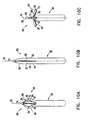
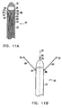
- electrodes 26, 28 and 30 are fixed adjacent to and aligned with the distal ends of substantially rigid arms 80, 82 and 84 respectively.
- the arms are contained inside respective lumens 85, 86 and 87 of the catheter, wherein the distal ends of the arms are adjacent to small radial openings 88, 90 and 92, respectively, in sheath 22 of the catheter.
- a device 32 for generating coordinate information is adjacent to the distal end of the catheter.
- arms 80, 82 and 84 are pushed out through their respective radial openings, as shown in Fig. 11B .
- the resilience of the arms causes electrodes 26, 28 and 30 to assume predetermined positions, distal to the catheter's distal end and mutually-spaced about its long central axis 45.
- the distal end of the catheter may chafe or scrape an inner surface of the vessel, not only making the insertion of the catheter difficult, but possibly causing damage to the vessel.
- Another possibility of damage occurs after the distal end of the catheter has entered an organ such as a chamber of a heart. Since the distal end is usually thin, care must be exercised to prevent accidentally puncturing, scraping or otherwise damaging inner walls of the organ.
- Another problem relates to the possibility of formation of blood clots in cracks or sharp corners which are formed at the tip of the catheter.
- the structure to which electrodes are fixed at the distal end of the catheter may be coupled to an inflatable element, such as a balloon. After the catheter has been inserted into the heart, the inflatable element is inflated and causes the structure to assume a predetermined, known shape and orientation relative to the distal end of the catheter.
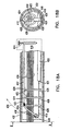
- a catheter 20 comprises a balloon 93 at the catheter's distal end, wherein electrodes 26, 28 and 30 are attached to the surface of the balloon.
- the electrodes may be mechanically fastened to the balloon, or they may be chemically deposited on the balloon's surface using methods of electroplating or coating known in the art.
- Balloon 93 contains and protects a wire basket structure 94, which typically includes lateral wires 95 and axial wires 96 connected to electrodes 26, 28 and 30.
- Wires 95 and 96 are flexible, so that they may bend freely, but they are non-extensible, i.e., their length remains substantially constant when a tensile, stretching force is applied to them.
- Axial wires 96 are connected at their proximal ends to an anchor 97, which is in turn connected to a device 32 for generating coordinate information.
- balloon 93 is deflated, thereby causing wires 95 and 96 to bend, so that basket structure 94 collapses into a narrow elongated shape.
- balloon 93 is inflated by methods known in the art, such as by introducing a fluid into the interior thereof through a lumen of the catheter (not shown in the figure). Inflation of balloon 93 causes basket structure 94 to expand and become substantially rigid.
- wires 95 and 96 are pulled taut, so that electrodes 26, 28 and 30 assume known positions, relative to one another and relative to anchor 97, as determined by the lengths of wires 95 and 96. Because the wires are non-extensible, additional inflation of balloon 93 beyond the size necessary to straighten the wires will not affect the relative positions of the electrodes.
- balloon 93 is again deflated.
- catheter 20 comprises at its distal end a balloon 93 and a collapsible structure 98.
- Structure 98 includes a substantially rigid axial member 99, which is contained inside balloon 93, and a plurality of radial members 101 coupled to the balloon on its outer surface.
- Radial members 101 comprise joints 103, so that when the balloon is deflated, as shown in Fig. 13A , the radial members fold down, and structure 98 assumes an elongated, narrow shape for ease of insertion into the body.
- Electrodes 26, 28 and 30 are fixed to the distal ends of radial members 101.
- Axial member 99 is attached at its proximal end to anchor 97, which is in turn connected to a device 32 for generating coordinate information.
- Structure 98 further comprises flexible, non-extensible wires 105, each of which is respectively attached at its proximal end to a point on axial member 99 or anchor 97, and at its distal end to a point adjacent to the distal end of a respective radial member 101.
- balloon 93 is inflated, thereby causing joints 103 to straighten, so that radial members extend radially outward from a central axis defined by axial member 99.
- wires 105 are pulled taut, thereby constraining joints 103 from bending any further than desired.
- Structure 98 thus becomes substantially rigid, so that electrodes 26, 28 and 30 assume known positions, relative to one another and relative to anchor 97, as determined by the structure. Because the wires are non-extensible, additional inflation of balloon 93 beyond the size necessary to straighten the wires will not affect the relative positions of the electrodes.
- the electrodes deposited on the balloon may be of any desirable configuration, including, three unipolar electrodes, three bipolar electrodes, a line of electrodes.
- the balloon/structure may be adapted for a particular body structure, such as near the mitral valve, by suitable design of the inflated form of the balloon/structure.
- FIG. 14A illustrates a catheter 310 and a covering 312 attached thereto, constructed and operative in accordance with a preferred embodiment of the present invention.
- Catheter 310 may any known type of catheter suitable for insertion into a body vessel, and preferably includes a tubular body portion 314 having a distal end 316.
- Covering 312 preferably includes a resilient cap member 320 extending distally from distal end 316.
- Resilient cap member 320 preferably includes a tuft of distally extending, resilient lobes 322 with soft, smooth outer surfaces.
- Resilient cap member 320 is preferably constructed of an elastomeric material, such as rubber or latex.
- Lobes 322 are preferably substantially symmetrically arranged about a longitudinal axis 324 of catheter 310.
- Fig. 14A illustrates three lobes 322 substantially mutually spaced 120° apart about axis 324. It is appreciated that covering 312 may alternatively comprise any other number of lobes 322, including only a single off-axis lobe.
- a sleeve 326 extends from a proximal end 328 of resilient cap member 320 and snugly fits over distal end 316 of the catheter.
- At least one radial dimple 330 is preferably formed at a juncture between sleeve 326 and the resilient cap member 320.
- the radial dimple makes it easier for the lobes to bend backwards, by providing a volume to accommodate a portion of the lobe and enable a sharper bend angle with less stress on the cap.
- the dimple strengthens the connection between covering 312 and catheter 310.
- At least one sensor 332 is fixed to resilient cap member 320. As seen in Fig. 14A , most preferably one or more sensors 332 are embedded inside each lobe 322. Sensors 332 may be any type of sensor useful in sensing a physiological activity. Sensor 332 may include a monopolar electrode or a bipolar electrode, useful for determining local electrical activity, such as local activation time. Additionally, sensor 332 may include a strain gauge useful for determining muscle contraction. Sensors 332 may be in wired communication with sensor processing equipment (not shown) by means of wires 334 which are preferably embedded in lobes 322 along with sensors 332. Alternatively, sensors 332 may be capable of wireless transmission to sensor processing equipment (not shown).
- a position sensor (not shown) is embedded in lobe 322, preferably near sensor 332, so as to more exactly determine the relative position of sensor 332.
- One aspect of electrophysiological mapping is assuring that sensors 332 do not slip along the myocardium during the cardiac cycle.
- there may be provided at least one bump 336 which protrudes from lobe 322 of resilient cap member 20. All or a portion of lobes 322 may be provided with one or more bumps 336.
- Bump 336 is preferably integrally formed with lobe 322.
- the bump 336 may include therein one or more of the sensors 332. It is appreciated that lobe 322 may have one sensor 332 inside bump 336 and another sensor 332 outside of bump 336. Bumps 336 may also serve to enhance the tissue contact and sensing capability of sensors 332.
- a path from the sensor should be provided to the contact point on the surface of the myocardium.
- This path which may be a conducting path to the end of a bump, depends on the nature of the measurement being performed.
- Fig. 14B shows a front view of catheter 310.
- at least one opening 333 to a lumen is formed in each lobe 322.
- a lumen may be used to provide an extendible barb for attaching the lobe to the myocardium.
- a lumen may be connected to a vacuum pump to provide anchoring via suction.
- such a lumen may be used to provide irrigation to the region of sensor 332.
- anchoring means such as barbs and suction are applied only after sensor 332 is in good contact with the myocardium. The quality of contact is preferably determined using electrical activity signals and/or impedance signals from sensors 332.
- cap 320 includes sensors 335 which generate indications of the relative positions of lobes 322.
- Each of lobes 322 has an embedded sensor 335.
- Local contraction time may be determined based on the signal generated by sensor 335. It should be appreciated that binary information (constant strain/change in strain) is enough to determine the onset of such movement. However, preferably, the resolution of the signal from sensor 335 is sufficient to determine the relative positions of lobe 322 and cap 320.
- a strain gauge can be used in any of the multi electrode embodiments described herein.
- Fig. 15 illustrates inserting catheter 310 into a body vessel 340 in a distal direction, indicated by an arrow 342.
- Resilient cap member 320 and/or its lobes 322 are resiliently inverted over distal end 316 of catheter 310 during the distally directed motion of catheter 310 in vessel 340.
- Lobes 322 may be resiliently inverted prior to insertion of catheter 310 into vessel 340.
- lobes 322 are inverted when the lobes hit an obstruction in vessel 340. If the obstruction is small, catheter 310 will glide by it.
- resilient inversion of resilient cap member 320 greatly facilitates insertion of catheter 310 into vessel 340, and provides a high degree of insertion safety, thereby substantially eliminating the possibility of catheter 310 scraping an inner surface of vessel 340. Because of radial dimple 330, there is substantially no build-up or bunching of material in the inverted state of lobes 322.
- cap member 320 Upon proximally directed motion of catheter 310 in vessel 340, resilient cap member 320 once again becomes non-inverted and generally reverts to the shape illustrated in Fig. 14A . Alternatively, in some embodiment of the invention, cap 320 reverts to its previous shape ( Fig. 14A ) when it is unconstrained by vessel 340, for example, when entering the heart.
- lobes 322 form a streamlined shape which does not interfere with the extraction.
- Fig. 16 illustrates using catheter 310 to sense a physiological activity of tissue inside a body organ, in accordance with a preferred embodiment of the present invention.
- the body organ shown is a heart, but it is appreciated that the invention may be carried out for any other body organ as well.
- the mapped organ is the brain, more flexible lobes are preferably used, as brain tissue is much weaker than vascular tissue and more liable to tear.
- Catheter 310 is inserted into a body organ, such as a left ventricle of a heart, typically via the aortic valve. Catheter 310 is inserted so that sensors 332 contact a tissue, such as the endocardium. Depending on the type of sensor, it may be sufficient to bring sensor 332 in close proximity to the tissue without having to actually touch the tissue. Resilient cap member 320 substantially prevents accidentally puncturing, scraping or otherwise damaging inner walls of the left ventricle, by virtue of its large cross-section. Sensors 332 then sense a physiological activity of the tissue. Sensors 332 may sense the physiological activity substantially simultaneously, or alternatively, one at a time.
- Sensors 332 may sense, for example, a movement of the tissue, contraction time of the myocardium, or an activation signal of the myocardium. In this way, the contraction time of the heart muscle relative to the activation signal of the heart muscle, may be determined. As a further example, sensors 332 may sense velocity of fluid flow in or near the tissue. In a preferred embodiment of the invention catheter 310 comprises at least four non-coplanar pressure sensors, so that a true three-dimensional pressure gradient may be calculated. Such a pressure may be easily converted into a velocity vector, as known in the art.
- the device that generates coordinate information 32 generates six-dimensional position and orientation information.
- device 32 may, for example, comprise a plurality of coils, and as described in PCT patent application number PCT/US95/01103, filed January 24, 1995 , which is assigned to the assignee of the present application.
- Preferred embodiments of this device use a plurality of non-concentric coils, (not shown in the figures), adjacent to a locatable site in catheter 20, for example near its distal end, or on the structure on which electrodes 26, 28, 30 are placed, such as ring 24 or 44.
- Device 32 generates coordinate information relative to an external reference frame defined by electromagnetic field generator coils 27, which are fixed to the external reference frame.
- inventions of the present invention comprise one or more devices for generating three-dimensional location information, as described, for example, in U.S. patent 5,391,199 , to Ben-Haim, and PCT patent application PCT/US94/08352 , which are assigned to the assignee of the present application.
- Devices for generating location information are placed in the structure containing the electrodes, in proximity to electrodes 26, 28, 30. The respective location information generated by these devices is used to determine the positions of the electrodes.
- two or more devices for generating three-dimensional location information are placed in known, mutually-spaced locations in the structure containing the electrodes, thereby allowing the positions of the electrodes in the structure to be determined.
- the device disclosed in the aforementioned '539 patent application for generating three-dimensional location information preferably comprises a single coil in catheter 20.
- the coil is toroidal in shape and coaxial with the long, central axis of the catheter.
- a device that generates three-dimensional location information is placed in the catheter adjacent to the electrodes and is used to determine the location of the catheter inside the heart, while one or more rotation measuring devices measure the angular orientation of the catheter.
- the rotation measuring devices may be of any suitable type known in the art, such as, for example, shaft encoder devices adjacent to the proximal end of the catheter.
- a catheter 20 comprises at its distal end a substantially rigid ring 24 to which electrodes 26, 28 and 30 are fixed.
- the catheter further comprises a device that generates three-dimensional location information 100, which device preferably comprises a coil coaxial with the long central axis 45 of catheter 20.
- a tip deflection device 102 causes the distal end of the catheter to flex from side to side within a plane defined by ring 24, under the control of steering wire 104. This device is not in accordance with the invention.
- Handle 106 includes a first control knob 108, which is coupled to steering wire 104 via a drum and thereby controls the flexing of tip deflection device 102, and a second control knob 110, which controls the rotation of the catheter about its long central axis 45.
- Shaft encoders 112 and 114 are coupled to knobs 108 and 110 respectively, and generate information regarding the tip deflection and rotation angles of the catheter.
- the location information generated by device 100 taken together with the angles of rotation and deflection of the catheter as determined from the information generated by shaft encoders 112 and 114, is sufficient to track the location and orientation of ring 24 in the heart relative to a known starting position. If desired, the starting position may be verified by fluoroscopy or another imaging technique known in the art.
- Figs. 18A and 18B illustrate a catheter steering mechanism for a catheter 432.
- the mechanism indicated by the dotted line, includes a stiffener 420 attached to a flat, flexible, elastic, member 416.
- the distal portion of member 416 is coiled into a spiral, through which a loop 430 is threaded.
- Loop 430 is formed at a distal end of a pull wire 412, which when pulled, cause flexible member 416 to bend, thereby bending the tip of catheter 432. Since member 416 is flat, it has a preferred bending plane perpendicular to its face, along arrow 434.
- pull wire 412 is preferably wound on a shaft 414, such that when shaft 414 is rotated, pull wire 412 is either tensed or relaxed, based on the turn direction.
- Pull wire 412 is preferably formed of Kevlar.
- loop 430 surrounds inner wires 428 of catheter 423.
- Wires 428 usually transmit sensor signals to and from the sensors and/or electrodes and or position sensors at the distal end of a catheter 432.
- a plurality of spaces 422 separate member 416 from pull wire 412, so that they do not get tangled together.
- spacers 422 may be flexible (but inelastic) and are also preferably formed of Kevlar.
- field generator coils 27 fixed to operating table 29 define an external reference frame, relative to which the position of position information generating device 32 is determined.
- an external reference frame is defined and fixed relative to the heart muscle, as described, for example, by U.S. patent 5,391,199 and U.S. provisional patent application 60/009,769, filed January 11, 1996 , which are assigned to the assignee of the present application.
- These disclosures teach apparatus and methods for mapping the interior of the heart using two catheters, each of which includes a device that generates coordinate information.
- One of the catheters is positioned in a predetermined, substantially fixed location in the heart, preferably at the apex of the heart, and serves as a reference catheter.
- the first catheter 20 comprises ring 24 with electrodes 26, 28, 30 and coordinate information generating device 32 at its distal end, as described above.
- a second catheter also comprises a coordinate information generating device adjacent to its distal end, and is positioned in a predetermined, substantially fixed location in a chamber of the heart, preferably at the apex of the heart. This second catheter thus defines a reference frame that is substantially fixed with respect to the heart, relative to-which the position of the first catheter is determined.
- This method has the advantage that errors in mapping the propagation of electrical impulses in the heart that may arise due to motion of the heart and chest are avoided, and furthermore that electrical propagation vectors, such as activation vector V , may be mapped relative to an accurate map of the interior of the heart generated in accordance with U.S. patent 5,391,199 and U.S. provisional patent application 60/009,769, filed January 11, 1996 .
- the frame of reference defined by the second catheter also enables the operator to navigate the first catheter around the interior of the heart without the need for simultaneous fluoroscopic or other imaging.
- ultrasound or X-ray imaging may be used to determine the position of the first and/or second catheter in relation to the heart, so as to verify the reference points of the mapping of propagation of electrical impulses in the heart.
- the catheter to be imaged must include a suitable radio-opaque or ultrasound-reflecting marker.
- the field generator coils that provide the reference frame for coordinate information device 32 may be fixed externally to the patient's body. Position detection is synchronized with an external electrocardiogram signal, so that the position is always detected at the same point in the heartbeat, and the influence of the heart's motion on the detected position of the catheter is neutralized.
- Movements of the patient's thorax due to respiration may also be detected, using methods known in the art, such as bio-impedance measurement.
- Position detection is synchronized with the respiration cycle, for example by accepting signals from coordinate information device 32 only at and immediately following maximum exhalation or only during the tail end of exhalation, so as to eliminate errors in position measurement that may generally arise as the result of such movements.
- sensors such as ionic sensors, may be used instead of the electrodes to perform localized measurements and map other aspects of physiological activity.
- the distal end of the catheter may be placed in proximity to the suspected site of a defect.
- the catheter is then moved toward the suspected defect site. This procedure is repeated until the catheter reaches the actual site of the defect.
- the defect is located by the above procedure, it is ablated or otherwise treated by methods known in the art. It should be appreciated, that this procedure may be performed even without reference to a reference frame outside of the catheter.
- Arrhythmias and pathological cardiac events may also be detected, using methods known in the art, simultaneously with determining the velocity vectors in accordance with the method described above.
- Each velocity vector is classified and stored, preferably by computer 51 or other electronic data storage device, according to a type of cardiac arrhythmia or event (or normal heart beat) that occurred at the time the electrogram signals used to determine the vector were received.
- Stored vectors that have been classified as belonging to a specific arrhythmia or event are then used to generate a map of the propagation of electrical activation in the heart that is characteristic of that arrhythmia or event.
- Such maps may be useful, for example, in detecting abnormal propagation of the activation front that is associated with a specific arrhythmia, including cases in which multiple activation fronts pass a location in the heart during a single R-R cardiac cycle interval.
Landscapes
- Health & Medical Sciences (AREA)
- Life Sciences & Earth Sciences (AREA)
- Engineering & Computer Science (AREA)
- Animal Behavior & Ethology (AREA)
- Veterinary Medicine (AREA)
- Public Health (AREA)
- Biomedical Technology (AREA)
- General Health & Medical Sciences (AREA)
- Surgery (AREA)
- Heart & Thoracic Surgery (AREA)
- Molecular Biology (AREA)
- Medical Informatics (AREA)
- Physics & Mathematics (AREA)
- Pathology (AREA)
- Biophysics (AREA)
- Nuclear Medicine, Radiotherapy & Molecular Imaging (AREA)
- Cardiology (AREA)
- Radiology & Medical Imaging (AREA)
- Hematology (AREA)
- Physiology (AREA)
- Optics & Photonics (AREA)
- Vascular Medicine (AREA)
- Mechanical Engineering (AREA)
- Human Computer Interaction (AREA)
- Electromagnetism (AREA)
- Hospice & Palliative Care (AREA)
- Otolaryngology (AREA)
- Orthopedic Medicine & Surgery (AREA)
- Robotics (AREA)
- Measurement And Recording Of Electrical Phenomena And Electrical Characteristics Of The Living Body (AREA)
- Media Introduction/Drainage Providing Device (AREA)
- Measuring Pulse, Heart Rate, Blood Pressure Or Blood Flow (AREA)
- Prostheses (AREA)
- Materials For Medical Uses (AREA)
- Laser Surgery Devices (AREA)
- Electrotherapy Devices (AREA)
Applications Claiming Priority (9)
| Application Number | Priority Date | Filing Date | Title |
|---|---|---|---|
| IL11669996 | 1996-01-08 | ||
| IL11669996A IL116699A (en) | 1996-01-08 | 1996-01-08 | Method of building a heart map |
| US976996P | 1996-01-11 | 1996-01-11 | |
| US9769P | 1996-01-11 | ||
| US08/595,365 US5738096A (en) | 1993-07-20 | 1996-02-01 | Cardiac electromechanics |
| US1172196P | 1996-02-15 | 1996-02-15 | |
| US11721P | 1996-02-15 | ||
| EP97900037A EP0888082B1 (en) | 1996-01-08 | 1997-01-08 | Mapping catheter |
| US595365 | 2000-10-05 |
Related Parent Applications (1)
| Application Number | Title | Priority Date | Filing Date |
|---|---|---|---|
| EP97900037A Division EP0888082B1 (en) | 1996-01-08 | 1997-01-08 | Mapping catheter |
Publications (3)
| Publication Number | Publication Date |
|---|---|
| EP1382293A2 EP1382293A2 (en) | 2004-01-21 |
| EP1382293A3 EP1382293A3 (en) | 2004-01-28 |
| EP1382293B1 true EP1382293B1 (en) | 2008-07-02 |
Family
ID=27452467
Family Applications (3)
| Application Number | Title | Priority Date | Filing Date |
|---|---|---|---|
| EP03077584A Expired - Lifetime EP1382293B1 (en) | 1996-01-08 | 1997-01-08 | Mapping catheter |
| EP04075665A Withdrawn EP1428472A3 (en) | 1996-01-08 | 1997-01-08 | Mapping catheter |
| EP97900037A Expired - Lifetime EP0888082B1 (en) | 1996-01-08 | 1997-01-08 | Mapping catheter |
Family Applications After (2)
| Application Number | Title | Priority Date | Filing Date |
|---|---|---|---|
| EP04075665A Withdrawn EP1428472A3 (en) | 1996-01-08 | 1997-01-08 | Mapping catheter |
| EP97900037A Expired - Lifetime EP0888082B1 (en) | 1996-01-08 | 1997-01-08 | Mapping catheter |
Country Status (9)
| Country | Link |
|---|---|
| US (2) | US6600948B2 (enExample) |
| EP (3) | EP1382293B1 (enExample) |
| JP (1) | JP4027976B2 (enExample) |
| AU (1) | AU715925B2 (enExample) |
| CA (1) | CA2242353C (enExample) |
| DE (1) | DE69738547T2 (enExample) |
| ES (2) | ES2307871T3 (enExample) |
| IL (2) | IL116699A (enExample) |
| WO (1) | WO1997024983A2 (enExample) |
Families Citing this family (326)
| Publication number | Priority date | Publication date | Assignee | Title |
|---|---|---|---|---|
| US6136019A (en) * | 1996-08-19 | 2000-10-24 | Mower Family Chf Treatment Irrevocable Trust | Augmentation of electrical conduction and contractility by biphasic cardiac pacing administered via the cardiac blood pool |
| WO1998030144A1 (en) | 1997-01-08 | 1998-07-16 | Biosense Inc. | Monitoring of myocardial revascularization |
| JP4175662B2 (ja) | 1996-01-08 | 2008-11-05 | インパルス ダイナミクス エヌ.ヴイ. | 電気的筋肉制御装置 |
| US9289618B1 (en) | 1996-01-08 | 2016-03-22 | Impulse Dynamics Nv | Electrical muscle controller |
| US9713723B2 (en) | 1996-01-11 | 2017-07-25 | Impulse Dynamics Nv | Signal delivery through the right ventricular septum |
| WO1997044089A1 (en) * | 1996-05-17 | 1997-11-27 | Biosense Inc. | Self-aligning catheter |
| US6786896B1 (en) * | 1997-09-19 | 2004-09-07 | Massachusetts Institute Of Technology | Robotic apparatus |
| ATE289182T1 (de) | 1997-01-03 | 2005-03-15 | Biosense Webster Inc | Krümmungsempfindlicher katheter |
| US6272371B1 (en) | 1997-01-03 | 2001-08-07 | Biosense Inc. | Bend-responsive catheter |
| DE99911188T1 (de) * | 1998-03-05 | 2005-06-23 | Boston Scientific Ltd., St. Michael | Expandierbare vorrichtung zur transmyokardialen revaskularisation und verfahren |
| SE9801006D0 (sv) * | 1998-03-25 | 1998-03-25 | Siemens Elema Ab | Method and arrangement for determining the location of a catheter within an animal body |
| US6447504B1 (en) | 1998-07-02 | 2002-09-10 | Biosense, Inc. | System for treatment of heart tissue using viability map |
| US6226542B1 (en) | 1998-07-24 | 2001-05-01 | Biosense, Inc. | Three-dimensional reconstruction of intrabody organs |
| US6301496B1 (en) | 1998-07-24 | 2001-10-09 | Biosense, Inc. | Vector mapping of three-dimensionally reconstructed intrabody organs and method of display |
| JP2003524443A (ja) * | 1998-08-02 | 2003-08-19 | スーパー ディメンション リミテッド | 医療用体内誘導装置 |
| WO2000013736A1 (en) | 1998-09-03 | 2000-03-16 | H.D.S. Systems, Ltd. | Finned-tip flow guided catheters |
| TW444039B (en) * | 1999-02-02 | 2001-07-01 | Dow Chemical Co | Open-celled polyurethane foams containing graphite which exhibit low thermal conductivity |
| US9101765B2 (en) | 1999-03-05 | 2015-08-11 | Metacure Limited | Non-immediate effects of therapy |
| US6385476B1 (en) | 1999-09-21 | 2002-05-07 | Biosense, Inc. | Method and apparatus for intracardially surveying a condition of a chamber of a heart |
| US6368285B1 (en) | 1999-09-21 | 2002-04-09 | Biosense, Inc. | Method and apparatus for mapping a chamber of a heart |
| US6546271B1 (en) | 1999-10-01 | 2003-04-08 | Bioscience, Inc. | Vascular reconstruction |
| US6650927B1 (en) | 2000-08-18 | 2003-11-18 | Biosense, Inc. | Rendering of diagnostic imaging data on a three-dimensional map |
| US6725085B2 (en) * | 2000-09-22 | 2004-04-20 | Armin Schwartzman | Method and apparatus for characterizing cardiac tissue from local electrograms |
| US6633773B1 (en) | 2000-09-29 | 2003-10-14 | Biosene, Inc. | Area of interest reconstruction for surface of an organ using location data |
| US6941166B2 (en) * | 2000-11-10 | 2005-09-06 | C.R. Bard, Inc. | Software controlled electrophysiology data management |
| US6662034B2 (en) * | 2000-11-15 | 2003-12-09 | Stereotaxis, Inc. | Magnetically guidable electrophysiology catheter |
| US6992477B2 (en) | 2001-06-15 | 2006-01-31 | Biosense, Inc. | Medical device with position sensor having core with high permeability material for determining location coordinates of a portion of the medical device |
| US7286868B2 (en) | 2001-06-15 | 2007-10-23 | Biosense Inc. | Medical device with position sensor having accuracy at high temperatures |
| US6950696B2 (en) * | 2001-11-27 | 2005-09-27 | St. Jude Medical Ab | Method and circuit for detecting cardiac rhythm abnormalities by analyzing time differences between unipolar signals from a lead with a multi-electrode tip |
| US6748255B2 (en) * | 2001-12-14 | 2004-06-08 | Biosense Webster, Inc. | Basket catheter with multiple location sensors |
| US6961602B2 (en) * | 2001-12-31 | 2005-11-01 | Biosense Webster, Inc. | Catheter having multiple spines each having electrical mapping and location sensing capabilities |
| US20030199961A1 (en) | 2002-04-03 | 2003-10-23 | Bjorklund Vicki L. | Method and apparatus for fixating a pacing lead of an implantable medical device |
| US7769427B2 (en) * | 2002-07-16 | 2010-08-03 | Magnetics, Inc. | Apparatus and method for catheter guidance control and imaging |
| US7588568B2 (en) | 2002-07-19 | 2009-09-15 | Biosense Webster, Inc. | Atrial ablation catheter and method for treating atrial fibrillation |
| US6892090B2 (en) | 2002-08-19 | 2005-05-10 | Surgical Navigation Technologies, Inc. | Method and apparatus for virtual endoscopy |
| US7089045B2 (en) | 2002-08-30 | 2006-08-08 | Biosense Webster, Inc. | Catheter and method for mapping Purkinje fibers |
| DE10247150B4 (de) * | 2002-10-09 | 2007-08-02 | Siemens Ag | Verfahren zum Bearbeiten von Magnetresonanzrohdaten |
| US20050033137A1 (en) * | 2002-10-25 | 2005-02-10 | The Regents Of The University Of Michigan | Ablation catheters and methods for their use |
| US20040082947A1 (en) | 2002-10-25 | 2004-04-29 | The Regents Of The University Of Michigan | Ablation catheters |
| EP1589872A4 (en) * | 2003-01-16 | 2009-05-06 | Galil Medical Ltd | DEVICE, SYSTEM AND METHOD FOR DETECTING AND LOCATING OBSTRUCTION WITHIN A BLOOD VESSEL |
| EP1592342A4 (en) * | 2003-01-16 | 2009-05-27 | Galil Medical Ltd | DEVICE, SYSTEM AND METHOD FOR DETECTING, LOCATING AND IDENTIFYING A PLAQUE-INDUCED TRANSMISSION OF A BLOOD VESSEL |
| AU2003302233A1 (en) * | 2003-02-04 | 2004-09-06 | Arizona Board Of Regents, Acting For And On Behalf Of Arizona State University (Abr/Asu) | Using benzocyclobutene as a biocompatible material |
| US9931503B2 (en) | 2003-03-10 | 2018-04-03 | Impulse Dynamics Nv | Protein activity modification |
| US11439815B2 (en) | 2003-03-10 | 2022-09-13 | Impulse Dynamics Nv | Protein activity modification |
| US7818048B2 (en) | 2003-06-02 | 2010-10-19 | Biosense Webster, Inc. | Catheter and method for mapping a pulmonary vein |
| US7003342B2 (en) | 2003-06-02 | 2006-02-21 | Biosense Webster, Inc. | Catheter and method for mapping a pulmonary vein |
| US7163537B2 (en) | 2003-06-02 | 2007-01-16 | Biosense Webster, Inc. | Enhanced ablation and mapping catheter and method for treating atrial fibrillation |
| US7678104B2 (en) | 2003-07-17 | 2010-03-16 | Biosense Webster, Inc. | Ultrasound ablation catheter and method for its use |
| US10182734B2 (en) | 2003-07-18 | 2019-01-22 | Biosense Webster, Inc. | Enhanced ablation and mapping catheter and method for treating atrial fibrillation |
| US20050070981A1 (en) * | 2003-09-29 | 2005-03-31 | Sumit Verma | Active fixation coronary sinus lead apparatus |
| US7280863B2 (en) * | 2003-10-20 | 2007-10-09 | Magnetecs, Inc. | System and method for radar-assisted catheter guidance and control |
| US7179256B2 (en) * | 2003-10-24 | 2007-02-20 | Biosense Webster, Inc. | Catheter with ablation needle and mapping assembly |
| US7207989B2 (en) | 2003-10-27 | 2007-04-24 | Biosense Webster, Inc. | Method for ablating with needle electrode |
| US20050096543A1 (en) * | 2003-11-03 | 2005-05-05 | Jackson John I. | Motion tracking for medical imaging |
| US7366557B2 (en) | 2003-11-07 | 2008-04-29 | Biosense Webster, Inc. | Flower catheter |
| EP1699361B1 (en) * | 2003-12-22 | 2009-12-09 | Koninklijke Philips Electronics N.V. | System for guiding a medical instrument in a patient body |
| US7966058B2 (en) * | 2003-12-31 | 2011-06-21 | General Electric Company | System and method for registering an image with a representation of a probe |
| US20080188740A1 (en) * | 2004-01-14 | 2008-08-07 | Diaz Cesar M | Apparatus and method for guiding catheters |
| US20070219444A1 (en) * | 2004-01-14 | 2007-09-20 | Diaz Cesar M | Apparatus and method for guiding catheters |
| ATE523141T1 (de) | 2004-02-17 | 2011-09-15 | Philips Electronics Ltd | Verfahren und vorrichtung zur registrierung, verifizierung von und bezugnahme auf körperorgane(n) |
| EP1720480A1 (en) * | 2004-03-05 | 2006-11-15 | Hansen Medical, Inc. | Robotic catheter system |
| US11779768B2 (en) | 2004-03-10 | 2023-10-10 | Impulse Dynamics Nv | Protein activity modification |
| US8010175B2 (en) * | 2004-05-05 | 2011-08-30 | Siemens Medical Solutions Usa, Inc. | Patient-specific coronary territory mapping |
| US7087053B2 (en) * | 2004-05-27 | 2006-08-08 | St. Jude Medical, Atrial Fibrillation Division, Inc. | Catheter with bifurcated, collapsible tip for sensing and ablating |
| USD541421S1 (en) * | 2004-07-13 | 2007-04-24 | Everest Biomedical Instruments Co. | Electrode array |
| EP1778077B1 (en) * | 2004-07-23 | 2015-01-14 | Varian Medical Systems, Inc. | Wireless markers for anchoring within a human body |
| US20060089637A1 (en) | 2004-10-14 | 2006-04-27 | Werneth Randell L | Ablation catheter |
| ATE455499T1 (de) | 2004-11-05 | 2010-02-15 | Us Gov Health & Human Serv | Zugangssystem |
| US7751868B2 (en) | 2004-11-12 | 2010-07-06 | Philips Electronics Ltd | Integrated skin-mounted multifunction device for use in image-guided surgery |
| KR100689707B1 (ko) * | 2004-11-12 | 2007-03-08 | 삼성전자주식회사 | 뱅크 선택신호 제어회로, 이를 포함하는 반도체 메모리 장치 및 뱅크 선택신호 제어방법 |
| US7805269B2 (en) | 2004-11-12 | 2010-09-28 | Philips Electronics Ltd | Device and method for ensuring the accuracy of a tracking device in a volume |
| US8617152B2 (en) | 2004-11-15 | 2013-12-31 | Medtronic Ablation Frontiers Llc | Ablation system with feedback |
| US7429261B2 (en) | 2004-11-24 | 2008-09-30 | Ablation Frontiers, Inc. | Atrial ablation catheter and method of use |
| US7468062B2 (en) | 2004-11-24 | 2008-12-23 | Ablation Frontiers, Inc. | Atrial ablation catheter adapted for treatment of septal wall arrhythmogenic foci and method of use |
| US7708696B2 (en) * | 2005-01-11 | 2010-05-04 | Stereotaxis, Inc. | Navigation using sensed physiological data as feedback |
| US20070225589A1 (en) * | 2005-01-11 | 2007-09-27 | Viswanathan Raju R | Single catheter diagnosis, navigation and treatment of arrhythmias |
| CA2588002A1 (en) | 2005-01-18 | 2006-07-27 | Traxtal Inc. | Method and apparatus for guiding an instrument to a target in the lung |
| WO2006078677A2 (en) | 2005-01-18 | 2006-07-27 | Traxtal Technologies Inc. | Electromagnetically tracked k-wire device |
| US10143398B2 (en) | 2005-04-26 | 2018-12-04 | Biosense Webster, Inc. | Registration of ultrasound data with pre-acquired image |
| EP1898991B1 (en) | 2005-05-04 | 2016-06-29 | Impulse Dynamics NV | Protein activity modification |
| US8027714B2 (en) * | 2005-05-27 | 2011-09-27 | Magnetecs, Inc. | Apparatus and method for shaped magnetic field control for catheter, guidance, control, and imaging |
| AU2006262447A1 (en) | 2005-06-20 | 2007-01-04 | Medtronic Ablation Frontiers Llc | Ablation catheter |
| US9398892B2 (en) | 2005-06-21 | 2016-07-26 | Koninklijke Philips N.V. | Device and method for a trackable ultrasound |
| WO2007002079A2 (en) | 2005-06-21 | 2007-01-04 | Traxtal Inc. | System, method and apparatus for navigated therapy and diagnosis |
| US8834461B2 (en) | 2005-07-11 | 2014-09-16 | Medtronic Ablation Frontiers Llc | Low power tissue ablation system |
| US8657814B2 (en) * | 2005-08-22 | 2014-02-25 | Medtronic Ablation Frontiers Llc | User interface for tissue ablation system |
| WO2007025081A2 (en) | 2005-08-24 | 2007-03-01 | Traxtal Inc. | System, method and devices for navigated flexible endoscopy |
| US7885707B2 (en) | 2005-09-15 | 2011-02-08 | St. Jude Medical, Atrial Fibrillation Division, Inc. | Method of scaling navigation signals to account for impedance drift in tissue |
| US20070071295A1 (en) * | 2005-09-27 | 2007-03-29 | Siemens Medical Solutions Usa, Inc. | Orientation-based assessment of cardiac synchrony in medical imaging |
| WO2007061890A2 (en) | 2005-11-17 | 2007-05-31 | Calypso Medical Technologies, Inc. | Apparatus and methods for using an electromagnetic transponder in orthopedic procedures |
| US8764664B2 (en) * | 2005-11-28 | 2014-07-01 | Vizyontech Imaging, Inc. | Methods and apparatus for conformable medical data acquisition pad and configurable imaging system |
| EP1800599A1 (en) * | 2005-12-23 | 2007-06-27 | Nederlandse Organisatie voor toegepast-natuurwetenschappelijk Onderzoek TNO | Diagnostic electrode configuration |
| US7525309B2 (en) | 2005-12-30 | 2009-04-28 | Depuy Products, Inc. | Magnetic sensor array |
| US7957789B2 (en) | 2005-12-30 | 2011-06-07 | Medtronic, Inc. | Therapy delivery system including a navigation element |
| US8862200B2 (en) | 2005-12-30 | 2014-10-14 | DePuy Synthes Products, LLC | Method for determining a position of a magnetic source |
| US20070161888A1 (en) * | 2005-12-30 | 2007-07-12 | Sherman Jason T | System and method for registering a bone of a patient with a computer assisted orthopaedic surgery system |
| US7869854B2 (en) * | 2006-02-23 | 2011-01-11 | Magnetecs, Inc. | Apparatus for magnetically deployable catheter with MOSFET sensor and method for mapping and ablation |
| US7515954B2 (en) * | 2006-06-13 | 2009-04-07 | Rhythmia Medical, Inc. | Non-contact cardiac mapping, including moving catheter and multi-beat integration |
| US7729752B2 (en) * | 2006-06-13 | 2010-06-01 | Rhythmia Medical, Inc. | Non-contact cardiac mapping, including resolution map |
| US7505810B2 (en) | 2006-06-13 | 2009-03-17 | Rhythmia Medical, Inc. | Non-contact cardiac mapping, including preprocessing |
| GB0613500D0 (en) * | 2006-07-07 | 2006-08-16 | Lectus Therapeutics Ltd | Apparatus and Methods |
| CA2932956C (en) | 2006-08-03 | 2020-04-14 | Christoph Scharf | Method and device for determining and presenting surface charge and dipole densities on cardiac walls |
| FR2906996B1 (fr) * | 2006-10-13 | 2009-03-20 | Didier Chatel | Dispositif pour l'implantation d'un appareil de therapie ou de diagnostic dans ou sur un organe interne de mammifere |
| WO2008070189A2 (en) | 2006-12-06 | 2008-06-12 | The Cleveland Clinic Foundation | Method and system for treating acute heart failure by neuromodulation |
| US8068648B2 (en) | 2006-12-21 | 2011-11-29 | Depuy Products, Inc. | Method and system for registering a bone of a patient with a computer assisted orthopaedic surgery system |
| US7894871B2 (en) | 2006-12-29 | 2011-02-22 | St. Jude Medical, Atrial Fibrillation Division, Inc. | Filtering method for surface modeling |
| US20080190438A1 (en) * | 2007-02-08 | 2008-08-14 | Doron Harlev | Impedance registration and catheter tracking |
| DE102007007563B4 (de) * | 2007-02-15 | 2010-07-22 | Siemens Ag | Verfahren und medizinische Einrichtung zur Ermittlung der kardialen Reizleitung |
| US8641704B2 (en) | 2007-05-11 | 2014-02-04 | Medtronic Ablation Frontiers Llc | Ablation therapy system and method for treating continuous atrial fibrillation |
| US20080297287A1 (en) * | 2007-05-30 | 2008-12-04 | Magnetecs, Inc. | Magnetic linear actuator for deployable catheter tools |
| US20100298858A1 (en) * | 2007-06-19 | 2010-11-25 | Dimmer Steven C | Methods and apparatus for external beam radiation treatments of resection cavities |
| US7908004B1 (en) * | 2007-08-30 | 2011-03-15 | Pacesetter, Inc. | Considering cardiac ischemia in electrode selection |
| US8825134B2 (en) * | 2007-09-14 | 2014-09-02 | Siemens Aktiengesellschaft | Catheter localization system |
| US8357152B2 (en) | 2007-10-08 | 2013-01-22 | Biosense Webster (Israel), Ltd. | Catheter with pressure sensing |
| US8535308B2 (en) | 2007-10-08 | 2013-09-17 | Biosense Webster (Israel), Ltd. | High-sensitivity pressure-sensing probe |
| US8103327B2 (en) | 2007-12-28 | 2012-01-24 | Rhythmia Medical, Inc. | Cardiac mapping catheter |
| EP2737849A3 (en) | 2008-01-17 | 2014-10-29 | Christoph Scharf | A device and method for the geometric determination of electrical dipole densities on the cardiac wall |
| US8538509B2 (en) | 2008-04-02 | 2013-09-17 | Rhythmia Medical, Inc. | Intracardiac tracking system |
| US9575140B2 (en) | 2008-04-03 | 2017-02-21 | Covidien Lp | Magnetic interference detection system and method |
| US8676303B2 (en) | 2008-05-13 | 2014-03-18 | The Regents Of The University Of California | Methods and systems for treating heart instability |
| EP2297673B1 (en) | 2008-06-03 | 2020-04-22 | Covidien LP | Feature-based registration method |
| US8218847B2 (en) | 2008-06-06 | 2012-07-10 | Superdimension, Ltd. | Hybrid registration method |
| US8437832B2 (en) | 2008-06-06 | 2013-05-07 | Biosense Webster, Inc. | Catheter with bendable tip |
| US8926528B2 (en) | 2008-08-06 | 2015-01-06 | Biosense Webster, Inc. | Single-axis sensors on flexible backbone |
| US9101734B2 (en) * | 2008-09-09 | 2015-08-11 | Biosense Webster, Inc. | Force-sensing catheter with bonded center strut |
| CN104840197B (zh) | 2008-10-09 | 2018-04-17 | 加利福尼亚大学董事会 | 用于自动定位生物节律紊乱的源的机器和过程 |
| US8137343B2 (en) * | 2008-10-27 | 2012-03-20 | Rhythmia Medical, Inc. | Tracking system using field mapping |
| US8457714B2 (en) * | 2008-11-25 | 2013-06-04 | Magnetecs, Inc. | System and method for a catheter impedance seeking device |
| US9326700B2 (en) | 2008-12-23 | 2016-05-03 | Biosense Webster (Israel) Ltd. | Catheter display showing tip angle and pressure |
| US8475450B2 (en) * | 2008-12-30 | 2013-07-02 | Biosense Webster, Inc. | Dual-purpose lasso catheter with irrigation |
| US8600472B2 (en) * | 2008-12-30 | 2013-12-03 | Biosense Webster (Israel), Ltd. | Dual-purpose lasso catheter with irrigation using circumferentially arranged ring bump electrodes |
| US8700129B2 (en) | 2008-12-31 | 2014-04-15 | St. Jude Medical, Atrial Fibrillation Division, Inc. | Devices and methods for catheter localization |
| EP2381998B1 (en) * | 2008-12-31 | 2018-04-25 | St. Jude Medical, Atrial Fibrillation Division, Inc. | Optic-based contact sensing assembly and system |
| US9943704B1 (en) | 2009-01-21 | 2018-04-17 | Varian Medical Systems, Inc. | Method and system for fiducials contained in removable device for radiation therapy |
| US11331424B2 (en) | 2009-01-26 | 2022-05-17 | Incube Labs, Llc | Apparatus, systems and methods for delivery of medication to the brain to treat neurological conditions |
| US8374703B2 (en) * | 2009-01-26 | 2013-02-12 | Incube Labs, Llc | Method and apparatus for the detection of aberrant neural-electric activity |
| US8644927B2 (en) * | 2009-04-21 | 2014-02-04 | Incube Labs, Llc | Apparatus and method for the detection and treatment of atrial fibrillation |
| US9398862B2 (en) | 2009-04-23 | 2016-07-26 | Rhythmia Medical, Inc. | Multi-electrode mapping system |
| US8103338B2 (en) * | 2009-05-08 | 2012-01-24 | Rhythmia Medical, Inc. | Impedance based anatomy generation |
| US8571647B2 (en) * | 2009-05-08 | 2013-10-29 | Rhythmia Medical, Inc. | Impedance based anatomy generation |
| US8774906B2 (en) * | 2009-05-15 | 2014-07-08 | Koninklijke Philips N.V. | Apparatus, method and computer program for determining a property of a heart |
| US9332915B2 (en) | 2013-03-15 | 2016-05-10 | The Regents Of The University Of California | System and method to identify sources associated with biological rhythm disorders |
| US9392948B2 (en) | 2011-12-09 | 2016-07-19 | The Regents Of The University Of California | System and method of identifying sources for biological rhythms |
| US10434319B2 (en) | 2009-10-09 | 2019-10-08 | The Regents Of The University Of California | System and method of identifying sources associated with biological rhythm disorders |
| US20110112396A1 (en) | 2009-11-09 | 2011-05-12 | Magnetecs, Inc. | System and method for targeting catheter electrodes |
| US10688278B2 (en) * | 2009-11-30 | 2020-06-23 | Biosense Webster (Israel), Ltd. | Catheter with pressure measuring tip |
| US10624553B2 (en) | 2009-12-08 | 2020-04-21 | Biosense Webster (Israel), Ltd. | Probe data mapping using contact information |
| US8920415B2 (en) | 2009-12-16 | 2014-12-30 | Biosense Webster (Israel) Ltd. | Catheter with helical electrode |
| US8521462B2 (en) | 2009-12-23 | 2013-08-27 | Biosense Webster (Israel), Ltd. | Calibration system for a pressure-sensitive catheter |
| US8529476B2 (en) * | 2009-12-28 | 2013-09-10 | Biosense Webster (Israel), Ltd. | Catheter with strain gauge sensor |
| US8608735B2 (en) * | 2009-12-30 | 2013-12-17 | Biosense Webster (Israel) Ltd. | Catheter with arcuate end section |
| BR112012016666A2 (pt) | 2010-01-05 | 2018-06-05 | Beacon Endoscopic Corp | métodos e aparelhos para anastomose de compressão induzida por imã entre órgãos adjacentes. |
| US8374670B2 (en) * | 2010-01-22 | 2013-02-12 | Biosense Webster, Inc. | Catheter having a force sensing distal tip |
| WO2011092710A2 (en) | 2010-02-01 | 2011-08-04 | Metacure Limited | Gastrointestinal electrical therapy |
| BR112012025468A2 (pt) | 2010-04-08 | 2019-09-24 | Univ California | sistema para reconstruir sinais cardíacos associados a uma desordem de ritmo complexa recebida através de uma pluralidade de canais do coração de um paciente, montagem para reconstruir sinais cardíacos associados a uma desordem de ritmo complexa recebida através de uma pluralidade de canais do coração de um paciente e método de recontrução dos sinais cardíacos associados a uma desordem de ritmo complexa recebida através de uma pluralidade de canais do coração de um paciente |
| US9131869B2 (en) | 2010-05-11 | 2015-09-15 | Rhythmia Medical, Inc. | Tracking using field mapping |
| US8798952B2 (en) | 2010-06-10 | 2014-08-05 | Biosense Webster (Israel) Ltd. | Weight-based calibration system for a pressure sensitive catheter |
| US8226580B2 (en) | 2010-06-30 | 2012-07-24 | Biosense Webster (Israel), Ltd. | Pressure sensing for a multi-arm catheter |
| US8380276B2 (en) | 2010-08-16 | 2013-02-19 | Biosense Webster, Inc. | Catheter with thin film pressure sensing distal tip |
| JP5632539B2 (ja) * | 2010-09-17 | 2014-11-26 | カーディオインサイト テクノロジーズ インコーポレイテッド | 興奮伝播図を計算するためのシステムおよび方法 |
| JP5565578B2 (ja) * | 2010-10-04 | 2014-08-06 | セイコーエプソン株式会社 | 気象変動予測情報提供システム及び気象変動予測情報提供方法 |
| US8731859B2 (en) | 2010-10-07 | 2014-05-20 | Biosense Webster (Israel) Ltd. | Calibration system for a force-sensing catheter |
| US8979772B2 (en) | 2010-11-03 | 2015-03-17 | Biosense Webster (Israel), Ltd. | Zero-drift detection and correction in contact force measurements |
| US8617087B2 (en) | 2010-12-03 | 2013-12-31 | Biosense Webster, Inc. | Control handle with rotational cam mechanism for contraction/deflection of medical device |
| CN103354730B (zh) | 2010-12-30 | 2016-01-27 | 圣犹达医疗用品电生理部门有限公司 | 用于诊断心律失常和引导导管治疗的系统和方法 |
| US8391947B2 (en) | 2010-12-30 | 2013-03-05 | Biosense Webster (Israel), Ltd. | Catheter with sheet array of electrodes |
| US8792962B2 (en) | 2010-12-30 | 2014-07-29 | Biosense Webster, Inc. | Catheter with single axial sensors |
| US8428700B2 (en) | 2011-01-13 | 2013-04-23 | Rhythmia Medical, Inc. | Electroanatomical mapping |
| US9002442B2 (en) | 2011-01-13 | 2015-04-07 | Rhythmia Medical, Inc. | Beat alignment and selection for cardiac mapping |
| US9757044B2 (en) | 2011-03-10 | 2017-09-12 | Acutus Medical, Inc. | Device and method for the geometric determination of electrical dipole densities on the cardiac wall |
| US8165666B1 (en) | 2011-05-02 | 2012-04-24 | Topera, Inc. | System and method for reconstructing cardiac activation information |
| KR20140070502A (ko) | 2011-05-02 | 2014-06-10 | 더 리젠츠 오브 더 유니버시티 오브 캘리포니아 | 형상 절제를 이용한 심장 리듬 장애를 대상으로 하는 시스템 및 방법 |
| US9050006B2 (en) | 2011-05-02 | 2015-06-09 | The Regents Of The University Of California | System and method for reconstructing cardiac activation information |
| US9107600B2 (en) | 2011-05-02 | 2015-08-18 | The Regents Of The University Of California | System and method for reconstructing cardiac activation information |
| CN102274018B (zh) * | 2011-05-23 | 2014-07-09 | 成正辉 | 快速交换标测导管及其制备方法和使用方法 |
| EP2723265B1 (en) * | 2011-06-21 | 2019-06-19 | Cook Medical Technologies LLC | Expandable probe |
| US9220433B2 (en) * | 2011-06-30 | 2015-12-29 | Biosense Webster (Israel), Ltd. | Catheter with variable arcuate distal section |
| US9131853B2 (en) | 2011-07-01 | 2015-09-15 | Joseph Tiano | Medical probe and method of using same |
| US9662169B2 (en) | 2011-07-30 | 2017-05-30 | Biosense Webster (Israel) Ltd. | Catheter with flow balancing valve |
| US9592091B2 (en) | 2011-08-30 | 2017-03-14 | Biosense Webster (Israel) Ltd. | Ablation catheter for vein anatomies |
| ES2611405T3 (es) | 2011-11-21 | 2017-05-08 | Incube Labs, Llc | Aparato y métodos de administración de medicamentos miocárdicos |
| US9687289B2 (en) | 2012-01-04 | 2017-06-27 | Biosense Webster (Israel) Ltd. | Contact assessment based on phase measurement |
| US9314299B2 (en) | 2012-03-21 | 2016-04-19 | Biosense Webster (Israel) Ltd. | Flower catheter for mapping and ablating veinous and other tubular locations |
| JP6316821B2 (ja) | 2012-08-31 | 2018-04-25 | アクタス メディカル インクAcutus Medical,Inc. | 切除システム |
| US9895079B2 (en) * | 2012-09-26 | 2018-02-20 | Biosense Webster (Israel) Ltd. | Electropotential mapping |
| US9332920B2 (en) | 2012-12-20 | 2016-05-10 | Boston Scientific Scimed Inc. | Rotor identification using sequential pattern matching |
| US9204820B2 (en) | 2012-12-31 | 2015-12-08 | Biosense Webster (Israel) Ltd. | Catheter with combined position and pressure sensing structures |
| US9204841B2 (en) | 2012-12-31 | 2015-12-08 | Biosense Webster (Israel) Ltd. | Catheter with serially connected sensing structures and methods of calibration and detection |
| US10537286B2 (en) | 2013-01-08 | 2020-01-21 | Biosense Webster (Israel) Ltd. | Catheter with multiple spines of different lengths arranged in one or more distal assemblies |
| EP2994039A1 (en) | 2013-05-06 | 2016-03-16 | Boston Scientific Scimed Inc. | Persistent display of nearest beat characteristics during real-time or play-back electrophysiology data visualization |
| CN105307565B (zh) | 2013-05-07 | 2019-03-15 | 圣犹达医疗用品电生理部门有限公司 | 利用电极空间布置以用于表征心脏传导状况 |
| JP6182665B2 (ja) | 2013-05-14 | 2017-08-16 | ボストン サイエンティフィック サイムド,インコーポレイテッドBoston Scientific Scimed,Inc. | ベクトル場を用いた電気生理学的マッピング中の活動パターンの表示及び特定のためのカテーテルシステム |
| EP2996547B1 (en) | 2013-05-16 | 2022-08-24 | Boston Scientific Scimed, Inc. | Enhanced activation onset time optimization by similarity based pattern matching |
| JP2015020030A (ja) * | 2013-07-23 | 2015-02-02 | シャープ株式会社 | 生体音収集装置 |
| WO2015031607A1 (en) | 2013-08-28 | 2015-03-05 | Boston Scientific Scimed Inc. | Estimating the prevalence of activation patterns in data segments during electrophysiology mapping |
| CA2922941C (en) | 2013-09-13 | 2021-11-16 | Acutus Medical, Inc. | Devices and methods for determination of electrical dipole densities on a cardiac surface |
| US9204929B2 (en) | 2013-09-16 | 2015-12-08 | Biosense Webster (Israel) Ltd. | Basket catheter with deflectable spine |
| WO2015057521A1 (en) | 2013-10-14 | 2015-04-23 | Boston Scientific Scimed, Inc. | High resolution cardiac mapping electrode array catheter |
| US9078575B2 (en) * | 2013-10-30 | 2015-07-14 | Apn Health, Llc | Heartbeat categorization |
| JP6203951B2 (ja) | 2013-10-31 | 2017-09-27 | ボストン サイエンティフィック サイムド,インコーポレイテッドBoston Scientific Scimed,Inc. | 局所一致を使用する高解像度マッピング用の医療用デバイス |
| US20150157405A1 (en) | 2013-12-05 | 2015-06-11 | Biosense Webster (Israel) Ltd. | Needle catheter utilizing optical spectroscopy for tumor identification and ablation |
| US10278775B2 (en) | 2013-12-31 | 2019-05-07 | Biosense Webster (Israel) Ltd. | Catheter utilizing optical spectroscopy for measuring tissue contact area |
| US9554718B2 (en) | 2014-01-29 | 2017-01-31 | Biosense Webster (Israel) Ltd. | Double bipolar configuration for atrial fibrillation annotation |
| US9750422B2 (en) * | 2014-02-12 | 2017-09-05 | Biosense Webster (Israel) Ltd | Catheter with transverse branches |
| EP3721796B1 (en) | 2014-02-25 | 2023-11-15 | St. Jude Medical, Cardiology Division, Inc. | System for local electrophysiological characterization of cardiac substrate using multi-electrode catheters |
| US9986949B2 (en) | 2014-03-05 | 2018-06-05 | Biosense Webster (Israel) Ltd. | Multi-arm catheter with signal transmission over braid wires |
| US11278231B2 (en) | 2014-03-25 | 2022-03-22 | Acutus Medical, Inc. | Cardiac analysis user interface system and method |
| US9848943B2 (en) | 2014-04-18 | 2017-12-26 | Biosense Webster (Israel) Ltd. | Ablation catheter with dedicated fluid paths and needle centering insert |
| CN106456975B (zh) * | 2014-05-22 | 2020-09-04 | 卡迪诺米克公司 | 用于电神经调制的导管和导管系统 |
| JP2017522923A (ja) | 2014-06-03 | 2017-08-17 | ボストン サイエンティフィック サイムド,インコーポレイテッドBoston Scientific Scimed,Inc. | 非外傷性の遠位チップを備えた電極アセンブリ |
| JP2017516588A (ja) | 2014-06-04 | 2017-06-22 | ボストン サイエンティフィック サイムド,インコーポレイテッドBoston Scientific Scimed,Inc. | 電極組立体 |
| WO2015196107A1 (en) | 2014-06-20 | 2015-12-23 | Boston Scientific Scimed Inc. | Medical devices for mapping cardiac tissue |
| US9446230B1 (en) | 2014-09-04 | 2016-09-20 | Advanced Bionics Ag | Cochlear implant electrode array and method for inserting the same into a human cochlea |
| AU2015315658B2 (en) | 2014-09-08 | 2019-05-23 | CARDIONOMIC, Inc. | Catheter and electrode systems for electrical neuromodulation |
| EP3194017A1 (en) | 2014-09-08 | 2017-07-26 | Cardionomic, Inc. | Methods for electrical neuromodulation of the heart |
| ES2529702B1 (es) * | 2014-09-12 | 2015-09-29 | Universitat Politècnica De València | Catéter y método para la detección de actividad eléctrica en un órgano |
| US9474491B2 (en) * | 2014-10-15 | 2016-10-25 | St. Jude Medical, Cardiology Division, Inc. | Methods and systems for mapping local conduction velocity |
| US9314208B1 (en) | 2014-10-28 | 2016-04-19 | Biosense Webster (Israel) Ltd. | Basket catheter with microelectrode array distal tip |
| EP3220829B1 (en) | 2014-11-18 | 2022-03-09 | C. R. Bard, Inc. | Ultrasound imaging system having automatic image presentation |
| US10905396B2 (en) | 2014-11-18 | 2021-02-02 | C. R. Bard, Inc. | Ultrasound imaging system having automatic image presentation |
| US9662033B2 (en) | 2014-12-31 | 2017-05-30 | Biosense Webster (Israel) Ltd. | System and method for visualizing electrophysiology data |
| US9782099B2 (en) | 2014-12-31 | 2017-10-10 | Biosense Webster (Israel) Ltd. | Basket catheter with improved spine flexibility |
| EP3610917A1 (en) | 2015-01-05 | 2020-02-19 | Cardionomic, Inc. | Cardiac modulation facilitation methods and systems |
| BR112017019408A2 (pt) | 2015-03-12 | 2018-04-24 | Gi Windows Inc | dispositivo de anastomose de compressão magnético de auto-abertura com força magnética variável a distância e sistema para formar uma anastomose |
| EP3294122B1 (en) | 2015-05-12 | 2024-07-24 | Acutus Medical, Inc. | Ultrasound sequencing system |
| US10194994B2 (en) | 2015-05-12 | 2019-02-05 | St. Jude Medical, Cardiology Division, Inc. | Systems and methods for orientation independent sensing |
| WO2016183179A1 (en) | 2015-05-12 | 2016-11-17 | Acutus Medical, Inc. | Cardiac virtualization test tank and testing system and method |
| US10653318B2 (en) | 2015-05-13 | 2020-05-19 | Acutus Medical, Inc. | Localization system and method useful in the acquisition and analysis of cardiac information |
| JP6858188B2 (ja) * | 2015-08-06 | 2021-04-14 | プリズマ・ヘルス−アップステイト | 心不整脈をマッピングするデバイスおよび方法 |
| US10758144B2 (en) | 2015-08-20 | 2020-09-01 | Boston Scientific Scimed Inc. | Flexible electrode for cardiac sensing and method for making |
| CN108348155B (zh) | 2015-09-02 | 2019-02-01 | 圣犹达医疗用品心脏病学部门有限公司 | 用于识别和标测心脏激动波前的方法和系统 |
| WO2017053914A1 (en) | 2015-09-26 | 2017-03-30 | Boston Scientific Scimed Inc. | Multiple rhythm template monitoring |
| US10405766B2 (en) | 2015-09-26 | 2019-09-10 | Boston Scientific Scimed, Inc. | Method of exploring or mapping internal cardiac structures |
| CN108140265B (zh) | 2015-09-26 | 2022-06-28 | 波士顿科学医学有限公司 | 用于解剖外壳编辑的系统和方法 |
| US10271758B2 (en) | 2015-09-26 | 2019-04-30 | Boston Scientific Scimed, Inc. | Intracardiac EGM signals for beat matching and acceptance |
| US20170172508A1 (en) * | 2015-12-20 | 2017-06-22 | Boston Scientific Scimed Inc. | Automatic mapping using velocity information |
| US10849521B2 (en) | 2015-12-23 | 2020-12-01 | Biosense Webster (Israel) Ltd. | Multi-layered catheter shaft construction with embedded single axial sensors, and related methods |
| US10687761B2 (en) | 2015-12-23 | 2020-06-23 | Biosense Webster (Israel) Ltd. | Catheter frame pieces used as large single axis sensors |
| US10389847B1 (en) | 2015-12-23 | 2019-08-20 | Mitel Networks, Inc. | Provisioning resources in a communications system |
| US11006887B2 (en) | 2016-01-14 | 2021-05-18 | Biosense Webster (Israel) Ltd. | Region of interest focal source detection using comparisons of R-S wave magnitudes and LATs of RS complexes |
| US10517496B2 (en) | 2016-01-14 | 2019-12-31 | Biosense Webster (Israel) Ltd. | Region of interest focal source detection |
| US10582894B2 (en) | 2016-01-14 | 2020-03-10 | Biosense Webster (Israel) Ltd. | Region of interest rotational activity pattern detection |
| US10624554B2 (en) | 2016-01-14 | 2020-04-21 | Biosense Webster (Israel) Ltd. | Non-overlapping loop-type or spline-type catheter to determine activation source direction and activation source type |
| US10314542B2 (en) | 2016-01-14 | 2019-06-11 | Biosense Webster (Israel) Ltd. | Identification of fractionated signals |
| SG11201807446UA (en) | 2016-03-09 | 2018-09-27 | Cardionomic Inc | Cardiac contractility neurostimulation systems and methods |
| CN114129172A (zh) | 2016-05-03 | 2022-03-04 | 阿库图森医疗有限公司 | 具有效率算法的心脏标测系统 |
| US10905329B2 (en) | 2016-06-09 | 2021-02-02 | Biosense Webster (Israel) Ltd. | Multi-function conducting elements for a catheter |
| CN109475318B (zh) * | 2016-07-15 | 2022-07-26 | 圣犹达医疗用品心脏病学部门有限公司 | 阻抗偏移检测的方法和系统 |
| EP3518741B1 (en) * | 2016-09-27 | 2020-09-16 | Cardiac Pacemakers, Inc. | Mapping and/or ablation catheter with a closed distal loop |
| US10722311B2 (en) | 2016-10-28 | 2020-07-28 | Covidien Lp | System and method for identifying a location and/or an orientation of an electromagnetic sensor based on a map |
| US10615500B2 (en) | 2016-10-28 | 2020-04-07 | Covidien Lp | System and method for designing electromagnetic navigation antenna assemblies |
| US10446931B2 (en) | 2016-10-28 | 2019-10-15 | Covidien Lp | Electromagnetic navigation antenna assembly and electromagnetic navigation system including the same |
| US10638952B2 (en) | 2016-10-28 | 2020-05-05 | Covidien Lp | Methods, systems, and computer-readable media for calibrating an electromagnetic navigation system |
| US10517505B2 (en) | 2016-10-28 | 2019-12-31 | Covidien Lp | Systems, methods, and computer-readable media for optimizing an electromagnetic navigation system |
| US10751126B2 (en) | 2016-10-28 | 2020-08-25 | Covidien Lp | System and method for generating a map for electromagnetic navigation |
| US10418705B2 (en) | 2016-10-28 | 2019-09-17 | Covidien Lp | Electromagnetic navigation antenna assembly and electromagnetic navigation system including the same |
| US10792106B2 (en) | 2016-10-28 | 2020-10-06 | Covidien Lp | System for calibrating an electromagnetic navigation system |
| US10918306B2 (en) | 2016-12-13 | 2021-02-16 | Biosense Webster (Israel) Ltd. | Catheter splines with embedded circuit elements |
| JP6921227B2 (ja) | 2017-04-14 | 2021-08-18 | セント・ジュード・メディカル,カーディオロジー・ディヴィジョン,インコーポレイテッド | システムの作動方法 |
| US10617867B2 (en) | 2017-04-28 | 2020-04-14 | Farapulse, Inc. | Systems, devices, and methods for delivery of pulsed electric field ablative energy to esophageal tissue |
| US12029545B2 (en) * | 2017-05-30 | 2024-07-09 | Biosense Webster (Israel) Ltd. | Catheter splines as location sensors |
| US10542941B2 (en) | 2017-06-05 | 2020-01-28 | Biosense Webster (Israel) Ltd. | Integrated assessment of electrical activation and myocardial strain |
| US10456056B2 (en) | 2017-06-21 | 2019-10-29 | Biosense Webster (Israel) Ltd. | Combination torso vest to map cardiac electrophysiology |
| EP3447574B1 (en) * | 2017-08-21 | 2019-07-31 | Axis AB | Camera and method for controlled dew formation inside a camera |
| EP3664703A4 (en) | 2017-09-13 | 2021-05-12 | Cardionomic, Inc. | Neurostimulation systems and methods for affecting cardiac contractility |
| US11147496B2 (en) | 2018-01-16 | 2021-10-19 | Boston Scientific Scimed Inc. | Systems and methods for mapping electrical activity in the heart |
| US20190314083A1 (en) | 2018-04-11 | 2019-10-17 | Biosense Webster (Israel) Ltd. | Flexible Multi-Arm Catheter with Diametrically Opposed Sensing Electrodes |
| CN111989061B (zh) | 2018-04-13 | 2024-10-29 | 卡尔史托斯两合公司 | 引导系统、方法及其装置 |
| US20190350489A1 (en) * | 2018-05-21 | 2019-11-21 | Biosense Webster (Israel) Ltd. | Scaling impedance location measurements of a balloon catheter |
| JP7374129B2 (ja) | 2018-06-02 | 2023-11-06 | ジーアイ ウィンドウズ, インコーポレイテッド | 吻合部を形成するためのシステム、装置および方法 |
| EP4606336A2 (en) | 2018-08-13 | 2025-08-27 | Cardionomic, Inc. | Systems and methods for affecting cardiac contractility and/or relaxation |
| US11369306B2 (en) | 2018-09-10 | 2022-06-28 | St. Jude Medical, Cardiology Division, Inc. | System and method for displaying electrophysiological signals from multi-dimensional catheters |
| US12178582B2 (en) | 2018-11-09 | 2024-12-31 | Acutus Medical, Inc. | Systems and methods for calculating patient information |
| US11751936B2 (en) | 2018-11-21 | 2023-09-12 | Biosense Webster (Israel) Ltd. | Configuring perimeter of balloon electrode as location sensor |
| US11445935B2 (en) * | 2018-11-26 | 2022-09-20 | Biosense Webster (Israel) Ltd. | Finding the origin of an arrythmia |
| US11045628B2 (en) | 2018-12-11 | 2021-06-29 | Biosense Webster (Israel) Ltd. | Balloon catheter with high articulation |
| US11766206B2 (en) | 2018-12-20 | 2023-09-26 | Biosense Webster (Israel) Ltd. | Electrode arrangement to sense cardiac wave vector |
| US11207016B2 (en) | 2018-12-28 | 2021-12-28 | Biosense Webster (Israel) Ltd. | Mapping ECG signals using a multipole electrode assembly |
| US11431231B2 (en) | 2019-02-15 | 2022-08-30 | Shaun William FETHERSTON | Cable-actuated position sensors and gear motors |
| US11454561B2 (en) | 2019-03-04 | 2022-09-27 | Measurement Specialties, Inc. | 3D contact force sensing |
| US11406454B2 (en) | 2019-03-29 | 2022-08-09 | Gyrus Acmi, Inc. | Anti-perforation device |
| US11850051B2 (en) | 2019-04-30 | 2023-12-26 | Biosense Webster (Israel) Ltd. | Mapping grid with high density electrode array |
| CN114040704A (zh) | 2019-05-06 | 2022-02-11 | 卡迪诺米克公司 | 用于在电神经调节期间对生理信号去噪的系统和方法 |
| AU2019448614B2 (en) | 2019-05-24 | 2025-04-17 | Becton, Dickinson And Company | Needle-tract assistant including components and methods thereof |
| US20210015549A1 (en) * | 2019-05-29 | 2021-01-21 | Sirona Medical Technologies, Inc. | Ablation lesion quality |
| WO2020243389A1 (en) * | 2019-05-29 | 2020-12-03 | Sirona Medical Technologies, Inc. | Cardiac electrical mapping and ablation |
| JP2022535134A (ja) | 2019-06-04 | 2022-08-04 | アクタス メディカル インク | 体内で位置特定を実行するためのシステム及び方法 |
| US20200397338A1 (en) | 2019-06-19 | 2020-12-24 | Biosense Webster (Israel) Ltd. | Multi-Arm Probe Rendering |
| JP2022540422A (ja) * | 2019-07-09 | 2022-09-15 | エリクシアー メディカル コーポレイション | 埋め込み可能補綴物を送達する方法およびデバイス |
| US11712172B2 (en) | 2019-07-18 | 2023-08-01 | Biosense Webster (Israel) Ltd. | Visual guidance for positioning a distal end of a medical probe |
| US12089902B2 (en) | 2019-07-30 | 2024-09-17 | Coviden Lp | Cone beam and 3D fluoroscope lung navigation |
| US11950930B2 (en) | 2019-12-12 | 2024-04-09 | Biosense Webster (Israel) Ltd. | Multi-dimensional acquisition of bipolar signals from a catheter |
| US11517218B2 (en) | 2019-12-20 | 2022-12-06 | Biosense Webster (Israel) Ltd. | Selective graphical presentation of electrophysiological parameters |
| JP7442685B2 (ja) | 2020-05-19 | 2024-03-04 | セント・ジュード・メディカル,カーディオロジー・ディヴィジョン,インコーポレイテッド | 電気生理学的な興奮をマッピングするためのシステムおよび方法 |
| US12232874B2 (en) | 2020-05-29 | 2025-02-25 | Biosense Webster (Israel) Ltd. | Electrode apparatus for diagnosis of arrhythmias |
| US11987017B2 (en) | 2020-06-08 | 2024-05-21 | Biosense Webster (Israel) Ltd. | Features to assist in assembly and testing of devices |
| EP4364680A3 (en) * | 2020-08-18 | 2024-07-10 | St. Jude Medical, Cardiology Division, Inc. | High-density electrode catheters with magnetic position tracking |
| US12048479B2 (en) | 2020-09-10 | 2024-07-30 | Biosense Webster (Israel) Ltd. | Surface mounted electrode catheter |
| US11950840B2 (en) | 2020-09-22 | 2024-04-09 | Biosense Webster (Israel) Ltd. | Basket catheter having insulated ablation electrodes |
| US11950841B2 (en) | 2020-09-22 | 2024-04-09 | Biosense Webster (Israel) Ltd. | Basket catheter having insulated ablation electrodes and diagnostic electrodes |
| US12082875B2 (en) | 2020-09-24 | 2024-09-10 | Biosense Webster (Israel) Ltd | Balloon catheter having a coil for sensing tissue temperature and position of the balloon |
| US11974803B2 (en) | 2020-10-12 | 2024-05-07 | Biosense Webster (Israel) Ltd. | Basket catheter with balloon |
| US12201786B2 (en) | 2020-12-17 | 2025-01-21 | Biosense Webster (Israel) Ltd. | Measurement of distal end dimension of catheters using magnetic fields |
| US11918383B2 (en) | 2020-12-21 | 2024-03-05 | Biosense Webster (Israel) Ltd. | Visualizing performance of catheter electrodes |
| DE102021104316A1 (de) | 2021-02-23 | 2022-08-25 | Osypka Ag | Katheter |
| US12383184B2 (en) | 2021-03-12 | 2025-08-12 | Cardioinsight Technologies Inc. | Late activation of cardiac signals |
| WO2022225923A1 (en) | 2021-04-20 | 2022-10-27 | G.I. Windows, Inc. | Systems, devices, and methods for endoscope or laparoscopic magnetic navigation |
| US12396657B2 (en) | 2021-04-29 | 2025-08-26 | Biosense Webster (Israel) Ltd. | Non-linear single axis navigation sensor with strain relief |
| US12064170B2 (en) | 2021-05-13 | 2024-08-20 | Biosense Webster (Israel) Ltd. | Distal assembly for catheter with lumens running along spines |
| WO2022245458A1 (en) | 2021-05-20 | 2022-11-24 | G.I. Windows, Inc. | Systems, devices, and methods for forming anastomoses |
| US12364426B2 (en) | 2021-08-12 | 2025-07-22 | Biosense Webster (Israel) Ltd. | Electro-anatomical mapping and annotation presented in electrophysiological procedures |
| US12004804B2 (en) | 2021-09-09 | 2024-06-11 | Biosense Webster (Israel) Ltd. | Basket catheter with mushroom shape distal tip |
| US12478424B2 (en) | 2021-09-10 | 2025-11-25 | Biosense Webster (Israel) Ltd. | Staggered pairs of biased ablation electrodes on basket catheter |
| US12011280B2 (en) | 2021-10-04 | 2024-06-18 | Biosense Webster (Israel) Ltd. | Electrophysiological mapping in the presence of injury current |
| US12419683B2 (en) | 2021-12-22 | 2025-09-23 | Biosense Webster (Israel) Ltd. | Irreversible electroporation with shorted electrodes |
| US12440263B2 (en) | 2022-01-20 | 2025-10-14 | Biosense Webster (Israel) Ltd. | Systems and methods for tripodic spines forming a spherical basket for improved tissue contact and current delivery |
| US12484961B2 (en) | 2022-01-20 | 2025-12-02 | Biosense Webster (Israel) Ltd. | Mechanical retainer systems for electrodes of a basket catheter, and methods of the same |
| US12446946B2 (en) | 2022-01-20 | 2025-10-21 | Biosense Webster (Israel) Ltd. | Systems and methods for a single spiral electrode assembly forming a spherical basket for improved tissue contact and current delivery |
| US12471989B2 (en) | 2022-04-28 | 2025-11-18 | Biosense Webster (Israel) Ltd. | Strengthened expandable baskets for medical probes and medical probes containing strengthen expandable baskets |
| US12201300B2 (en) | 2022-08-05 | 2025-01-21 | G.I. Windows, Inc. | Magnetic compression anastomosis device with multipiece vertebra |
| WO2024050095A1 (en) | 2022-09-01 | 2024-03-07 | G.I. Windows, Inc. | Pressure profile magnetic compression anastomosis devices |
| EP4580514A1 (en) | 2022-09-02 | 2025-07-09 | G.I. Windows, Inc. | Systems, devices, and methods for endoscope or laparoscope magnetic navigation |
| CN116491927B (zh) * | 2022-12-01 | 2025-12-12 | 威海福威医疗科技有限公司 | 一种结节定位针 |
| US12521035B2 (en) | 2022-12-29 | 2026-01-13 | Biosense Webster (Israel) Ltd. | Cylindrical cage systems and methods for distributed tissue contact for mapping and ablation |
| US12369981B2 (en) | 2023-02-07 | 2025-07-29 | Depuy Ireland Unlimited Company | Systems and methods for bone model registration with adaptive soft tissue thickness |
| US12357252B2 (en) * | 2023-05-16 | 2025-07-15 | Canon U.S.A., Inc. | Devices, systems, methods, and storage media for controlling a bendable medical device |
Family Cites Families (69)
| Publication number | Priority date | Publication date | Assignee | Title |
|---|---|---|---|---|
| FR1344459A (fr) | 1962-10-18 | 1963-11-29 | Procédé et appareil pour l'étude électrique des organismes vivants | |
| US3361963A (en) | 1964-08-10 | 1968-01-02 | Atomic Energy Commission Usa | Precision indexing positioner |
| US4522212A (en) | 1983-11-14 | 1985-06-11 | Mansfield Scientific, Inc. | Endocardial electrode |
| US4682603A (en) | 1984-03-06 | 1987-07-28 | Franz Michael R | Apparatus and method for recording monophasic action potentials from an in vivo heart |
| US4979510A (en) | 1984-03-06 | 1990-12-25 | Ep Technologies, Inc. | Apparatus and method for recording monophasic action potentials from an in vivo heart |
| US4955382A (en) | 1984-03-06 | 1990-09-11 | Ep Technologies | Apparatus and method for recording monophasic action potentials from an in vivo heart |
| US4628937A (en) | 1984-08-02 | 1986-12-16 | Cordis Corporation | Mapping electrode assembly |
| US4660571A (en) | 1985-07-18 | 1987-04-28 | Cordis Corporation | Percutaneous lead having radially adjustable electrode |
| US4699147A (en) | 1985-09-25 | 1987-10-13 | Cordis Corporation | Intraventricular multielectrode cardial mapping probe and method for using same |
| DE3536658A1 (de) | 1985-10-15 | 1987-04-16 | Kessler Manfred | Verfahren zur darstellung elektrokardiografischer werte |
| US4771237A (en) | 1986-02-19 | 1988-09-13 | Panametrics | Method and apparatus for calibrating a displacement probe using a polynomial equation to generate a displacement look-up table |
| US4762124A (en) | 1986-10-28 | 1988-08-09 | Kimberly-Clark Corporation | Liquid dispensing pouch |
| US5231995A (en) | 1986-11-14 | 1993-08-03 | Desai Jawahar M | Method for catheter mapping and ablation |
| US4940064A (en) | 1986-11-14 | 1990-07-10 | Desai Jawahar M | Catheter for mapping and ablation and method therefor |
| US5215103A (en) | 1986-11-14 | 1993-06-01 | Desai Jawahar M | Catheter for mapping and ablation and method therefor |
| US4922912A (en) | 1987-10-21 | 1990-05-08 | Hideto Watanabe | MAP catheter |
| FR2622098B1 (fr) * | 1987-10-27 | 1990-03-16 | Glace Christian | Procede et sonde azimutale pour reperer le point d'emergence des tachycardies ventriculaires |
| US4962767A (en) | 1988-07-05 | 1990-10-16 | Cardiac Control Systems, Inc. | Pacemaker catheter |
| US5127403A (en) | 1988-07-05 | 1992-07-07 | Cardiac Control Systems, Inc. | Pacemaker catheter utilizing bipolar electrodes spaced in accordance to the length of a heart depolarization signal |
| JPH0538723Y2 (enExample) | 1988-12-19 | 1993-09-30 | ||
| US4911174A (en) | 1989-02-13 | 1990-03-27 | Cardiac Pacemakers, Inc. | Method for matching the sense length of an impedance measuring catheter to a ventricular chamber |
| US4905705A (en) | 1989-03-03 | 1990-03-06 | Research Triangle Institute | Impedance cardiometer |
| DE3914619A1 (de) * | 1989-05-03 | 1990-11-08 | Kontron Elektronik | Vorrichtung zur transoesophagealen echokardiographie |
| US5038791A (en) | 1990-06-11 | 1991-08-13 | Battelle Memorial Institute | Heart imaging method |
| US5327889A (en) * | 1992-12-01 | 1994-07-12 | Cardiac Pathways Corporation | Mapping and ablation catheter with individually deployable arms and method |
| US5345936A (en) | 1991-02-15 | 1994-09-13 | Cardiac Pathways Corporation | Apparatus with basket assembly for endocardial mapping |
| US5465717A (en) | 1991-02-15 | 1995-11-14 | Cardiac Pathways Corporation | Apparatus and Method for ventricular mapping and ablation |
| US5228442A (en) | 1991-02-15 | 1993-07-20 | Cardiac Pathways Corporation | Method for mapping, ablation, and stimulation using an endocardial catheter |
| US5156151A (en) | 1991-02-15 | 1992-10-20 | Cardiac Pathways Corporation | Endocardial mapping and ablation system and catheter probe |
| US5255678A (en) | 1991-06-21 | 1993-10-26 | Ecole Polytechnique | Mapping electrode balloon |
| US5383917A (en) | 1991-07-05 | 1995-01-24 | Jawahar M. Desai | Device and method for multi-phase radio-frequency ablation |
| EP0531081A1 (en) * | 1991-09-03 | 1993-03-10 | General Electric Company | Tracking system to follow the position and orientation of a device with radiofrequency fields |
| US5425367A (en) * | 1991-09-04 | 1995-06-20 | Navion Biomedical Corporation | Catheter depth, position and orientation location system |
| WO1995005773A1 (en) * | 1992-02-11 | 1995-03-02 | Cardiac Pathways Corporation | Endocardial electrical mapping catheter |
| US5555883A (en) | 1992-02-24 | 1996-09-17 | Avitall; Boaz | Loop electrode array mapping and ablation catheter for cardiac chambers |
| US5239999A (en) | 1992-03-27 | 1993-08-31 | Cardiac Pathways Corporation | Helical endocardial catheter probe |
| US5255679A (en) | 1992-06-02 | 1993-10-26 | Cardiac Pathways Corporation | Endocardial catheter for mapping and/or ablation with an expandable basket structure having means for providing selective reinforcement and pressure sensing mechanism for use therewith, and method |
| US5324284A (en) | 1992-06-05 | 1994-06-28 | Cardiac Pathways, Inc. | Endocardial mapping and ablation system utilizing a separately controlled ablation catheter and method |
| US5341807A (en) * | 1992-06-30 | 1994-08-30 | American Cardiac Ablation Co., Inc. | Ablation catheter positioning system |
| US5243981A (en) | 1992-07-13 | 1993-09-14 | Medtronic, Inc. | Myocardial conduction velocity rate responsive pacemaker |
| JP3204542B2 (ja) | 1992-07-24 | 2001-09-04 | 株式会社東芝 | 磁場源測定装置 |
| US5297549A (en) | 1992-09-23 | 1994-03-29 | Endocardial Therapeutics, Inc. | Endocardial mapping system |
| US5311866A (en) | 1992-09-23 | 1994-05-17 | Endocardial Therapeutics, Inc. | Heart mapping catheter |
| JP3581888B2 (ja) * | 1992-09-23 | 2004-10-27 | エンドカーディアル・セラピューティクス・インコーポレーテッド | 心内膜の写像システム |
| US5293869A (en) | 1992-09-25 | 1994-03-15 | Ep Technologies, Inc. | Cardiac probe with dynamic support for maintaining constant surface contact during heart systole and diastole |
| US5313943A (en) | 1992-09-25 | 1994-05-24 | Ep Technologies, Inc. | Catheters and methods for performing cardiac diagnosis and treatment |
| US5471982A (en) | 1992-09-29 | 1995-12-05 | Ep Technologies, Inc. | Cardiac mapping and ablation systems |
| US5385146A (en) | 1993-01-08 | 1995-01-31 | Goldreyer; Bruce N. | Orthogonal sensing for use in clinical electrophysiology |
| US5657755A (en) | 1993-03-11 | 1997-08-19 | Desai; Jawahar M. | Apparatus and method for cardiac ablation |
| US5433198A (en) * | 1993-03-11 | 1995-07-18 | Desai; Jawahar M. | Apparatus and method for cardiac ablation |
| US5391199A (en) * | 1993-07-20 | 1995-02-21 | Biosense, Inc. | Apparatus and method for treating cardiac arrhythmias |
| US5385148A (en) * | 1993-07-30 | 1995-01-31 | The Regents Of The University Of California | Cardiac imaging and ablation catheter |
| EP0722289B1 (en) | 1993-10-01 | 2003-12-03 | Target Therapeutics, Inc. | Sheathed multipolar catheter and multipolar guidewire for sensing cardiac electrical activity |
| US5558091A (en) | 1993-10-06 | 1996-09-24 | Biosense, Inc. | Magnetic determination of position and orientation |
| WO1995010226A1 (en) | 1993-10-14 | 1995-04-20 | Ep Technologies, Inc. | Locating and ablating pathways in the heart |
| WO1995010225A1 (en) | 1993-10-15 | 1995-04-20 | Ep Technologies, Inc. | Multiple electrode element for mapping and ablating |
| US5730127A (en) | 1993-12-03 | 1998-03-24 | Avitall; Boaz | Mapping and ablation catheter system |
| US5454370A (en) | 1993-12-03 | 1995-10-03 | Avitall; Boaz | Mapping and ablation electrode configuration |
| WO1995020348A1 (en) * | 1994-01-28 | 1995-08-03 | Ep Technologies, Inc. | Matching electrical characteristics and propagation velocities to locate ablation sites |
| US5487391A (en) | 1994-01-28 | 1996-01-30 | Ep Technologies, Inc. | Systems and methods for deriving and displaying the propagation velocities of electrical events in the heart |
| US5485849A (en) | 1994-01-31 | 1996-01-23 | Ep Technologies, Inc. | System and methods for matching electrical characteristics and propagation velocities in cardiac tissue |
| ES2144123T3 (es) * | 1994-08-19 | 2000-06-01 | Biosense Inc | Sistemas medicos de diagnosis, de tratamiento y de imagen. |
| US5722402A (en) * | 1994-10-11 | 1998-03-03 | Ep Technologies, Inc. | Systems and methods for guiding movable electrode elements within multiple-electrode structures |
| US5722401A (en) * | 1994-10-19 | 1998-03-03 | Cardiac Pathways Corporation | Endocardial mapping and/or ablation catheter probe |
| US5497082A (en) | 1995-01-25 | 1996-03-05 | Honeywell Inc. | Quadrature detector with a hall effect element and a magnetoresistive element |
| US5595183A (en) | 1995-02-17 | 1997-01-21 | Ep Technologies, Inc. | Systems and methods for examining heart tissue employing multiple electrode structures and roving electrodes |
| US5889524A (en) | 1995-09-11 | 1999-03-30 | University Of Washington | Reconstruction of three-dimensional objects using labeled piecewise smooth subdivision surfaces |
| US5697377A (en) | 1995-11-22 | 1997-12-16 | Medtronic, Inc. | Catheter mapping system and method |
| US5755664A (en) | 1996-07-11 | 1998-05-26 | Arch Development Corporation | Wavefront direction mapping catheter system |
-
1996
- 1996-01-08 IL IL11669996A patent/IL116699A/en not_active IP Right Cessation
-
1997
- 1997-01-08 WO PCT/IL1997/000009 patent/WO1997024983A2/en not_active Ceased
- 1997-01-08 EP EP03077584A patent/EP1382293B1/en not_active Expired - Lifetime
- 1997-01-08 JP JP52505297A patent/JP4027976B2/ja not_active Expired - Lifetime
- 1997-01-08 IL IL12526197A patent/IL125261A/xx not_active IP Right Cessation
- 1997-01-08 DE DE69738547T patent/DE69738547T2/de not_active Expired - Lifetime
- 1997-01-08 ES ES03077584T patent/ES2307871T3/es not_active Expired - Lifetime
- 1997-01-08 AU AU11701/97A patent/AU715925B2/en not_active Expired
- 1997-01-08 EP EP04075665A patent/EP1428472A3/en not_active Withdrawn
- 1997-01-08 ES ES97900091T patent/ES2216124T3/es not_active Expired - Lifetime
- 1997-01-08 CA CA002242353A patent/CA2242353C/en not_active Expired - Lifetime
- 1997-01-08 EP EP97900037A patent/EP0888082B1/en not_active Expired - Lifetime
-
1998
- 1998-07-02 US US09/109,802 patent/US6600948B2/en not_active Expired - Lifetime
-
2001
- 2001-04-18 US US09/837,108 patent/US6574492B1/en not_active Expired - Lifetime
Also Published As
| Publication number | Publication date |
|---|---|
| EP0888082B1 (en) | 2008-03-05 |
| IL116699A0 (en) | 1996-05-14 |
| EP1428472A3 (en) | 2008-05-28 |
| EP1428472A2 (en) | 2004-06-16 |
| IL125261A0 (en) | 1999-03-12 |
| IL125261A (en) | 2003-10-31 |
| DE69738547T2 (de) | 2009-03-26 |
| JP2001502189A (ja) | 2001-02-20 |
| CA2242353C (en) | 2009-03-17 |
| EP1382293A3 (en) | 2004-01-28 |
| CA2242353A1 (en) | 1997-07-17 |
| US20020055674A1 (en) | 2002-05-09 |
| ES2307871T3 (es) | 2008-12-01 |
| IL116699A (en) | 2001-09-13 |
| US6574492B1 (en) | 2003-06-03 |
| JP4027976B2 (ja) | 2007-12-26 |
| AU1170197A (en) | 1997-08-01 |
| US6600948B2 (en) | 2003-07-29 |
| DE69738547D1 (de) | 2008-04-17 |
| EP1382293A2 (en) | 2004-01-21 |
| ES2216124T3 (es) | 2004-10-16 |
| EP0888082A1 (en) | 1999-01-07 |
| AU715925B2 (en) | 2000-02-10 |
| WO1997024983A2 (en) | 1997-07-17 |
Similar Documents
| Publication | Publication Date | Title |
|---|---|---|
| EP1382293B1 (en) | Mapping catheter | |
| JP5031285B2 (ja) | ハイブリッドの磁気およびインピーダンスに基く位置検出システム | |
| US11109788B2 (en) | Catheter with Fibonacci distributed electrodes | |
| ES2303340T3 (es) | Cateter de cartografiado. | |
| KR100789117B1 (ko) | 심실의 전기적 맵을 생성하기 위한 카테터, 방법 및 장치 | |
| JP6301398B2 (ja) | 不整脈の診断及びカテーテル治療のためのシステム | |
| KR100786547B1 (ko) | 심장의 전기적인 활동에 대한 빠른 맵핑 | |
| EP1508300A1 (en) | Transient event mapping in the heart | |
| KR20050013981A (ko) | 폐 정맥 맵핑 및 제거용 래소 | |
| JP2025010063A (ja) | 変形を受ける体内物体の形状追跡のためのシステム及び方法 | |
| EP4137051B1 (en) | Electro-anatomical mapping and annotation presented in electrophysiological procedures | |
| HK1064906A (en) | Mapping catheter | |
| US20200397329A1 (en) | Methods and systems for transmural tissue mapping | |
| CN112955090A (zh) | 用于提高心血管过程成像的准确性和实用性的设备、系统和方法 | |
| US20220020228A1 (en) | Systems and methods for modifying geometry surface models using electrophysiology measurements | |
| HK1037507B (en) | Catheter for generating an electrical map of a chamber of the heart | |
| HK1071995A (en) | Transient event mapping in the heart |
Legal Events
| Date | Code | Title | Description |
|---|---|---|---|
| PUAI | Public reference made under article 153(3) epc to a published international application that has entered the european phase |
Free format text: ORIGINAL CODE: 0009012 |
|
| PUAL | Search report despatched |
Free format text: ORIGINAL CODE: 0009013 |
|
| AC | Divisional application: reference to earlier application |
Ref document number: 0888082 Country of ref document: EP Kind code of ref document: P |
|
| AK | Designated contracting states |
Kind code of ref document: A2 Designated state(s): DE ES FR GB IT NL |
|
| AK | Designated contracting states |
Kind code of ref document: A3 Designated state(s): DE ES FR GB IT NL |
|
| RIN1 | Information on inventor provided before grant (corrected) |
Inventor name: FENSTER, MAIER Inventor name: GREENBERG, ILAN Inventor name: BEN-HAIM, SHLOMO Inventor name: BEHAR, BOAZ |
|
| RIN1 | Information on inventor provided before grant (corrected) |
Inventor name: BEHAR, BOAZ Inventor name: FENSTER, MAIER Inventor name: GREENBERG, ILAN Inventor name: BEN-HAIM, SHLOMO |
|
| 17P | Request for examination filed |
Effective date: 20040630 |
|
| 17Q | First examination report despatched |
Effective date: 20040803 |
|
| AKX | Designation fees paid |
Designated state(s): DE ES FR GB IT NL |
|
| RAP1 | Party data changed (applicant data changed or rights of an application transferred) |
Owner name: BIOSENSE WEBSTER, INC. |
|
| GRAP | Despatch of communication of intention to grant a patent |
Free format text: ORIGINAL CODE: EPIDOSNIGR1 |
|
| GRAS | Grant fee paid |
Free format text: ORIGINAL CODE: EPIDOSNIGR3 |
|
| GRAA | (expected) grant |
Free format text: ORIGINAL CODE: 0009210 |
|
| AC | Divisional application: reference to earlier application |
Ref document number: 0888082 Country of ref document: EP Kind code of ref document: P |
|
| AK | Designated contracting states |
Kind code of ref document: B1 Designated state(s): DE ES FR GB IT NL |
|
| REG | Reference to a national code |
Ref country code: GB Ref legal event code: FG4D |
|
| REF | Corresponds to: |
Ref document number: 69738813 Country of ref document: DE Date of ref document: 20080814 Kind code of ref document: P |
|
| REG | Reference to a national code |
Ref country code: ES Ref legal event code: FG2A Ref document number: 2307871 Country of ref document: ES Kind code of ref document: T3 |
|
| PLBE | No opposition filed within time limit |
Free format text: ORIGINAL CODE: 0009261 |
|
| STAA | Information on the status of an ep patent application or granted ep patent |
Free format text: STATUS: NO OPPOSITION FILED WITHIN TIME LIMIT |
|
| 26N | No opposition filed |
Effective date: 20090403 |
|
| REG | Reference to a national code |
Ref country code: FR Ref legal event code: PLFP Year of fee payment: 20 |
|
| PGFP | Annual fee paid to national office [announced via postgrant information from national office to epo] |
Ref country code: FR Payment date: 20151208 Year of fee payment: 20 Ref country code: ES Payment date: 20151214 Year of fee payment: 20 |
|
| PGFP | Annual fee paid to national office [announced via postgrant information from national office to epo] |
Ref country code: NL Payment date: 20160111 Year of fee payment: 20 |
|
| PGFP | Annual fee paid to national office [announced via postgrant information from national office to epo] |
Ref country code: DE Payment date: 20160105 Year of fee payment: 20 Ref country code: IT Payment date: 20160127 Year of fee payment: 20 |
|
| PGFP | Annual fee paid to national office [announced via postgrant information from national office to epo] |
Ref country code: GB Payment date: 20160106 Year of fee payment: 20 |
|
| REG | Reference to a national code |
Ref country code: DE Ref legal event code: R071 Ref document number: 69738813 Country of ref document: DE |
|
| REG | Reference to a national code |
Ref country code: NL Ref legal event code: MK Effective date: 20170107 |
|
| REG | Reference to a national code |
Ref country code: GB Ref legal event code: PE20 Expiry date: 20170107 |
|
| REG | Reference to a national code |
Ref country code: ES Ref legal event code: FD2A Effective date: 20170426 |
|
| PG25 | Lapsed in a contracting state [announced via postgrant information from national office to epo] |
Ref country code: GB Free format text: LAPSE BECAUSE OF EXPIRATION OF PROTECTION Effective date: 20170107 |
|
| PG25 | Lapsed in a contracting state [announced via postgrant information from national office to epo] |
Ref country code: ES Free format text: LAPSE BECAUSE OF EXPIRATION OF PROTECTION Effective date: 20170109 |