EP1381925B1 - Knickarmroboter - Google Patents
Knickarmroboter Download PDFInfo
- Publication number
- EP1381925B1 EP1381925B1 EP02712712A EP02712712A EP1381925B1 EP 1381925 B1 EP1381925 B1 EP 1381925B1 EP 02712712 A EP02712712 A EP 02712712A EP 02712712 A EP02712712 A EP 02712712A EP 1381925 B1 EP1381925 B1 EP 1381925B1
- Authority
- EP
- European Patent Office
- Prior art keywords
- arm robot
- sensors
- buckling arm
- elements
- working
- Prior art date
- Legal status (The legal status is an assumption and is not a legal conclusion. Google has not performed a legal analysis and makes no representation as to the accuracy of the status listed.)
- Expired - Lifetime
Links
Images


Classifications
-
- B—PERFORMING OPERATIONS; TRANSPORTING
- B25—HAND TOOLS; PORTABLE POWER-DRIVEN TOOLS; MANIPULATORS
- B25J—MANIPULATORS; CHAMBERS PROVIDED WITH MANIPULATION DEVICES
- B25J9/00—Program-controlled manipulators
- B25J9/02—Program-controlled manipulators characterised by movement of the arms, e.g. cartesian coordinate type
- B25J9/04—Program-controlled manipulators characterised by movement of the arms, e.g. cartesian coordinate type by rotating at least one arm, excluding the head movement itself, e.g. cylindrical coordinate type or polar coordinate type
- B25J9/046—Revolute coordinate type
-
- B—PERFORMING OPERATIONS; TRANSPORTING
- B25—HAND TOOLS; PORTABLE POWER-DRIVEN TOOLS; MANIPULATORS
- B25J—MANIPULATORS; CHAMBERS PROVIDED WITH MANIPULATION DEVICES
- B25J9/00—Program-controlled manipulators
- B25J9/16—Program controls
- B25J9/1602—Program controls characterised by the control system, structure, architecture
-
- G—PHYSICS
- G05—CONTROLLING; REGULATING
- G05B—CONTROL OR REGULATING SYSTEMS IN GENERAL; FUNCTIONAL ELEMENTS OF SUCH SYSTEMS; MONITORING OR TESTING ARRANGEMENTS FOR SUCH SYSTEMS OR ELEMENTS
- G05B2219/00—Program-control systems
- G05B2219/30—Nc systems
- G05B2219/39—Robotics, robotics to robotics hand
- G05B2219/39252—Autonomous distributed control, task distributed into each subsystem, task space
Definitions
- the invention relates to a articulated robot according to claim 1.
- U.S. Patent No. 4,641,251 discloses a mechanism for preventing unanticipated Described obstacles.
- a secondary control system is used, the arm sensors and movements registered by the programmed movements or deviates from expected sensor signals.
- the system can be used against many different types be used by impairments.
- an antropomorphic robotic arm is known, with Hand, wrist and arm.
- the hand contains a base plate, several flexible fingers with several joints each, an opposites thumb rotating in one direction can.
- Actuators inside the arm drive each degree of freedom independently, so that the same movements as in a human arm are possible.
- US Patent No. 4,737,697 teaches a method of teaching industrial robots described.
- a position encoder generates a signal indicating the current position of the Arms indicates, whereas a manually controlled positioning system indicates the Stores positions.
- a servo control system responds to the signals so that the current position of the arm, the desired position during playback starts. The arm can be manually moved to the desired position during exercise become.
- U.S. Patent No. 4,990,839 discloses a modular robotic system in which several robotic arms, with active and passive elements, through a central Be controlled processor. Each active part of each arm contains an integrated one Microprocessor connected to the central processor. The individual Displacements of the active parts result in the desired position of the End effector (generally the gripping tool).
- a tilt-adjustable boom has at its free end a pivotable receiving device.
- the boom is as articulated with formed at least two consecutively hinged carriers, of which the inner with the column is hinged and the outer the receiving device wearing.
- the inner carrier is telescopic and has at least two Telescopic descents.
- a multi-axis robotic arm is known, based on a mobile system and is provided with a gripper with integrated camera.
- the robotic arm finds the object or target area through two light-emitting ones Diodes that are at a known distance and orientation to the object or the target area stand.
- Robotic arm and camera are controlled by an onboard computer, to enable use in a manufacturing plant.
- Mitsubishi Electric is a five-axis articulated robot is known that with little Space-sensitive with a range of 410 mm high-precision and at speeds of over 2 m / s works.
- the new controller concept offers high performance due to a 64 bit CPU.
- pneumatic gripping solution is also the adaptation of a electric hand provided (robot arm RV-2AJ, Mitsubishi Electric, pages 1-2, www.mitsubishi-automation.de/commun/rob05_presse.html; "Little robot completely gross ", Mitsubishi Electric 09.03.2001, http://www.pfi-ps.de/a Meeting/innovationen/2001-1 /0308mitsubishi.htm).
- the German Aerospace Center has a robotic arm with optimized Net weight / payload ratio developed.
- Each axis contains integrated Electronics that communicate via fiber optic with the main controller.
- each The joint contains torque sensors that allow the arm to be moved by hand and to compensate for the vibrations due to the reduced stiffness occur (Report on Hannover Fair 20-25 March 2000, http://trueforce.com/News/Hannover2000_Report.htm).
- Fig. 1 shows the basic structure of a articulated robot in a schematic representation.
- a base element 1 has on its lower side a fastening element 2, via which it is fastened on a base plate 3.
- the upper side of the base element has a horizontal surface 4, on which a joint block 5 rests flush and is rotatably mounted about an axis 6.
- the joint block 5 and the base element define a first degree of freedom for movement about the axis 6 with a rotation angle ⁇ (1) (not shown) of about 360 °.
- the axis runs essentially in the center of the base element 1 and joint block 5.
- a second axis 7 is arranged perpendicular to the axis 6.
- a joint 8 which is surrounded by a cylindrical support tube 9, also called 'upper arm', and is firmly connected thereto.
- the support tube 9 and the joint block 5 define a second degree of freedom for a movement of about 150 ° about the axis 7, which is indicated by the rotation angle ⁇ (2).
- a second joint block 11 is mounted, through whose center a third axis 12 extends parallel to the second axis 7.
- a joint 13 which is surrounded by a cylindrical support tube 16, also called 'forearm', and firmly connected thereto.
- the support tube 16 and the second hinge block 11 define a third degree of freedom for a movement of about 240 ° about the axis 12, which is indicated by the rotation angle ⁇ (3).
- the support tube 16 has near the second hinge block 11 lying on a flange and perpendicular to the carrier tube axis end 18, through the center of a fourth axis 19 extends parallel to the carrier tube axis.
- the side facing away from the joint 13 of the conclusion 18 has a flat surface 21 on which a part 16 'of the support tube 16 rests flush and is rotatably mounted about the fourth axis 19.
- the portion 16 'of the support tube 16 and the support tube 16 define a fourth degree of freedom for movement of about 240 ° about the axis 19, whereby a rotation angle ⁇ (4) (not shown) is formed.
- a flange 22 is mounted, through whose center a fifth axis 23 extends parallel to the fourth axis 19.
- the side facing away from the support tube 16 'of the flange 22 has a flat surface 25, resting on the working means 30 or other degrees of freedom 5 to 7 flush with their working means and rotatably supported about the fifth axis 23, and are arranged.
- Base element, support tubes, Gefenkblöcke and work equipment are manufactured as milling and turned parts and therefore easy to disassemble, interchangeable and customizable customizable.
- an external interface 26 for the serial data transmission incl. Power supply is attached on the base element 1. From this interface, a connection cable 27 leads to means of the power supply 28 and a second connection cable 31 to means of external computer power 32nd
- the sensors are IR sensors, local force sensors, conductivity sensors, Strain sensors, ultrasonic sensors, lasers and a miniature camera for use. In the presence of sensors of different modality, a sensor redundancy formed, which increases the learning ability.
- the means of the power supply 28 is a 12 V power supply or a 12 V battery intended.
- a 12 V battery also makes it possible to use it as a mobile robot.
- external computer power 32 is a PC, a laptop or a processor other robot, all of which have high computing power.
- This allows several elaborate algorithms from the fields of artificial Intelligence (learning through neural networks, genetic algorithms, taboo search), Kinematics and the like run parallel and online the values in the processors of Change microcontroller.
- the firmware on the articulated robot allows for online modification all parameters used for the pre- and main control; of the Articulated robot is thus capable of learning.
- the software has an internal database and the ability to operate adaptive algorithms.
- Fig. 2 shows the structure and the arrangement of the drive means.
- To mechanical Drive means include five motor-gear units 101, 102, 103, 104 and 105, of which a first in the base element 1, a second in the joint block 5, a third im Joint block 11, a fourth and a fifth in the support tube 16 'is located.
- the engine-transmission units are provided with an incremental encoder suitable for the Position detection is provided.
- Advantageous is the required wiring, motor and encoder that can be routed together, i. it will only be one only connection point required per motor.
- the signal evaluation takes place directly through the associated microcontroller of the electric drive means. At the chosen Position control eliminates a so-called 'electrical slippage', as in stepper motors in Matterfastungsfall is known.
- the engine-transmission units are controlled by electric drive means consisting of five micro-controllers (also called motor controller) 201, 202, 203, 204 and 205, one of which the engine-transmission units 101, 102, 103, 104 and 105 is assigned.
- the first microcontroller 201 is located in the fastening element 2, the further four microcontrollers 202, 203, 204 and 205 all in the carrier tube 9.
- the microcontrollers are connected to each motor-gear unit (not shown) and serve their drive and control.
- the motherboard Also in the fastener 2 is the motherboard on which the connections of the microcontroller are merged and on which the management of the external interface.
- the entire power electronics are located on the mainboard and are fully integrated in the robot, which proves to be particularly advantageous.
- a digital bus system connects the electrical drive means and the working means 30 to the outer interface 26.
- This eliminates sensitive analog signals, such as over magnetic fields, over long distances. The result is a trouble-free operation and thus a higher accuracy of the movements.
- Another advantage is the possibility of expansion with additional Tinm without additional Leltungen.
- the electric drive means may have 'in-circuit' programmable flash memories which allow firmware updates without requiring mechanical intervention, resp. an exchange of components are necessary. Due to the arrangement of the motor-gear units 102 and 103 in the respective joints, the entire drive is axially in the hinge axis, ie in the second axis 7, and the third axis 12. This eliminates a game transmission through other joints, moreover this results in a simplification of installation and maintenance.
- motor-gearbox units are used, avoiding external, expensive gearboxes.
- For the bearings of the joints ball or plain bearings are used, as they allow precise guidance at low friction. This is especially important for the suspension of the fourth degree of freedom (rotation of the 'forearm', or the support tube 16 '), so that an optimal pressure balance is ensured with asymmetrical load distribution.
- the arrangement of the power electronics within the articulated robot less external devices and cables are needed. Wiring is done internally, which minimizes mechanical damage.
- the arrangement of the microcontroller as close as possible to the engine-gearbox units result in particularly advantageous short cable lengths, of which the longest at most pass over a joint.
- this arrangement as a whole defines an internal computer power which is distributed locally at the mechanical drive means and the working means 30 and thus forms a local intelligence. Since each motor-gear unit is associated with a microcontroller for drive and control, this approach differs from conventional robots, which are often accomplished by an external common regulator, the entire movement.
- the advantages of the present solution are the independence of the software of different motor axes, which offers a higher reliability, the lower required computer power per chip, or per microcontroller and less peripheral connections. This leads to so-called 'low cost microcontrollers'. Since the position control takes place locally per axis, very short reaction times result, in contrast to regulation by a central computer via a digital bus.
- the control parameters can be changed online by higher-level control units (mainboard, external computer).
- the articulated robot is operated with low voltage and has a very low Energy consumption.
- the maximum power consumption is 30 watts. Due to the limited forces do not have special safety regulations be respected.
- any kind of protective grid as with common Industrial robots are common, can be dispensed with. This will put the bet on A much smaller space is possible where people have direct access.
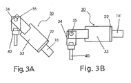
- FIGS 3A and 3B show a gripper arm with a passive joint rotatably mounted thereon as work equipment.
- the working means 30th attached, which consist of a gripper arm 33 and a passive joint 34.
- the Passive joint designed as gripping jaws, is rotatably mounted at the point 35 and by gravity, is a hoist 40, e.g. a metal object, always to hold vertically. This results in a reduced computational effort and a simplified construction compared to a solution with an active joint or a Parallelogram guidance.
- the inventive articulated robot allows because of its smallness, and because of the compact design working in confined spaces.
- it has a maximum mass of 10.5 cm x 33 cm x 33 cm with a radius of impact of about 0.5 m.
- Such a construction results in a dead weight of less than 5.0 kg, preferably less than 3.0 kg.
- the dead weight does not take into account the means of power supply and the means of external computer power.
- the ratio of dead weight to payload is approximately equal to 5.0, which is very advantageous; this with a dead weight of 2.5 kg and a payload of 0.5 kg.
- the working means corresponds to a gripper with two fingers and attached rotatably mounted passive joints according to FIGS. 3A-3B.
- drive elements ie motor-gear units, Maxon DC motors and planetary gear are used for all joints.
- PICs Microchip Embedded Control Solutions Company
- the connection between the boards or sensors and actuators takes place partly with ribbon cables and partly with flexiprints. To reduce the game spiral springs are installed.
- the articulated robot is preferably operated on a stationary base.
Landscapes
- Engineering & Computer Science (AREA)
- Robotics (AREA)
- Mechanical Engineering (AREA)
- Automation & Control Theory (AREA)
- Manipulator (AREA)
- Glass Compositions (AREA)
Description
- Fig. 1
- Basisaufbau eines Knickarmroboters in schematischer Darstellung
- Fig. 2
- Aufbau und Anordnung der Antriebsmittel
- Fig. 3A-3B
- Greiferarm mit drehbar-gelagertem Passiv-Gelenk
Die Achse verläuft im Wesentlichen im Zentrum von Basiselement 1 und Gelenkblock 5. Im oberen Teil des Gelenkblockes 5 liegt eine zweite Achse 7 senkrecht zur Achse 6 angeordnet. Um diese zweite Achse 7 bewegt sich ein Gelenk 8, das von einem zylindrischen Trägerrohr 9, auch 'Oberarm' genannt, umgeben und mit diesem fest verbunden ist. Das Trägerrohr 9 und der Gelenkblock 5 definieren einen zweiten Freiheitsgrad für eine Bewegung von ca. 150° um die Achse 7, was mit dem Drehwinkel α(2) angedeutet ist. Am anderen Ende des Trägerrohres 9 ist ein zweiter Gelenkblock 11 angebracht, durch dessen Zentrum eine dritte Achse 12 parallel zur zweiten Achse 7 verläuft.
Um diese dritte Achse 12 bewegt sich ein Gelenk 13, das von einem zylindrischen Trägerrohr 16, auch 'Vorderarm' genannt, umgeben und mit diesem fest verbunden ist. Das Trägerrohr 16 und der zweite Gelenkblock 11 definieren einen dritten Freiheitsgrad für eine Bewegung von ca. 240° um die Achse 12, was mit dem Drehwinkel α(3) angedeutet ist.
Das Trägerrohr 16 weist nahe dem zweiten Gelenkblock 11 liegend einen flanschförmigen und senkrecht zur Trägerrohrachse liegenden Abschluss 18 auf, durch dessen Zentrum eine vierte Achse 19 parallel zur Trägerrohrachse verläuft.
Die dem Gelenk 13 abgekehrte Seite des Abschlusses 18 weist eine plane Fläche 21 auf, auf der ein Teil 16' des Trägerrohres 16 bündig aufliegt und drehbar um die vierte Achse 19 gelagert ist. Der Teil 16' des Trägerrohres 16 und das Trägerrohr 16 definieren einen vierten Freiheitsgrad für eine Bewegung von etwa 240° um die Achse 19, wodurch ein Drehwinkel α(4) (nicht dargestellt) gebildet wird.
Am anderen Ende des Trägerrohres 16' ist ein Flansch 22 angebracht, durch dessen Zentrum eine fünfte Achse 23 parallel zur vierten Achse 19 verläuft.
Basiselement, Trägerrohre, Gefenkblöcke und Arbeitsmittel sind als Fräs- und Drehteile gefertigt und daher einfach zerlegbar, austauschbar und anwendungsspezifisch anpassbar.
Am Basiselement 1 ist eine äussere Schnittstelle 26 für die serielle Datenübertragung inkl. Stromversorgung angebracht. Von dieser Schnittstelle führt ein Verbindungskabel 27 zu Mitteln der Stromversorgung 28 und ein zweites Verbindungskabel 31 zu Mitteln externer Rechnerleistung 32.
Die Mikrokontroller sind mit jeder Motor-Getriebe-Einheit verbunden (nicht dargestellt) und dienen deren Antrieb und Regelung. Ebenfalls im Befestigungselement 2 befindet sich das Mainboard, auf dem die Verbindungen der Mikrokontroller zusammengeführt werden und auf dem die Verwaltung der äusseren Schnittstelle erfolgt. Die gesamte Leistungselektronik befindet sich auf dem Mainboard und ist vollständig im Roboter integriert, was sich als besonders vorteilhaft erweist.
Ein digitales Bus-System verbindet die elektrischen Antriebsmittel und die Arbeitsmittel 30 mit der äusseren Schnittstelle 26. Damit entfallen empfindliche Analogsignale, wie z.B. gegenüber Magnetfeldern, über lange Strecken. Es resultiert ein störungsfreier Betrieb und damit eine höhere Genauigkeit der Bewegungen. Im weiteren vorteilhaft ist die Möglichkeit einer Erweiterung mit zusätzlichen Kontrollem ohne zusätzliche Leltungen.
Die elektrischen Antriebsmittel können 'In-Circult' programmierbare Flash-Speicher aufweisen, die Firmware-Updates ermöglichen, ohne dass mechanische Eingriffe, resp. ein Austausch von Bauteilen notwendig sind.
Durch die Anordnung der Motor-Getriebe-Einheiten 102 und 103 in den jeweiligen Gelenken liegt der gesamte Antrieb axial in der Gelenkachse, d.h. in der zweiten Achse 7, bzw. der dritten Achse 12. Dadurch entfällt eine Spiel-Übertragung durch andere Gelenke, zudem ergibt dies eine Vereinfachung von Montage und Wartung. Verwendung finden handelsübliche Motor-Getriebe-Einheiten unter Vermeidung von externen, kostspieligen Getrieben.
Zur Lagerung der Gelenke werden Kugel- oder Gleitlager verwendet, da diese eine exakte Führung bei tiefer Reibung erlauben. Dies ist speziell wichtig für die Aufhängung des 4. Freiheitsgrades (Drehung des 'Vorderarms', bzw. des Trägerrohres 16'), damit ein optimaler Druckausgleich bei unsymmetrischer Lastverteilung gewährleistet wird.
Durch die Anordnung der Leistungselektronik innerhalb des Knickarmroboters werden weniger externe Geräte und Kabel benötigt. Die Verkabelung erfolgt intern, wodurch eine mechanische Beeinträchtigung minimiert wird.
Durch die Anordnung der Mikrokontroller möglichst nahe bei den Motor-Getriebe-Einheiten ergeben sich besonders vorteilhaft kurze Kabellängen, von denen die längsten höchstens über ein Gelenk hinwegführen. Im weiteren definiert diese Anordnung gesamthaft eine interne Rechnerleistung, die lokal bei den mechanischen Antriebsmitteln und den Arbeitsmitteln 30 verteilt vorliegt und dadurch eine lokale Intelligenz bildet.
Da jeder Motor-Getriebe-Einheit ein Mikrokontroller für Antrieb und Regelung zugeordnet ist, unterscheidet sich dieser Lösungsansatz von üblichen Robotern, bei denen vielfach von einem externen gemeinsamen Reglerdie gesamten Bewegungen bewerkstelligt werden. Die Vorteile der vorliegenden Lösung sind die Unabhängigkeit der Software verschiedener Motorachsen, was eine höhere Funktionssicherheit bietet, die geringere erforderliche Rechnerleistung pro Chip, bzw. pro Mikrokontroller und weniger Peripherieanschlüsse. Dies führt zu sog. 'LowCost-Mikrokontrollern'.
Da die Positionsregelung pro Achse lokal erfolgt, ergeben sich sehr kurze Reaktionszeiten im Gegensatz zu einer Regelung durch einen zentralen Rechner über einen digitalen Bus. Die Regelparameter sind online durch übergeordnete Steuereinheiten (Mainboard, externer Rechner) änderbar.
Eine derartige Bauweise ergibt ein Eigengewicht von weniger als 5,0 kg, vorzugsweise weniger als 3,0 kg. Beim Eigengewicht sind die Mittel zur Stromversorgung und die Mittel externer Rechnerleistung nicht berücksichtigt. Trotz der Kleinheit hat sich gezeigt, dass das Verhältnis des Eigengewichtes zur Nutzlast etwa gleich 5,0 beträgt, was sehr vorteilhaft ist; dies bei einem Eigengewicht von 2,5 kg und einer Nutzlast von 0,5 kg. Dieses Verhältnis liegt bei sämtlichen bekannten Knickarmrobotern wesentlich ungünstiger.
Er ist vorzüglich geeignet für die interaktive Arbeit mit menschlicher Arbeitskraft und erlaubt ein sogenanntes 'Hand in Hand'-Arbeiten.
Dank modularem Aufbau kann z.B. der Arbeitsbereich durch ein Teleskopstück an Stelle des Trägerrohres 16' in einfacher Weise erweitert werden, wobei die kompakte Bauweise erhalten bleibt.
Als Antriebselemente, d.h. Motor-Getriebe-Einheiten, werden für alle Gelenke Maxon DC-Motoren und Planetengetriebe verwendet. Z.B. für die erste Motor-Getriebe-Einheit: Typ Maxon RE 15 DC 1.6 Watt, Aussendurchmesser 15 mm, Drehmoment 0,5 Nm, Planetengetriebe 455 : 1. Encoder RE 16 Auflösung von 0.05 Grad.
Als lokale Prozessoren für Master und Slave-Boards werden PICs (Microchip Embedded Control Solutions Company) eingesetzt. Die Verbindung zwischen den Boards bzw. Sensoren und Aktuatoren erfolgt teils mit Flachbandkabeln und teils mit Flexiprints. Zur Spielreduktion sind Spiralfedem eingebaut.
Der Knickarmroboter wird bevorzugt auf einer stationären Unterlage betrieben.
Claims (6)
- Knickarmroboter umfassend ein Basiselement (1), mindestens zwei Gelenkblöcke (5, 11), mindestens drei Trägerrohre (9, 16, 16'), Arbeitsmittel (30), mechanische und elektrische Antriebsmittel und Mittel der Stromversorgung (28), wobei die mechanischen Antriebsmittel aus mindestens vier Motor-Getriebe-Einheiten (101, 102, 103, 104, 105) bestehen, die sich im Basiselement (1), in den Gelenkblöcken (5, 11) und in den Trägerrohren (16, 16') befinden, dass die elektrischen Antriebsmittel aus mindestens vier Mikrokontrollem (201, 202, 203, 204, 205) bestehen, die sich im Basiselement (1) und im Trägerrohr (9) befinden, wobei jeder Motor-Getriebe-Einheit ein Mikrokontroller für deren Antrieb und Regelung zugeordnet, mit dieser verbunden und nahe dieser angeordnet ist, dass ein digitales Bus-System (150) die elektrischen Antriebsmittel und die Arbeitsmittel (30) mit einer äusseren, im Basiselement (1) befindlichen Schnittstelle (26) verbindet, dass die Schnittstelle (26) über ein Verbindungskabel (27) mit den Mitteln der Stromversorgung (28) und über ein zweites Verbindungskabel (31) mit den Mitteln externer Rechnerleistung (32) verbunden ist, dass die mechanischen Antriebsmittel für die Bewegungen der Gelenkblöcke (5, 11), der Trägerrohre (9, 16, 16') und der Arbeitsmittel (30) vorgesehen sind und dass die gesamte Leistungselektronik integriert ist, dadurch gekennzeichnet, dass durch die Anordnung der Mikrokontroller (201, 202, 203, 204, 205) eine interne Rechnerleistung gegeben ist, die lokal bei den mechanischen Antriebsmitteln und den Arbeitsmitteln (30) verteilt vorliegt und dadurch eine lokale Intelligenz bildet, dass eine externe Intelligenz in den Mitteln externer Rechnerleistung (32) verfügbar ist und dass beim Übergang von der Motorenachse der elektrischen Antriebsmittel zur Aluminiumkonstruktion mittels Befestigungsschrauben pro Drehachse eine Schutzstelle vorliegt, die Schutz vor übermässiger Krafteinwirkung gewährt.
- Knickarmroboter nach Anspruch 1, dadurch gekennzeichnet, dass die Befestigungsschrauben einem zu grossen Druck nachgeben und nach einer übermässigen Krafteinwirkung von aussen schnell ersetzbar sind.
- Knickarmroboter nach Anspruch 1 oder 2, dadurch gekennzeichnet, dass er eine maximale Leistungsaufnahme von 30 Watt aufweist und dass er auf Grund der limitiert auftretenden Kräfte in einem Raum einsetzbar ist, wo Menschen direkten Zugang haben.
- Knickarmroboter nach einem der Ansprüche 1 - 3, dadurch gekennzeichnet, dass die Arbeitsmittel (30) als Sensoren IR-Sensoren, lokale Kraftsensoren, Leitfähigkeitssensoren, Dehnungssensoren, Ultraschallsensoren und/oder Laser aufweisen.
- Knickarmroboter nach Anspruch 4, dadurch gekennzeichnet, dass Sensoren verschiedener Modalität vorliegen, die eine Sensor-Redundanz bilden, die die Lernfähigkeit erhöht.
- Knickarmroboter nach einem der Ansprüche 1 - 5, dadurch gekennzeichnet, dass für die Bewegungen der Gelenkblöcke (5, 11), der Trägerrohre (9, 16, 16') und der Arbeitsmittel (30) adaptive Regelungen und Vorsteuerungsparameter vorgesehen sind, wobei für deren Betrieb, bzw. deren Berechnung die Mittel externer Rechnerleistung (32) verfügbar sind und mittels Algorithmen der künstlichen Intelligenz die Lernfähigkeit gegeben ist.
Applications Claiming Priority (3)
| Application Number | Priority Date | Filing Date | Title |
|---|---|---|---|
| CH7312001 | 2001-04-22 | ||
| CH731012001 | 2001-04-22 | ||
| PCT/CH2002/000216 WO2002086637A1 (de) | 2001-04-22 | 2002-04-19 | Knickarmroboter |
Publications (2)
| Publication Number | Publication Date |
|---|---|
| EP1381925A1 EP1381925A1 (de) | 2004-01-21 |
| EP1381925B1 true EP1381925B1 (de) | 2005-08-31 |
Family
ID=4532378
Family Applications (1)
| Application Number | Title | Priority Date | Filing Date |
|---|---|---|---|
| EP02712712A Expired - Lifetime EP1381925B1 (de) | 2001-04-22 | 2002-04-19 | Knickarmroboter |
Country Status (7)
| Country | Link |
|---|---|
| US (1) | US20060177295A1 (de) |
| EP (1) | EP1381925B1 (de) |
| JP (1) | JP2004520953A (de) |
| KR (1) | KR20040007502A (de) |
| AT (1) | ATE303622T1 (de) |
| DE (1) | DE50204091D1 (de) |
| WO (1) | WO2002086637A1 (de) |
Families Citing this family (34)
| Publication number | Priority date | Publication date | Assignee | Title |
|---|---|---|---|---|
| DE102005046838A1 (de) * | 2005-09-29 | 2007-04-05 | Atec Pharmatechnik Gmbh | Vorrichtung zum Heben und Drehen von Behältern in einer Reinraumumgebung |
| US7979160B2 (en) * | 2007-07-31 | 2011-07-12 | Spirit Aerosystems, Inc. | System and method for robotic accuracy improvement |
| JP2009297810A (ja) * | 2008-06-11 | 2009-12-24 | Panasonic Corp | マニピュレータの姿勢制御装置および姿勢制御方法 |
| JP2013507171A (ja) * | 2009-10-09 | 2013-03-04 | ドクサ アクティボラグ | 二バインダシステムを含む簡略化された化学結合されたセラミック生体材料 |
| DE102010013923A1 (de) * | 2010-04-01 | 2011-10-06 | Wittenstein Ag | Autarkes Manipulatorelement |
| KR101329640B1 (ko) | 2011-12-13 | 2013-11-14 | 한양대학교 산학협력단 | 작업 솜씨를 학습하는 방법 및 이를 이용한 로봇 |
| KR101329642B1 (ko) * | 2012-02-24 | 2013-11-14 | 한양대학교 산학협력단 | 작업 솜씨 학습을 위한 모델링 방법 및 이를 이용한 로봇 |
| BR102012031940B1 (pt) * | 2012-12-14 | 2021-07-20 | Gd Do Brasil Maquinas De Embalar Ltda | Unidade de robô de transferência |
| CN104470689B (zh) * | 2013-01-17 | 2017-10-13 | 松下知识产权经营株式会社 | 产业用机器人 |
| CN103351177A (zh) * | 2013-07-02 | 2013-10-16 | 佛山市新鹏陶瓷机械有限公司 | 一种自动化喷釉无动力测量关节臂 |
| JP6502956B2 (ja) | 2014-03-17 | 2019-04-17 | エフアンドピー ロボテックス アクチェンゲゼルシャフト | ロボット・システム用グリッパ・フィンガのグリッパ・チップを置き換えるためのアセンブリ・デバイス |
| EP3119564A1 (de) | 2014-03-17 | 2017-01-25 | F&P Robotics AG | Greiferfinger, greiferspitze und greiferbacke, sowie ein robotersystem |
| CN104023204A (zh) * | 2014-05-15 | 2014-09-03 | 李明科 | 一种施工场所用高空探头 |
| JP6677441B2 (ja) | 2014-10-20 | 2020-04-08 | 株式会社デンソーウェーブ | ロボット、ロボットの形状設計方法 |
| ES2976182T3 (es) | 2015-09-09 | 2024-07-26 | Berkshire Grey Operating Company Inc | Sistema y método para proporcionar una iluminación comunicativa dinámica en un entorno robótico |
| CN106371379A (zh) * | 2016-12-07 | 2017-02-01 | 上海电气集团股份有限公司 | 一种机器人的运动控制模块 |
| US10941000B2 (en) | 2017-03-23 | 2021-03-09 | Berkshire Grey, Inc. | Systems and methods for processing objects, including automated linear processing stations |
| JP3228266U (ja) | 2017-06-19 | 2020-10-22 | ジョンルイ フーニン ロボティクス (シェンヤン) カンパニー リミテッド | 人との社会的相互作用のための行為を実施するように構成されたロボット |
| GB2564480B (en) * | 2017-07-14 | 2022-02-23 | Peak Analysis And Automation Ltd | Robotic positioning system |
| CN109253874B (zh) * | 2018-10-19 | 2020-03-31 | 日照职业技术学院 | 一种机器人手臂灵活度检测装置 |
| US12408929B2 (en) | 2019-09-27 | 2025-09-09 | Globus Medical, Inc. | Systems and methods for navigating a pin guide driver |
| US11426178B2 (en) | 2019-09-27 | 2022-08-30 | Globus Medical Inc. | Systems and methods for navigating a pin guide driver |
| US11890066B2 (en) | 2019-09-30 | 2024-02-06 | Globus Medical, Inc | Surgical robot with passive end effector |
| US11864857B2 (en) | 2019-09-27 | 2024-01-09 | Globus Medical, Inc. | Surgical robot with passive end effector |
| DE102020113249A1 (de) | 2020-05-15 | 2021-11-18 | Bayerische Motoren Werke Aktiengesellschaft | Baukastensystem für eine Handhabungsvorrichtung sowie Handhabungsvorrichtung |
| CN111843990B (zh) * | 2020-06-22 | 2022-08-30 | 安徽科汇钢结构工程有限公司 | 一种可折叠机械臂钢架结构 |
| CN112720423B (zh) * | 2021-01-12 | 2022-03-25 | 山东理工大学 | 一种含双平行四边形的单层三段导轨式平面机器人 |
| CN112720424B (zh) * | 2021-01-12 | 2022-03-25 | 山东理工大学 | 一种含平行四边形的双层三段导轨式平面机器人 |
| CN112975990B (zh) * | 2021-04-25 | 2021-07-30 | 呜啦啦(广州)科技有限公司 | 一种机械关节同步控制方法及系统 |
| CN115648231B (zh) * | 2022-12-29 | 2023-03-21 | 无锡黎曼机器人科技有限公司 | 一种轮胎胎坯的尺寸位置识别和抓取控制方法及控制系统 |
| CN116572557B (zh) * | 2023-05-24 | 2025-09-30 | 武汉大学 | 复现人工铺放二维织物的信息采集系统及复现方法 |
| CN117948064A (zh) * | 2024-03-22 | 2024-04-30 | 济南悦创液压机械制造有限公司 | 一种曲臂吊自动上料装置 |
| KR102831278B1 (ko) * | 2025-03-28 | 2025-07-08 | (주)빅텍스 | 외장형 밸런싱 웨이트 구조 및 이를 포함하는 매니퓰레이터 |
| CN120715919B (zh) * | 2025-09-01 | 2026-01-06 | 深圳市盛泰奇科技有限公司 | 一种人型机器人四肢关节驱动器的协同控制方法及系统 |
Family Cites Families (17)
| Publication number | Priority date | Publication date | Assignee | Title |
|---|---|---|---|---|
| US4467436A (en) * | 1981-10-26 | 1984-08-21 | United States Robots, Inc. | Robot arm controller with common bus memory |
| US4641251A (en) * | 1982-02-16 | 1987-02-03 | Inoue-Japax Research Incorporated | Robot |
| US4518308A (en) * | 1982-03-01 | 1985-05-21 | Acrobe Technology Inc. | Manipulator apparatus |
| DE3414067A1 (de) * | 1984-04-13 | 1985-11-07 | GdA Gesellschaft für digitale Automation mbH, 8000 München | Ueberlastsicherung |
| US4698775A (en) * | 1985-05-17 | 1987-10-06 | Flexible Manufacturing Systems, Inc. | Self-contained mobile reprogrammable automation device |
| JPS621004A (ja) * | 1985-05-30 | 1987-01-07 | Matsushita Electric Ind Co Ltd | ロボツト |
| US5219264A (en) * | 1986-09-19 | 1993-06-15 | Texas Instruments Incorporated | Mobile robot on-board vision system |
| JPH02145282A (ja) * | 1988-11-25 | 1990-06-04 | Agency Of Ind Science & Technol | 人間類似型上肢機構 |
| US4990839A (en) * | 1988-12-09 | 1991-02-05 | Schonlau William J | Modular robotic system |
| US5005147A (en) * | 1988-12-30 | 1991-04-02 | The United States Of America As Represented By The Administrator, The National Aeronautics And Space Administration | Method and apparatus for sensor fusion |
| DE4000348A1 (de) * | 1989-03-06 | 1990-09-13 | Hewlett Packard Co | Vorrichtung und verfahren zum ueberwachen der bewegungen eines vielgelenkigen roboters |
| US5724264A (en) * | 1993-07-16 | 1998-03-03 | Immersion Human Interface Corp. | Method and apparatus for tracking the position and orientation of a stylus and for digitizing a 3-D object |
| DE19521833C2 (de) * | 1995-06-16 | 2002-04-25 | Ruthmann Anton Gmbh & Co | Handhabungsgerät für zu demontierende Alt-Kraftfahrzeuge |
| US5733096A (en) * | 1995-09-13 | 1998-03-31 | Silicon Valley Group, Inc. | Multi-stage telescoping structure |
| US6331181B1 (en) * | 1998-12-08 | 2001-12-18 | Intuitive Surgical, Inc. | Surgical robotic tools, data architecture, and use |
| GB9713765D0 (en) * | 1997-07-01 | 1997-09-03 | Engineering Services Inc | Reconfigurable mudular drive system |
| DE19814630B4 (de) * | 1998-03-26 | 2011-09-29 | Carl Zeiss | Verfahren und Vorrichtung zum handgesteuerten Führen eines Werkzeuges in einem vorgegebenen Bewegungsbereich |
-
2002
- 2002-04-19 EP EP02712712A patent/EP1381925B1/de not_active Expired - Lifetime
- 2002-04-19 US US10/475,325 patent/US20060177295A1/en not_active Abandoned
- 2002-04-19 DE DE50204091T patent/DE50204091D1/de not_active Expired - Lifetime
- 2002-04-19 AT AT02712712T patent/ATE303622T1/de not_active IP Right Cessation
- 2002-04-19 JP JP2002584097A patent/JP2004520953A/ja active Pending
- 2002-04-19 WO PCT/CH2002/000216 patent/WO2002086637A1/de not_active Ceased
- 2002-04-19 KR KR10-2003-7013790A patent/KR20040007502A/ko not_active Withdrawn
Also Published As
| Publication number | Publication date |
|---|---|
| DE50204091D1 (de) | 2005-10-06 |
| KR20040007502A (ko) | 2004-01-24 |
| HK1062648A1 (en) | 2004-11-19 |
| WO2002086637A1 (de) | 2002-10-31 |
| ATE303622T1 (de) | 2005-09-15 |
| US20060177295A1 (en) | 2006-08-10 |
| JP2004520953A (ja) | 2004-07-15 |
| EP1381925A1 (de) | 2004-01-21 |
Similar Documents
| Publication | Publication Date | Title |
|---|---|---|
| EP1381925B1 (de) | Knickarmroboter | |
| DE102010045531B4 (de) | Serielles elastisches Drehstellglied | |
| DE102014222809B3 (de) | Event-basierte Redundanzwinkelkonfiguartion für Gelenkarmroboter | |
| DE102010007631B4 (de) | Parallelroboter mit einem Handgelenkabschnitt mit drei Freiheitsgraden | |
| DE102004002416B4 (de) | Knickarmroboter | |
| DE102010052418B4 (de) | Kraftbegrenzungseinrichtung und Verfahren | |
| EP2666600B1 (de) | Industrieroboter mit in einem Handgrundgehäuse sich erstreckenden Antrieben | |
| DE102014225537B4 (de) | Robotervorrichtung, robotersteuerverfahren, programm und aufzeichnungsmedium | |
| DE2530261C2 (de) | Programmiereinrichtung für einen Manipulator | |
| Tavakoli et al. | A hybrid pole climbing and manipulating robot with minimum DOFs for construction and service applications | |
| DE102010027280A1 (de) | Roboterintegrierter Arbeitsplatz | |
| DE102010045526B4 (de) | Verpackung von Stellgliedern und Elektronik für eine extrinsische humanoide Hand | |
| DE2745932A1 (de) | Manipulator | |
| DE102021130823B4 (de) | Ausgleichsmechanismus für roboterhilfsgerät | |
| DE3918587A1 (de) | Umkonfigurierbarer gelenkiger roboterarm | |
| EP0260219A1 (de) | Roboterarm | |
| DE102019215850A1 (de) | Roboter und erstes Armglied | |
| EP2540454B1 (de) | Hybridroboter auf der Basis von drei Linearaktoren deren Achsen sich schneiden, eines Parallelitätshalters, eines multifunktionalen Raumgelenkes, eines Mehrachsenraumgelenkes und einer Raumorientierungseinheit | |
| DE102018206473A1 (de) | Roboter | |
| WO2022053664A1 (de) | Roboter | |
| DE102021129897B4 (de) | Modulare Robotervorrichtung und Verfahren zum Betreiben einer modularen Robotervorrichtung | |
| DE112021006054T5 (de) | Arbeitsgerät | |
| DE102018207919B3 (de) | Robotersteuerung | |
| EP4592039B1 (de) | Manipulator und roboteraufbau | |
| WO2022112044A1 (de) | Mehrgliedrige aktuierte kinematik |
Legal Events
| Date | Code | Title | Description |
|---|---|---|---|
| PUAI | Public reference made under article 153(3) epc to a published international application that has entered the european phase |
Free format text: ORIGINAL CODE: 0009012 |
|
| 17P | Request for examination filed |
Effective date: 20031118 |
|
| AK | Designated contracting states |
Kind code of ref document: A1 Designated state(s): AT BE CH CY DE DK ES FI FR GB GR IE IT LI LU MC NL PT SE TR |
|
| AX | Request for extension of the european patent |
Extension state: LT LV RO SI |
|
| RIN1 | Information on inventor provided before grant (corrected) |
Inventor name: GFELLER, CHRISTIAN Inventor name: BRETSCHER, THOMAS Inventor name: FRUEH, HANSRUEDI |
|
| 17Q | First examination report despatched |
Effective date: 20040608 |
|
| REG | Reference to a national code |
Ref country code: HK Ref legal event code: DE Ref document number: 1062658 Country of ref document: HK |
|
| GRAP | Despatch of communication of intention to grant a patent |
Free format text: ORIGINAL CODE: EPIDOSNIGR1 |
|
| GRAS | Grant fee paid |
Free format text: ORIGINAL CODE: EPIDOSNIGR3 |
|
| GRAA | (expected) grant |
Free format text: ORIGINAL CODE: 0009210 |
|
| AK | Designated contracting states |
Kind code of ref document: B1 Designated state(s): AT BE CH CY DE DK ES FI FR GB GR IE IT LI LU MC NL PT SE TR |
|
| PG25 | Lapsed in a contracting state [announced via postgrant information from national office to epo] |
Ref country code: IT Free format text: LAPSE BECAUSE OF FAILURE TO SUBMIT A TRANSLATION OF THE DESCRIPTION OR TO PAY THE FEE WITHIN THE PRESCRIBED TIME-LIMIT;WARNING: LAPSES OF ITALIAN PATENTS WITH EFFECTIVE DATE BEFORE 2007 MAY HAVE OCCURRED AT ANY TIME BEFORE 2007. THE CORRECT EFFECTIVE DATE MAY BE DIFFERENT FROM THE ONE RECORDED. Effective date: 20050831 Ref country code: IE Free format text: LAPSE BECAUSE OF FAILURE TO SUBMIT A TRANSLATION OF THE DESCRIPTION OR TO PAY THE FEE WITHIN THE PRESCRIBED TIME-LIMIT Effective date: 20050831 Ref country code: FI Free format text: LAPSE BECAUSE OF FAILURE TO SUBMIT A TRANSLATION OF THE DESCRIPTION OR TO PAY THE FEE WITHIN THE PRESCRIBED TIME-LIMIT Effective date: 20050831 Ref country code: NL Free format text: LAPSE BECAUSE OF FAILURE TO SUBMIT A TRANSLATION OF THE DESCRIPTION OR TO PAY THE FEE WITHIN THE PRESCRIBED TIME-LIMIT Effective date: 20050831 |
|
| REG | Reference to a national code |
Ref country code: GB Ref legal event code: FG4D Free format text: NOT ENGLISH Ref country code: CH Ref legal event code: EP |
|
| REG | Reference to a national code |
Ref country code: IE Ref legal event code: FG4D Free format text: LANGUAGE OF EP DOCUMENT: GERMAN |
|
| REF | Corresponds to: |
Ref document number: 50204091 Country of ref document: DE Date of ref document: 20051006 Kind code of ref document: P |
|
| PG25 | Lapsed in a contracting state [announced via postgrant information from national office to epo] |
Ref country code: SE Free format text: LAPSE BECAUSE OF FAILURE TO SUBMIT A TRANSLATION OF THE DESCRIPTION OR TO PAY THE FEE WITHIN THE PRESCRIBED TIME-LIMIT Effective date: 20051130 Ref country code: DK Free format text: LAPSE BECAUSE OF FAILURE TO SUBMIT A TRANSLATION OF THE DESCRIPTION OR TO PAY THE FEE WITHIN THE PRESCRIBED TIME-LIMIT Effective date: 20051130 Ref country code: GR Free format text: LAPSE BECAUSE OF FAILURE TO SUBMIT A TRANSLATION OF THE DESCRIPTION OR TO PAY THE FEE WITHIN THE PRESCRIBED TIME-LIMIT Effective date: 20051130 |
|
| REG | Reference to a national code |
Ref country code: CH Ref legal event code: NV Representative=s name: DILTEC AG |
|
| GBT | Gb: translation of ep patent filed (gb section 77(6)(a)/1977) |
Effective date: 20051212 |
|
| REG | Reference to a national code |
Ref country code: HK Ref legal event code: GR Ref document number: 1062658 Country of ref document: HK |
|
| PG25 | Lapsed in a contracting state [announced via postgrant information from national office to epo] |
Ref country code: PT Free format text: LAPSE BECAUSE OF FAILURE TO SUBMIT A TRANSLATION OF THE DESCRIPTION OR TO PAY THE FEE WITHIN THE PRESCRIBED TIME-LIMIT Effective date: 20060223 |
|
| NLV1 | Nl: lapsed or annulled due to failure to fulfill the requirements of art. 29p and 29m of the patents act | ||
| REG | Reference to a national code |
Ref country code: IE Ref legal event code: FD4D |
|
| PG25 | Lapsed in a contracting state [announced via postgrant information from national office to epo] |
Ref country code: MC Free format text: LAPSE BECAUSE OF NON-PAYMENT OF DUE FEES Effective date: 20060430 Ref country code: BE Free format text: LAPSE BECAUSE OF NON-PAYMENT OF DUE FEES Effective date: 20060430 |
|
| PLBE | No opposition filed within time limit |
Free format text: ORIGINAL CODE: 0009261 |
|
| STAA | Information on the status of an ep patent application or granted ep patent |
Free format text: STATUS: NO OPPOSITION FILED WITHIN TIME LIMIT |
|
| 26N | No opposition filed |
Effective date: 20060601 |
|
| EN | Fr: translation not filed | ||
| PG25 | Lapsed in a contracting state [announced via postgrant information from national office to epo] |
Ref country code: FR Free format text: LAPSE BECAUSE OF FAILURE TO SUBMIT A TRANSLATION OF THE DESCRIPTION OR TO PAY THE FEE WITHIN THE PRESCRIBED TIME-LIMIT Effective date: 20061027 |
|
| BERE | Be: lapsed |
Owner name: NEURONICS A.G. Effective date: 20060430 |
|
| PG25 | Lapsed in a contracting state [announced via postgrant information from national office to epo] |
Ref country code: LU Free format text: LAPSE BECAUSE OF NON-PAYMENT OF DUE FEES Effective date: 20060419 Ref country code: TR Free format text: LAPSE BECAUSE OF FAILURE TO SUBMIT A TRANSLATION OF THE DESCRIPTION OR TO PAY THE FEE WITHIN THE PRESCRIBED TIME-LIMIT Effective date: 20050831 |
|
| PG25 | Lapsed in a contracting state [announced via postgrant information from national office to epo] |
Ref country code: FR Free format text: LAPSE BECAUSE OF FAILURE TO SUBMIT A TRANSLATION OF THE DESCRIPTION OR TO PAY THE FEE WITHIN THE PRESCRIBED TIME-LIMIT Effective date: 20050831 Ref country code: CY Free format text: LAPSE BECAUSE OF FAILURE TO SUBMIT A TRANSLATION OF THE DESCRIPTION OR TO PAY THE FEE WITHIN THE PRESCRIBED TIME-LIMIT Effective date: 20050831 |
|
| PG25 | Lapsed in a contracting state [announced via postgrant information from national office to epo] |
Ref country code: ES Free format text: LAPSE BECAUSE OF NON-PAYMENT OF DUE FEES Effective date: 20060430 |
|
| PGFP | Annual fee paid to national office [announced via postgrant information from national office to epo] |
Ref country code: GB Payment date: 20100317 Year of fee payment: 9 |
|
| PGFP | Annual fee paid to national office [announced via postgrant information from national office to epo] |
Ref country code: AT Payment date: 20100430 Year of fee payment: 9 Ref country code: DE Payment date: 20100414 Year of fee payment: 9 |
|
| REG | Reference to a national code |
Ref country code: CH Ref legal event code: PUE Owner name: KAMAKO BETEILIGUNGEN AG Free format text: NEURONICS AG#TECHNOPARKSTRASSE 1#CH-8005 ZUERICH (CH) -TRANSFER TO- KAMAKO BETEILIGUNGEN AG#ZUERCHERSTRASSE 49#8853 LACHEN (CH) $ WALTER VILLIGER#PARADIESSTRASSE 25#8645 RAPPERSWIL-JONA (CH) Ref country code: CH Ref legal event code: NV Representative=s name: LENZ & STAEHELIN |
|
| GBPC | Gb: european patent ceased through non-payment of renewal fee |
Effective date: 20110419 |
|
| REG | Reference to a national code |
Ref country code: AT Ref legal event code: MM01 Ref document number: 303622 Country of ref document: AT Kind code of ref document: T Effective date: 20110419 |
|
| REG | Reference to a national code |
Ref country code: DE Ref legal event code: R081 Ref document number: 50204091 Country of ref document: DE Owner name: VILLIGER, WALTER, CH Free format text: FORMER OWNER: NEURONICS AG, ZUERICH, CH Effective date: 20111130 Ref country code: DE Ref legal event code: R081 Ref document number: 50204091 Country of ref document: DE Owner name: KAMAKO BETEILIGUNGEN AG, CH Free format text: FORMER OWNER: NEURONICS AG, ZUERICH, CH Effective date: 20111130 |
|
| PG25 | Lapsed in a contracting state [announced via postgrant information from national office to epo] |
Ref country code: DE Free format text: LAPSE BECAUSE OF NON-PAYMENT OF DUE FEES Effective date: 20111101 |
|
| PG25 | Lapsed in a contracting state [announced via postgrant information from national office to epo] |
Ref country code: AT Free format text: LAPSE BECAUSE OF NON-PAYMENT OF DUE FEES Effective date: 20110419 Ref country code: GB Free format text: LAPSE BECAUSE OF NON-PAYMENT OF DUE FEES Effective date: 20110419 |
|
| REG | Reference to a national code |
Ref country code: DE Ref legal event code: R119 Ref document number: 50204091 Country of ref document: DE Effective date: 20111101 |
|
| PGFP | Annual fee paid to national office [announced via postgrant information from national office to epo] |
Ref country code: CH Payment date: 20130410 Year of fee payment: 12 |
|
| REG | Reference to a national code |
Ref country code: CH Ref legal event code: PL |
|
| PG25 | Lapsed in a contracting state [announced via postgrant information from national office to epo] |
Ref country code: CH Free format text: LAPSE BECAUSE OF NON-PAYMENT OF DUE FEES Effective date: 20140430 Ref country code: LI Free format text: LAPSE BECAUSE OF NON-PAYMENT OF DUE FEES Effective date: 20140430 |