EP1380375B1 - Tangential-Wendeschneidplatte - Google Patents
Tangential-Wendeschneidplatte Download PDFInfo
- Publication number
- EP1380375B1 EP1380375B1 EP03013764A EP03013764A EP1380375B1 EP 1380375 B1 EP1380375 B1 EP 1380375B1 EP 03013764 A EP03013764 A EP 03013764A EP 03013764 A EP03013764 A EP 03013764A EP 1380375 B1 EP1380375 B1 EP 1380375B1
- Authority
- EP
- European Patent Office
- Prior art keywords
- cutting edges
- main cutting
- cutting blade
- tangential
- plane
- Prior art date
- Legal status (The legal status is an assumption and is not a legal conclusion. Google has not performed a legal analysis and makes no representation as to the accuracy of the status listed.)
- Expired - Fee Related
Links
Images


Classifications
-
- B—PERFORMING OPERATIONS; TRANSPORTING
- B23—MACHINE TOOLS; METAL-WORKING NOT OTHERWISE PROVIDED FOR
- B23C—MILLING
- B23C5/00—Milling-cutters
- B23C5/16—Milling-cutters characterised by physical features other than shape
- B23C5/20—Milling-cutters characterised by physical features other than shape with removable cutter bits or teeth or cutting inserts
- B23C5/22—Securing arrangements for bits or teeth or cutting inserts
-
- B—PERFORMING OPERATIONS; TRANSPORTING
- B23—MACHINE TOOLS; METAL-WORKING NOT OTHERWISE PROVIDED FOR
- B23C—MILLING
- B23C2200/00—Details of milling cutting inserts
- B23C2200/12—Side or flank surfaces
- B23C2200/123—Side or flank surfaces curved
-
- B—PERFORMING OPERATIONS; TRANSPORTING
- B23—MACHINE TOOLS; METAL-WORKING NOT OTHERWISE PROVIDED FOR
- B23C—MILLING
- B23C2200/00—Details of milling cutting inserts
- B23C2200/12—Side or flank surfaces
- B23C2200/125—Side or flank surfaces discontinuous
-
- B—PERFORMING OPERATIONS; TRANSPORTING
- B23—MACHINE TOOLS; METAL-WORKING NOT OTHERWISE PROVIDED FOR
- B23C—MILLING
- B23C2200/00—Details of milling cutting inserts
- B23C2200/28—Angles
- B23C2200/284—Negative clearance angles
-
- B—PERFORMING OPERATIONS; TRANSPORTING
- B23—MACHINE TOOLS; METAL-WORKING NOT OTHERWISE PROVIDED FOR
- B23C—MILLING
- B23C2200/00—Details of milling cutting inserts
- B23C2200/36—Other features of the milling insert not covered by B23C2200/04 - B23C2200/32
- B23C2200/367—Mounted tangentially, i.e. where the rake face is not the face with largest area
-
- B—PERFORMING OPERATIONS; TRANSPORTING
- B23—MACHINE TOOLS; METAL-WORKING NOT OTHERWISE PROVIDED FOR
- B23C—MILLING
- B23C2210/00—Details of milling cutters
- B23C2210/08—Side or top views of the cutting edge
- B23C2210/088—Cutting edges with a wave form
-
- Y—GENERAL TAGGING OF NEW TECHNOLOGICAL DEVELOPMENTS; GENERAL TAGGING OF CROSS-SECTIONAL TECHNOLOGIES SPANNING OVER SEVERAL SECTIONS OF THE IPC; TECHNICAL SUBJECTS COVERED BY FORMER USPC CROSS-REFERENCE ART COLLECTIONS [XRACs] AND DIGESTS
- Y10—TECHNICAL SUBJECTS COVERED BY FORMER USPC
- Y10T—TECHNICAL SUBJECTS COVERED BY FORMER US CLASSIFICATION
- Y10T407/00—Cutters, for shaping
- Y10T407/23—Cutters, for shaping including tool having plural alternatively usable cutting edges
- Y10T407/235—Cutters, for shaping including tool having plural alternatively usable cutting edges with integral chip breaker, guide or deflector
-
- Y—GENERAL TAGGING OF NEW TECHNOLOGICAL DEVELOPMENTS; GENERAL TAGGING OF CROSS-SECTIONAL TECHNOLOGIES SPANNING OVER SEVERAL SECTIONS OF THE IPC; TECHNICAL SUBJECTS COVERED BY FORMER USPC CROSS-REFERENCE ART COLLECTIONS [XRACs] AND DIGESTS
- Y10—TECHNICAL SUBJECTS COVERED BY FORMER USPC
- Y10T—TECHNICAL SUBJECTS COVERED BY FORMER US CLASSIFICATION
- Y10T407/00—Cutters, for shaping
- Y10T407/24—Cutters, for shaping with chip breaker, guide or deflector
- Y10T407/245—Cutters, for shaping with chip breaker, guide or deflector comprising concave surface in cutting face of tool
Definitions
- the invention relates to a tangential indexable insert after Preamble of claim 1.
- EP 0 769 341 A1 discloses an indexable insert according to the generic term of claim 1 become known at the im Area of their two side faces and in the area of their two end faces to each Deck and base surface is formed towards a cutting edge. All to the side surfaces and the end surfaces adjacent cutting edges have the same cutting geometry. In the cover and base areas and along the two side surfaces and along the two end faces each Spanmulden are incorporated. The lengths Cutting edges have a curved ground contour.
- indexable insert with a substantially cubic body became known, with eight usable cutting edges Is provided. It has two parallel arranged plane and one Attachment hole penetrated larger areas and four adjacent thereto each Side surfaces on, with the larger areas over a rounded edge in The smaller end surfaces merge, so that on the long side about a quarter circle trained cutting edges as boundary lines to the end surfaces in the corner area result.
- the long cutting edges are called borderlines between the larger surfaces and the respective adjacent longitudinal surface arcuate curved, so that a mirror-symmetrical to the longitudinal center and transverse center plane Body results.
- Such indexable inserts are on a milling body attached tangentially.
- a tangential cutting insert has become known with a effective front surface, upper and lower major cutting edges, minor side cutting edges and intersecting corner cutting edges. They point to the formed on the front surface clamping surfaces, which differ from their assigned Cutting edges extend inwardly with respect to the cutting insert, wherein the cutting insert has an imaginary reference plane defined by endpoints its corner cutting edges runs. Each main cutting edge extends from their associated corner edges with respect to the insert inwards and from away from the reference plane.
- the invention has for its object to provide a tangential indexable insert create that can be used eight times.
- the tangential indexable insert according to the invention has a prismatic Body on, of two opposite identically shaped first surfaces and four identically shaped intermediate side surfaces is limited. each The first surface forms four equally long main cutting edges with the side surfaces. All Main cutting edges have an identical geometry.
- the inventive Indexable insert also has a raised ridge with a flat surface on, wherein the four webs are arranged symmetrically to a center plane, which passes through the side surfaces.
- Indexable insert with the help of a passing through a central through hole Clamping screw is a seat of the first surface on a seat of the cutter body, while at least one web with its surface at another Seat abuts.
- a respective 90 ° rotation of the invention Insert each have a main cutting edge used.
- By a 180 ° rotation of the indexable insert then takes place on the other first surface, so in turn by 90 ° turns each one assigned cutting edge can be used.
- the rake surfaces to the main cutting edges are formed in the side surfaces by corresponding grooves on both sides of the bridge.
- the open spaces are at the first Surfaces formed in the form of the spherical surface sections, which are at the main cutting edges adjoin.
- the first surfaces facing each other are spherical Build up. According to one embodiment of the invention, however, the to the Limiting bore adjacent annular surface portions of the first surfaces plane-parallel. In this area, the investment of the indexable insert takes place on the seat, in which the receiving bore for the screw is molded.
- the secondary or plan cutting by grooving the corner areas between the side surfaces and a Planfase generated at the end of the main cutting edges.
- the Planfase concave i. provided with a radius.
- a Such Planfase running away to the rear allows a soft penetration into the material.
- the arcuate cutting edge which results from the surface shape of the first two surfaces, also allows a soft cut.
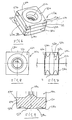
- FIGS. 1 to 4 show a tangential indexable insert 10.
- she has opposite first surfaces 12, 14, which of a through hole 16 are pierced.
- the through hole 16 is symmetrical to a center plane 18, which runs approximately parallel to the side surfaces 12, 14.
- Between the first surfaces 12, 14 are four offset by approximately 90 ° arranged side surfaces 20.
- the side surfaces 20 are formed by a central raised ridge 22 and flutes 24, 26 on both sides of the ridge.
- Main cutting edges 28 are formed.
- FIGS. 1 and 2 are the main cutting edges 28 in plan view of the first surfaces 12, 14 straight, however arcuately curved in the side view.
- This curvature arises from the fact that the first surfaces 12, 14 in the adjacent area to the main cutting edges 28 spherical surface sections 30 form.
- the perforation 16 surrounds on both first surfaces 12, 14 a planar annular surface portion 32, wherein the annular surface portions 32 of both first surfaces 12, 14 plane-parallel to each other are.
- grooves 34 which with Planfasen 36 at the ends of the cutting edges 28 secondary or edge cutting 38th to shape.
- the chamfers 36 may be radiused, i. a convex Have curvature.
- the indexable insert 10 shown in eight different Insert positions each with a main cutting edge 28 and a minor cutting edge 38 are used.
- FIG. 5 One possible use is shown in Fig. 5, in which several indexable inserts 10 are attached to a carrier body 40.
- the carrier body has pocket-shaped receptacles for the indexable inserts 10, which has a first seat 42 form and a second seat 44.
- On the seat 42 comes respectively an annular surface portion 32 of the first surfaces 12, 14 for conditioning.
- At the second Seat 44 is in each case a web with its flat surface 22 to the plant.
- a third seat 46 allows the installation of a second web of the indexable insert.
- the attachment is made by means of a screw 48, which through the Through hole 16 of the insert 10 is guided and in a not shown Threaded hole in the seat 42 is screwed.
- the axis of rotation of the cutter body is shown at 50.
- the indexable inserts 10 are in tangential arrangement and an arrangement at an angle of 45 °. The latter is but not condition.
- the setting angle ⁇ can be chosen arbitrarily within limits become.
- the flutes 24, 26 rake surfaces 50a.
- the Open spaces are formed by the spherical surface portions 30.
- the open space for the cutting edges 38 are formed by the Planfasen 36.
- the fillets 24, 26 are also not straight, but provided with a radius, so that they are concave in the longitudinal direction, i. in the middle of their deepest Have a spot and flatten to the ends a bit.
- FIGS. 6 to 9 show a tangential indexable insert 10a.
- she has opposite first surfaces 12a, 14a, which from a through hole 16a are pierced.
- the through hole 16a is symmetrical to a center plane 18a, which is approximately parallel to the side surfaces 12a, 14a runs.
- Between the first surfaces 12a, 14a are four approximately 90 ° staggered side surfaces 20a.
- the side surfaces 20a are formed by a central raised ridge 22a and flutes 24a, 26a on both sides of the footbridge. Between the flutes 24a, 26a and the associated first surface 12a and 14a, respectively, main cutting edges 28a are formed.
- the major cutting edges 28a are in plan view of the first surfaces 12a, 14a straight, but arcuately curved in the side view. This curvature results from the fact that the first surfaces 12a, 14a in the adjacent area to the main cutting edges 28a form spherical surface portions 30a.
- the puncture 16a surrounds on both first surfaces 12a, 14a a planar annular surface portion 32a, wherein the annular surface portions 32a of both first surfaces 12a, 14a are plane-parallel.
- the webs 22a are a flat surface symmetrical to the center plane 18a. This also applies to the fillets 20a on both sides of the web 22a too.
- the grooves 20a overflow Surface portions 27 in the edge 39 a.
- the surface sections are flat but they do not have to be shown.
- the indexable insert 10a shown in eight different Insert positions each with a main cutting edge 28a and a minor cutting edge 38a are used.
- the application is similar to that shown in Fig. 5, by several indexable inserts 10a are attached to a carrier body.
- the carrier body has pocket-shaped receptacles for the indexable inserts 10a, which form a first seat and a second seat.
- first seat In each case, an annular surface portion 32a of the first surfaces 12a, 14a comes to rest.
- second seat is in each case a web 22a with its flat surface Investment.
- a third seat allows the installation of a second bridge of the Indexable insert.
- the attachment is done by means of a screw, which by the through hole 16 a of the indexable insert 10 a is guided and into a not Threaded hole shown in the first seat is screwed.
- the indexable insert can be used for both directions of rotation of the cutter body become.
- the setting angle ⁇ can be chosen arbitrarily within limits.
- the flutes 24a, 26a rake surfaces are formed by the flutes 24a, 26a rake surfaces.
- the Open spaces are formed by the spherical surface portions 30a.
- the open space for the cutting edges 38a are formed by the Planfasen.
- the fillets 24a, 26a are not straight in the longitudinal direction, but provided with a radius, so that they are concave in the longitudinal direction, i. in the middle of their deepest Have a spot and flatten to the ends a bit.
Landscapes
- Engineering & Computer Science (AREA)
- Mechanical Engineering (AREA)
- Milling Processes (AREA)
- Transition And Organic Metals Composition Catalysts For Addition Polymerization (AREA)
- Ticket-Dispensing Machines (AREA)
- Liquid Crystal (AREA)
- Steroid Compounds (AREA)
- Prostheses (AREA)
Description
- Fig. 1
- zeigt perspektivisch eine Tangential-Wendeschneidplatte nach der Erfindung.
- Fig. 2
- zeigt eine Seitenansicht der Wendeschneidplatte nach Fig. 1.
- Fig. 3
- zeigt die Draufsicht auf die Wendeschneidplatte nach Fig. 1.
- Fig. 4
- zeigt vergrößert einen Schnitt durch die Wendeschneidplatte nach Fig. 3 entlang der Linie 4-4.
- Fig. 5
- zeigt einen Fräskörper mit mehreren Wendeschneidplatten nach der Erfindung.
- Fig. 6
- zeigt perspektivisch eine andere Ausführungsform einer Tangential-Wendeschneidplatte nach der Erfindung.
- Fig. 7
- zeigt eine Seitenansicht der Wendeschneidplatte nach Fig. 6.
- Fig. 8
- zeigt eine Draufsicht auf die Wendeschneidplatte nach Fig. 6.
- Fig. 9
- zeigt vergrößert einen Schnitt durch die Wendeschneidplatte nach Fig. 7 entlang der Linie 9-9.
Claims (5)
- Tangential-Wendeschneidplatte mitdadurch gekennzeichnet, dass die Seitenflächen identisch geformt sind, dass die Befestigungsdurchbohrung (16; 16a) koaxial zur Achse durch die Mitten der ersten Flächen (12, 14; 12a, 14a) ist, und dass die Tangential- Wendeschneidplatte außerdem folgende Merkmale aufweist :einem prismatischen Körper, der von zwei gegenüberliegenden identisch geformten ersten Flächen (12, 14; 12a, 14a) und vier dazwischenliegenden Seitenflächen (20; 20a) begrenzt ist undeiner Befestigungsdurchbohrung (16; 16a),vier gleich lange Hauptschneidkanten (28; 28a) je erster Fläche (12, 14; 12a, 14a), die mit jeweils einer Seitenfläche (20; 20a) gebildet sindeinen erhabenen Steg (22; 22a) je Seitenfläche (20; 20a), wobei die vier Stege symmetrisch zu einer Mittenebene (18; 18a) durch die Seitenflächen (20) sindSpanflächen an den Seitenflächen (20), die angrenzend an die Hauptschneiden (28; 28a) durch Hohlkehlen (24, 26; 24a, 26a) beidseits des zugeordneten Steges (22; 22a) gebildet sind undFreiflächen an den ersten Flächen (12, 14; 12a, 14a), die durch eine Kugelflächenform (30; 30a) der ersten Flächen (12, 14; 12a, 14a) angrenzend an die Hauptschneidkanten (28; 28a) gebildet sind.
- Wendeschneidplatte nach Anspruch 2, dadurch gekennzeichnet, dass an die Befestigungsbohrung (16; 16a) angrenzende Ringflächenabschnitte (32; 32a) der ersten Flächen (12, 14; 12a, 14a) planparallel sind.
- Wendeschneidplatte nach Anspruch 1 oder 2, dadurch gekennzeichnet, dass durch Auskehlungen (34; 34a) der Eckbereiche zwischen den Seitenflächen (20; 20a) und Planfasen (36; 36a) am Ende der Hauptschneidkanten (28; 28a) Nebenschneidkanten oder Planschneiden (38; 38a) geformt sind.
- Wendeschneidplatte nach Anspruch 3, dadurch gekennzeichnet, dass die Planfase (36; 36a) konvex gewölbt ist.
- Wendeschneidplatte nach einem der Ansprüche 1 bis 5, dadurch gekennzeichnet, dass die Hohlkehle (24, 26; 24a, 26a) in Längsrichtung konkav geformt ist.
Applications Claiming Priority (2)
| Application Number | Priority Date | Filing Date | Title |
|---|---|---|---|
| DE10231339A DE10231339B3 (de) | 2002-07-11 | 2002-07-11 | Tangential-Wendeschneidplatte |
| DE10231339 | 2002-07-11 |
Publications (3)
| Publication Number | Publication Date |
|---|---|
| EP1380375A1 EP1380375A1 (de) | 2004-01-14 |
| EP1380375A8 EP1380375A8 (de) | 2004-03-17 |
| EP1380375B1 true EP1380375B1 (de) | 2005-07-27 |
Family
ID=29723845
Family Applications (1)
| Application Number | Title | Priority Date | Filing Date |
|---|---|---|---|
| EP03013764A Expired - Fee Related EP1380375B1 (de) | 2002-07-11 | 2003-06-18 | Tangential-Wendeschneidplatte |
Country Status (4)
| Country | Link |
|---|---|
| US (1) | US6966729B2 (de) |
| EP (1) | EP1380375B1 (de) |
| AT (1) | ATE300380T1 (de) |
| DE (2) | DE10231339B3 (de) |
Cited By (1)
| Publication number | Priority date | Publication date | Assignee | Title |
|---|---|---|---|---|
| CN103658797A (zh) * | 2012-08-28 | 2014-03-26 | 钴碳化钨硬质合金公司 | 切向的可转位切削镶片 |
Families Citing this family (38)
| Publication number | Priority date | Publication date | Assignee | Title |
|---|---|---|---|---|
| IL145342A0 (en) * | 2001-09-10 | 2002-06-30 | Iscar Ltd | Cutting insert |
| DE102005054434B4 (de) * | 2005-11-15 | 2009-09-24 | Kennametal Inc. | Wendeschneidplatte mit zwei Teilkörpern |
| US7713006B2 (en) * | 2005-11-16 | 2010-05-11 | Les Equipements Prenbec Inc. | Reversible saw tooth |
| US7634897B2 (en) * | 2005-11-16 | 2009-12-22 | Les Equipments Prenbec Inc. | Rotary cutting machine with replaceable cutting teeth |
| US8641334B2 (en) * | 2006-06-05 | 2014-02-04 | Mitsubishi Materials Corporation | Insert |
| JP4816496B2 (ja) * | 2006-06-05 | 2011-11-16 | 三菱マテリアル株式会社 | 穴加工工具 |
| US20080226403A1 (en) * | 2006-06-20 | 2008-09-18 | Kennametal Inc. | Indexable cutting insert with positive axial rake angle and multiple cutting edges |
| DE102007022536A1 (de) * | 2007-05-14 | 2008-11-20 | Kennametal Inc. | Achtschneidiger Schneideinsatz sowie Werkzeughalter hierfür |
| DE102007022535A1 (de) * | 2007-05-14 | 2008-11-20 | Kennametal Inc. | Achtschneidiger Schneideinsatz sowie Werkzeughalter hierfür |
| BRPI0813258A2 (pt) * | 2007-06-21 | 2014-12-30 | Ceramtec Ag | Placa de corte negativa com superfície duplamente positiva livre |
| KR100887787B1 (ko) * | 2007-08-29 | 2009-03-09 | 대구텍 주식회사 | 절삭 삽입체 |
| SE531850C2 (sv) * | 2007-12-13 | 2009-08-25 | Seco Tools Ab | Skär och verktyg för spånavskiljande bearbetning |
| KR100985597B1 (ko) * | 2008-08-20 | 2010-10-05 | 대구텍 유한회사 | 절삭 인서트 및 이러한 절삭 인서트가 적용된 밀링커터 |
| US7922427B2 (en) | 2008-12-18 | 2011-04-12 | Kennametal Inc. | Toolholder and toolholder assembly with elongated seating pads |
| US8454277B2 (en) | 2008-12-18 | 2013-06-04 | Kennametal Inc. | Toolholder and toolholder assembly with elongated seating pads |
| KR101098407B1 (ko) * | 2009-06-02 | 2011-12-23 | 대구텍 유한회사 | 절삭 인서트 및 이를 포함한 툴 조립체 |
| CN102458732A (zh) * | 2009-06-02 | 2012-05-16 | 特固克有限会社 | 刀片和包括其的刀具组件 |
| WO2012043822A1 (ja) * | 2010-09-30 | 2012-04-05 | 株式会社タンガロイ | 刃先交換式切削工具 |
| JP5589244B2 (ja) * | 2010-10-06 | 2014-09-17 | 大昭和精機株式会社 | インサート |
| RU2567640C2 (ru) * | 2010-11-03 | 2015-11-10 | Секо Тулз Аб | Режущий инструмент, содержащий режущие пластины нескольких типов |
| KR101838238B1 (ko) * | 2011-01-27 | 2018-03-13 | 대구텍 유한회사 | 접선방향 절삭 인서트 |
| IL211444A0 (en) * | 2011-02-27 | 2011-06-30 | Kennametal Inc | High feed cutting insert |
| DE102011107789B4 (de) * | 2011-07-18 | 2015-05-28 | Kennametal Inc. | Zahnradfräser-Schneideinsatz und Zahnradfräser mit einem solchen Zahnradfräser-Schneideinsatz |
| US9168599B2 (en) | 2011-11-17 | 2015-10-27 | Les Equipements Prenbec Inc. | Saw disk with improved chip discharge |
| US9475134B2 (en) * | 2011-12-19 | 2016-10-25 | Iscar, Ltd. | Cutting insert and cutting tool |
| SE536590C2 (sv) * | 2012-07-05 | 2014-03-11 | Sandvik Intellectual Property | Frässkär med primär och sekundär släppningsyta samt periferisk, smal spånyta |
| DE102012108751A1 (de) * | 2012-09-18 | 2014-03-20 | Hartmetall-Werkzeugfabrik Paul Horn Gmbh | Schneideinsatz und Werkzeug zur spanenden Bearbeitung eines Werkstücks |
| DE102012108752B3 (de) | 2012-09-18 | 2014-01-23 | Hartmetall-Werkzeugfabrik Paul Horn Gmbh | Schneideinsatz und Werkzeug zur spanenden Bearbeitung eines Werkstücks |
| EP3072616B1 (de) * | 2015-03-25 | 2018-10-10 | Sandvik Intellectual Property AB | Schneideinsatz und fräswerkzeug |
| US20170014922A1 (en) * | 2015-07-15 | 2017-01-19 | Caterpillar Inc. | Power Skiving Assembly and Method of Operation of Same |
| USD777230S1 (en) | 2015-07-16 | 2017-01-24 | Kennametal Inc | Double-sided tangential cutting insert |
| USD778330S1 (en) | 2015-07-16 | 2017-02-07 | Kennametal Inc. | Double-sided tangential cutting insert |
| US9981323B2 (en) | 2015-07-16 | 2018-05-29 | Kennametal Inc. | Double-sided tangential cutting insert and cutting tool system using the same |
| US20170120351A1 (en) * | 2015-11-03 | 2017-05-04 | Kennametal Inc. | Double-sided cutting inserts with positive clearance face geometry |
| FR3066934B1 (fr) * | 2017-05-30 | 2019-08-23 | Emile Jacquier | Dispositif de coupe rotatif |
| EP3689522B1 (de) * | 2019-01-31 | 2023-08-02 | AB Sandvik Coromant | Runder schneideinsatz für ein fräswerkzeug |
| DE102019210815A1 (de) * | 2019-07-22 | 2021-01-28 | Avantec Zerspantechnik Gmbh | 8-fach Wendeschneidplatte |
| JP6972513B1 (ja) * | 2021-02-10 | 2021-11-24 | 株式会社タンガロイ | 切削インサート |
Family Cites Families (11)
| Publication number | Priority date | Publication date | Assignee | Title |
|---|---|---|---|---|
| DE1234485B (de) * | 1957-04-09 | 1967-02-16 | Karl Hertel | Schneidkoerper aus Hartmetall oder keramischem Schneidstoff |
| NL135218C (de) * | 1967-01-20 | |||
| US4074949A (en) * | 1975-09-19 | 1978-02-21 | Robert Zapp, Werkzeug-Und Maschinenfabrik Gmbh | Cutting tool |
| FR2364724A1 (fr) * | 1976-09-17 | 1978-04-14 | Walter Gmbh Montanwerke | Plaquette de coupe indexable pour outil de fraisage, et outil de fraisage equipe de telles plaquettes |
| US4294566A (en) * | 1980-06-16 | 1981-10-13 | Carmet Company | Eight edge positive chip control insert |
| US4697963A (en) * | 1985-02-08 | 1987-10-06 | Ingersoll Cutting Tool Company | Insert clamping device and insert therefor |
| DE19516946A1 (de) * | 1995-05-11 | 1996-11-14 | Widia Gmbh | Fräswerkzeug |
| DE29516668U1 (de) * | 1995-10-21 | 1995-12-14 | Ingersoll Mach & Tool Co | Werkzeug zur spanenden Bearbeitung von Werkst}cken |
| US5853267A (en) * | 1996-08-22 | 1998-12-29 | Iscar Ltd. | Cutting insert |
| DE19704931C1 (de) * | 1997-02-10 | 1998-03-12 | Widia Gmbh | Schneideinsatz und Fräswerkzeug |
| DE29912025U1 (de) * | 1999-03-31 | 1999-09-16 | Iscar Ltd | Tangentialschneideinsatz |
-
2002
- 2002-07-11 DE DE10231339A patent/DE10231339B3/de not_active Expired - Fee Related
-
2003
- 2003-06-18 EP EP03013764A patent/EP1380375B1/de not_active Expired - Fee Related
- 2003-06-18 DE DE50300843T patent/DE50300843D1/de not_active Expired - Lifetime
- 2003-06-18 AT AT03013764T patent/ATE300380T1/de active
- 2003-07-08 US US10/615,355 patent/US6966729B2/en not_active Expired - Fee Related
Cited By (2)
| Publication number | Priority date | Publication date | Assignee | Title |
|---|---|---|---|---|
| CN103658797A (zh) * | 2012-08-28 | 2014-03-26 | 钴碳化钨硬质合金公司 | 切向的可转位切削镶片 |
| CN103658797B (zh) * | 2012-08-28 | 2017-08-29 | 钴碳化钨硬质合金公司 | 切向的可转位切削镶片 |
Also Published As
| Publication number | Publication date |
|---|---|
| US20040013478A1 (en) | 2004-01-22 |
| US6966729B2 (en) | 2005-11-22 |
| ATE300380T1 (de) | 2005-08-15 |
| DE50300843D1 (de) | 2005-09-01 |
| EP1380375A1 (de) | 2004-01-14 |
| DE10231339B3 (de) | 2004-01-22 |
| EP1380375A8 (de) | 2004-03-17 |
Similar Documents
| Publication | Publication Date | Title |
|---|---|---|
| EP1380375B1 (de) | Tangential-Wendeschneidplatte | |
| EP2049295B1 (de) | Stosswerkzeug für die spanende bearbeitung von werkstücken | |
| EP0958085B1 (de) | Schneideinsatz und fräswerkzeug | |
| DE69915315T2 (de) | Schneideinsatz zum einstechen | |
| EP0677350B1 (de) | Schneidplatte, insbesondere Wendeschneidplatte | |
| DE19523126C2 (de) | Wendbarer Schneideinsatz | |
| DE3331553C2 (de) | ||
| DE69906373T2 (de) | Schneideinsatz mit spanbrechkontrolle | |
| DE4202751A1 (de) | Einmesser-reibahle | |
| DE19927545A1 (de) | Schneideinsatz für Nockenwellenfräser und Scheibenfräser hierfür | |
| EP1894655A1 (de) | Fräswerkzeug zum spanenden Bearbeiten von Werkstücken | |
| DE4338749A1 (de) | Einlegeteil für sehr geringe Beanspruchung und sauberen Schnitt | |
| DE3832547A1 (de) | Messerplatte fuer die praezisionsbearbeitung insbesondere von bohrungen | |
| EP1888283B1 (de) | Schneideinsatz | |
| DE2610006A1 (de) | Mittig schneidender stirnfraeser | |
| DE3819415C2 (de) | ||
| EP0211052B1 (de) | Räumnadel | |
| DE2112092C3 (de) | Frässchneidplatte | |
| DE19704931C1 (de) | Schneideinsatz und Fräswerkzeug | |
| DE4330484A1 (de) | Schälwälzfräser | |
| EP1213080A1 (de) | Werkzeug zur spanabtragenden Bearbeitung von Bohrungsoberflächen | |
| DE3431601A1 (de) | Schneideinsatz mit spanableitung | |
| DE10333621B4 (de) | Schneideinsatz | |
| DE2117709C3 (de) | Schneideinsatz und zugehöriger Klemmhalter | |
| DE102008039135B4 (de) | Fräse für eine Kurbelwellen-Fräsvorrichtung und Fräseinsatz und Satz von Fräseinsätzen für einen Fräser für eine Kurbelwellen-Fräseinrichtung |
Legal Events
| Date | Code | Title | Description |
|---|---|---|---|
| PUAI | Public reference made under article 153(3) epc to a published international application that has entered the european phase |
Free format text: ORIGINAL CODE: 0009012 |
|
| 17P | Request for examination filed |
Effective date: 20031113 |
|
| AK | Designated contracting states |
Kind code of ref document: A1 Designated state(s): AT BE BG CH CY CZ DE DK EE ES FI FR GB GR HU IE IT LI LU MC NL PT RO SE SI SK TR |
|
| AX | Request for extension of the european patent |
Extension state: AL LT LV MK |
|
| RAP1 | Party data changed (applicant data changed or rights of an application transferred) |
Owner name: FETTE GMBH |
|
| AKX | Designation fees paid |
Designated state(s): AT DE FR GB IT SE |
|
| 17Q | First examination report despatched |
Effective date: 20041029 |
|
| GRAP | Despatch of communication of intention to grant a patent |
Free format text: ORIGINAL CODE: EPIDOSNIGR1 |
|
| GRAS | Grant fee paid |
Free format text: ORIGINAL CODE: EPIDOSNIGR3 |
|
| GRAA | (expected) grant |
Free format text: ORIGINAL CODE: 0009210 |
|
| AK | Designated contracting states |
Kind code of ref document: B1 Designated state(s): AT DE FR GB IT SE |
|
| REG | Reference to a national code |
Ref country code: GB Ref legal event code: FG4D Free format text: NOT ENGLISH |
|
| REG | Reference to a national code |
Ref country code: SE Ref legal event code: TRGR |
|
| REF | Corresponds to: |
Ref document number: 50300843 Country of ref document: DE Date of ref document: 20050901 Kind code of ref document: P |
|
| GBT | Gb: translation of ep patent filed (gb section 77(6)(a)/1977) |
Effective date: 20050914 |
|
| ET | Fr: translation filed | ||
| PLBE | No opposition filed within time limit |
Free format text: ORIGINAL CODE: 0009261 |
|
| STAA | Information on the status of an ep patent application or granted ep patent |
Free format text: STATUS: NO OPPOSITION FILED WITHIN TIME LIMIT |
|
| 26N | No opposition filed |
Effective date: 20060428 |
|
| PGFP | Annual fee paid to national office [announced via postgrant information from national office to epo] |
Ref country code: FR Payment date: 20100706 Year of fee payment: 8 |
|
| PGFP | Annual fee paid to national office [announced via postgrant information from national office to epo] |
Ref country code: IT Payment date: 20100626 Year of fee payment: 8 |
|
| PGFP | Annual fee paid to national office [announced via postgrant information from national office to epo] |
Ref country code: GB Payment date: 20100401 Year of fee payment: 8 |
|
| REG | Reference to a national code |
Ref country code: DE Ref legal event code: R082 Ref document number: 50300843 Country of ref document: DE Representative=s name: HAUCK PATENT- UND RECHTSANWAELTE, DE Effective date: 20110621 Ref country code: DE Ref legal event code: R081 Ref document number: 50300843 Country of ref document: DE Owner name: LMT FETTE WERKZEUGTECHNIK GMBH & CO. KG, DE Free format text: FORMER OWNER: FETTE GMBH, 21493 SCHWARZENBEK, DE Effective date: 20110621 Ref country code: DE Ref legal event code: R082 Ref document number: 50300843 Country of ref document: DE Representative=s name: HAUCK PATENTANWALTSPARTNERSCHAFT MBB, DE Effective date: 20110621 |
|
| GBPC | Gb: european patent ceased through non-payment of renewal fee |
Effective date: 20110618 |
|
| PG25 | Lapsed in a contracting state [announced via postgrant information from national office to epo] |
Ref country code: IT Free format text: LAPSE BECAUSE OF NON-PAYMENT OF DUE FEES Effective date: 20110618 |
|
| REG | Reference to a national code |
Ref country code: FR Ref legal event code: ST Effective date: 20120229 |
|
| PG25 | Lapsed in a contracting state [announced via postgrant information from national office to epo] |
Ref country code: FR Free format text: LAPSE BECAUSE OF NON-PAYMENT OF DUE FEES Effective date: 20110630 |
|
| PG25 | Lapsed in a contracting state [announced via postgrant information from national office to epo] |
Ref country code: GB Free format text: LAPSE BECAUSE OF NON-PAYMENT OF DUE FEES Effective date: 20110618 |
|
| PGFP | Annual fee paid to national office [announced via postgrant information from national office to epo] |
Ref country code: AT Payment date: 20120620 Year of fee payment: 10 |
|
| REG | Reference to a national code |
Ref country code: AT Ref legal event code: MM01 Ref document number: 300380 Country of ref document: AT Kind code of ref document: T Effective date: 20130618 |
|
| PG25 | Lapsed in a contracting state [announced via postgrant information from national office to epo] |
Ref country code: AT Free format text: LAPSE BECAUSE OF NON-PAYMENT OF DUE FEES Effective date: 20130618 |
|
| PGFP | Annual fee paid to national office [announced via postgrant information from national office to epo] |
Ref country code: SE Payment date: 20170626 Year of fee payment: 15 |
|
| PGFP | Annual fee paid to national office [announced via postgrant information from national office to epo] |
Ref country code: DE Payment date: 20170811 Year of fee payment: 15 |
|
| REG | Reference to a national code |
Ref country code: DE Ref legal event code: R119 Ref document number: 50300843 Country of ref document: DE |
|
| REG | Reference to a national code |
Ref country code: SE Ref legal event code: EUG |
|
| PG25 | Lapsed in a contracting state [announced via postgrant information from national office to epo] |
Ref country code: SE Free format text: LAPSE BECAUSE OF NON-PAYMENT OF DUE FEES Effective date: 20180619 |
|
| PG25 | Lapsed in a contracting state [announced via postgrant information from national office to epo] |
Ref country code: DE Free format text: LAPSE BECAUSE OF NON-PAYMENT OF DUE FEES Effective date: 20190101 |