EP1376708A2 - Kantenausstrahlende Leuchtdiode und Linse - Google Patents
Kantenausstrahlende Leuchtdiode und Linse Download PDFInfo
- Publication number
- EP1376708A2 EP1376708A2 EP03076985A EP03076985A EP1376708A2 EP 1376708 A2 EP1376708 A2 EP 1376708A2 EP 03076985 A EP03076985 A EP 03076985A EP 03076985 A EP03076985 A EP 03076985A EP 1376708 A2 EP1376708 A2 EP 1376708A2
- Authority
- EP
- European Patent Office
- Prior art keywords
- lens
- light
- refracting
- central axis
- refracting surface
- Prior art date
- Legal status (The legal status is an assumption and is not a legal conclusion. Google has not performed a legal analysis and makes no representation as to the accuracy of the status listed.)
- Granted
Links
Images


Classifications
-
- G—PHYSICS
- G02—OPTICS
- G02B—OPTICAL ELEMENTS, SYSTEMS OR APPARATUS
- G02B19/00—Condensers, e.g. light collectors or similar non-imaging optics
- G02B19/0033—Condensers, e.g. light collectors or similar non-imaging optics characterised by the use
- G02B19/0047—Condensers, e.g. light collectors or similar non-imaging optics characterised by the use for use with a light source
- G02B19/0071—Condensers, e.g. light collectors or similar non-imaging optics characterised by the use for use with a light source adapted to illuminate a complete hemisphere or a plane extending 360 degrees around the source
-
- F—MECHANICAL ENGINEERING; LIGHTING; HEATING; WEAPONS; BLASTING
- F21—LIGHTING
- F21V—FUNCTIONAL FEATURES OR DETAILS OF LIGHTING DEVICES OR SYSTEMS THEREOF; STRUCTURAL COMBINATIONS OF LIGHTING DEVICES WITH OTHER ARTICLES, NOT OTHERWISE PROVIDED FOR
- F21V13/00—Producing particular characteristics or distribution of the light emitted by means of a combination of elements specified in two or more of main groups F21V1/00 - F21V11/00
- F21V13/02—Combinations of only two kinds of elements
- F21V13/04—Combinations of only two kinds of elements the elements being reflectors and refractors
-
- F—MECHANICAL ENGINEERING; LIGHTING; HEATING; WEAPONS; BLASTING
- F21—LIGHTING
- F21V—FUNCTIONAL FEATURES OR DETAILS OF LIGHTING DEVICES OR SYSTEMS THEREOF; STRUCTURAL COMBINATIONS OF LIGHTING DEVICES WITH OTHER ARTICLES, NOT OTHERWISE PROVIDED FOR
- F21V5/00—Refractors for light sources
- F21V5/04—Refractors for light sources of lens shape
-
- F—MECHANICAL ENGINEERING; LIGHTING; HEATING; WEAPONS; BLASTING
- F21—LIGHTING
- F21V—FUNCTIONAL FEATURES OR DETAILS OF LIGHTING DEVICES OR SYSTEMS THEREOF; STRUCTURAL COMBINATIONS OF LIGHTING DEVICES WITH OTHER ARTICLES, NOT OTHERWISE PROVIDED FOR
- F21V7/00—Reflectors for light sources
- F21V7/0091—Reflectors for light sources using total internal reflection
-
- G—PHYSICS
- G02—OPTICS
- G02B—OPTICAL ELEMENTS, SYSTEMS OR APPARATUS
- G02B19/00—Condensers, e.g. light collectors or similar non-imaging optics
- G02B19/0004—Condensers, e.g. light collectors or similar non-imaging optics characterised by the optical means employed
- G02B19/0028—Condensers, e.g. light collectors or similar non-imaging optics characterised by the optical means employed refractive and reflective surfaces, e.g. non-imaging catadioptric systems
-
- G—PHYSICS
- G02—OPTICS
- G02B—OPTICAL ELEMENTS, SYSTEMS OR APPARATUS
- G02B19/00—Condensers, e.g. light collectors or similar non-imaging optics
- G02B19/0033—Condensers, e.g. light collectors or similar non-imaging optics characterised by the use
- G02B19/0047—Condensers, e.g. light collectors or similar non-imaging optics characterised by the use for use with a light source
- G02B19/0061—Condensers, e.g. light collectors or similar non-imaging optics characterised by the use for use with a light source the light source comprising a LED
-
- G—PHYSICS
- G02—OPTICS
- G02B—OPTICAL ELEMENTS, SYSTEMS OR APPARATUS
- G02B27/00—Optical systems or apparatus not provided for by any of the groups G02B1/00 - G02B26/00, G02B30/00
- G02B27/09—Beam shaping, e.g. changing the cross-sectional area, not otherwise provided for
- G02B27/0938—Using specific optical elements
- G02B27/095—Refractive optical elements
- G02B27/0955—Lenses
-
- G—PHYSICS
- G02—OPTICS
- G02B—OPTICAL ELEMENTS, SYSTEMS OR APPARATUS
- G02B3/00—Simple or compound lenses
- G02B3/02—Simple or compound lenses with non-spherical faces
- G02B3/08—Simple or compound lenses with non-spherical faces with discontinuous faces, e.g. Fresnel lens
-
- G—PHYSICS
- G02—OPTICS
- G02B—OPTICAL ELEMENTS, SYSTEMS OR APPARATUS
- G02B6/00—Light guides; Structural details of arrangements comprising light guides and other optical elements, e.g. couplings
- G02B6/0001—Light guides; Structural details of arrangements comprising light guides and other optical elements, e.g. couplings specially adapted for lighting devices or systems
- G02B6/0011—Light guides; Structural details of arrangements comprising light guides and other optical elements, e.g. couplings specially adapted for lighting devices or systems the light guides being planar or of plate-like form
- G02B6/0013—Means for improving the coupling-in of light from the light source into the light guide
- G02B6/0015—Means for improving the coupling-in of light from the light source into the light guide provided on the surface of the light guide or in the bulk of it
- G02B6/0018—Redirecting means on the surface of the light guide
-
- G—PHYSICS
- G02—OPTICS
- G02B—OPTICAL ELEMENTS, SYSTEMS OR APPARATUS
- G02B6/00—Light guides; Structural details of arrangements comprising light guides and other optical elements, e.g. couplings
- G02B6/0001—Light guides; Structural details of arrangements comprising light guides and other optical elements, e.g. couplings specially adapted for lighting devices or systems
- G02B6/0011—Light guides; Structural details of arrangements comprising light guides and other optical elements, e.g. couplings specially adapted for lighting devices or systems the light guides being planar or of plate-like form
- G02B6/0013—Means for improving the coupling-in of light from the light source into the light guide
- G02B6/0015—Means for improving the coupling-in of light from the light source into the light guide provided on the surface of the light guide or in the bulk of it
- G02B6/002—Means for improving the coupling-in of light from the light source into the light guide provided on the surface of the light guide or in the bulk of it by shaping at least a portion of the light guide, e.g. with collimating, focussing or diverging surfaces
- G02B6/0021—Means for improving the coupling-in of light from the light source into the light guide provided on the surface of the light guide or in the bulk of it by shaping at least a portion of the light guide, e.g. with collimating, focussing or diverging surfaces for housing at least a part of the light source, e.g. by forming holes or recesses
-
- G—PHYSICS
- G02—OPTICS
- G02B—OPTICAL ELEMENTS, SYSTEMS OR APPARATUS
- G02B6/00—Light guides; Structural details of arrangements comprising light guides and other optical elements, e.g. couplings
- G02B6/0001—Light guides; Structural details of arrangements comprising light guides and other optical elements, e.g. couplings specially adapted for lighting devices or systems
- G02B6/0011—Light guides; Structural details of arrangements comprising light guides and other optical elements, e.g. couplings specially adapted for lighting devices or systems the light guides being planar or of plate-like form
- G02B6/0033—Means for improving the coupling-out of light from the light guide
-
- H—ELECTRICITY
- H01—ELECTRIC ELEMENTS
- H01L—SEMICONDUCTOR DEVICES NOT COVERED BY CLASS H10
- H01L33/00—Semiconductor devices with at least one potential-jump barrier or surface barrier specially adapted for light emission; Processes or apparatus specially adapted for the manufacture or treatment thereof or of parts thereof; Details thereof
- H01L33/48—Semiconductor devices with at least one potential-jump barrier or surface barrier specially adapted for light emission; Processes or apparatus specially adapted for the manufacture or treatment thereof or of parts thereof; Details thereof characterised by the semiconductor body packages
- H01L33/58—Optical field-shaping elements
-
- F—MECHANICAL ENGINEERING; LIGHTING; HEATING; WEAPONS; BLASTING
- F21—LIGHTING
- F21Y—INDEXING SCHEME ASSOCIATED WITH SUBCLASSES F21K, F21L, F21S and F21V, RELATING TO THE FORM OR THE KIND OF THE LIGHT SOURCES OR OF THE COLOUR OF THE LIGHT EMITTED
- F21Y2115/00—Light-generating elements of semiconductor light sources
- F21Y2115/10—Light-emitting diodes [LED]
-
- H—ELECTRICITY
- H01—ELECTRIC ELEMENTS
- H01L—SEMICONDUCTOR DEVICES NOT COVERED BY CLASS H10
- H01L33/00—Semiconductor devices with at least one potential-jump barrier or surface barrier specially adapted for light emission; Processes or apparatus specially adapted for the manufacture or treatment thereof or of parts thereof; Details thereof
- H01L33/48—Semiconductor devices with at least one potential-jump barrier or surface barrier specially adapted for light emission; Processes or apparatus specially adapted for the manufacture or treatment thereof or of parts thereof; Details thereof characterised by the semiconductor body packages
- H01L33/58—Optical field-shaping elements
- H01L33/60—Reflective elements
Definitions
- This invention relates generally to light emitting devices and more particularly to side emitting light emitting diodes (LEDs).
- FIG. 1A illustrates a conventional LED package 10.
- LED package 10 has a hemispherical lens 12 of a type well-known in the art.
- Package 10 may also have a reflector cup (not shown), in which an LED chip (not shown) resides, that reflects light emitted from the bottom and sides of the LED chip toward the observer.
- other types of reflectors reflect the LED chip's emitted light in a particular direction.
- Lens 12 creates a field of illumination 14 roughly along a longitudinal package axis 16 of LED package 10. The vast majority of light emitted from an LED package 10 with a hemispherical lens 12 is emitted upwards away from LED package 10 with only a small portion emitted out from the sides of LED package 10.
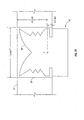
- FIG. 1B illustrates a known light emitting diode (LED) package 30 with a longitudinal package axis 26.
- LED package 30 includes an LED chip 38, a lens 32 with straight vertical sidewall 35 and a funnel-shaped top surface 37.
- the first light path P1 is desirable with the light emitted from chip 38 and traveling to surface 37 where total internal reflection (TIR) causes the light to exit through sidewall 35 at approximately 90 degrees to the longitudinal axis.
- the second light path P2 is light emitted from chip 38 towards sidewall 35 at an angle causing TIR or a reflection from sidewall 35 causing the light to exit package 30 at an angle not close to perpendicular to the longitudinal axis. This path is not desirable and limits the efficiency of side extracted light.
- FIG. 2 illustrates the conventional LED package 10 of FIG. 1 coupled along an edge of a portion of a refractive light guide 20.
- LED package 10 is positioned on the edge of light guide 20 along the width of light guide 20.
- Light rays R1, R2, R3 emitted by LED package 10 are propagated along the length of light guide 20.
- FIG. 3 illustrates a plurality of conventional LED packages 10 positioned along the width of light guide 20 of FIG. 2.
- These conventional LED/light guide combinations are inefficient as they require a large number of LED packages 10 to illuminate the light guide and result in coupling inefficiencies due to relatively small acceptance angles.
- These conventional LED packages 10 must be arranged along the entire length of one side of light guide 20 to fully illuminate light guide 20.
- a lens comprises a bottom surface, a reflecting surface, a first refracting surface obliquely angled with respect to a central axis of the lens, and a second refracting surface extending as a smooth curve from the bottom surface to the first refracting surface.
- Light entering the lens through the bottom surface and directly incident on the reflecting surface is reflected from the reflecting surface to the first refracting surface and refracted by the first refracting surface to exit the lens in a direction substantially perpendicular to the central axis of the lens.
- Light entering the lens through the bottom surface and directly incident on the second refracting surface is refracted by the second refracting surface to exit the lens in a direction substantially perpendicular to the central axis of the lens.
- the inventive lens may be advantageously employed to provide side-emitting light-emitting devices that may be used with light guides and reflectors that have very thin profiles and/or large illuminated areas.
- a light-emitting device comprises a light-emitting semiconductor device and a lens.
- the lens comprises a bottom surface, a reflecting surface, a first refracting surface obliquely angled with respect to a central axis of the lens, and a second refracting surface extending as a smooth curve from the bottom surface to the first refracting surface.
- Light emitted by the semiconductor device, entering the lens through the bottom surface, and directly incident on the reflecting surface is reflected from the reflecting surface to the first refracting surface and refracted by the first refracting surface to exit the lens in a direction substantially perpendicular to the central axis of the lens.
- Light emitted by the semiconductor device, entering the lens through the bottom surface, and directly incident on the second refracting surface is refracted by the second refracting surface to exit the lens in a direction substantially perpendicular to the central axis of the lens.
- the inventive light-emitting device may be efficiently coupled to shallow reflectors and to thin light guides. Secondary optics employed with the inventive light-emitting device may have relatively large illuminated areas.
- a lens cap comprises a bottom surface attachable to a lens, a reflecting surface, a first refracting surface obliquely angled with respect to a central axis of the lens cap, and a second refracting surface extending as a smooth curve from the bottom surface to the first refracting surface.
- Light entering the lens cap through the bottom surface and directly incident on the reflecting surface is reflected from the reflecting surface to the first refracting surface and refracted by the first refracting surface to exit the lens cap in a direction substantially perpendicular to the central axis of the lens.
- the inventive lens cap may provide advantages similar to or the same as those described above.
- FIG. 4 illustrates an example of a side emitting LED package 40 in accordance with one embodiment of the invention.
- LED package 40 includes a longitudinal package axis 43, an LED package base 42 and a lens 44.
- Lens 44 is coupled to LED package base 42.
- Longitudinal package axis 43 passes through the center of LED package base 43 and lens 44.
- a surface of LED package base 42 supports an LED chip 52 (a semiconductor chip having a light emitting pn junction) for generating light.
- LED chip 52 may be one of any number of shapes, including but not limited to a truncated inverted pyramid (TIP) (shown), cube, rectangular solid, or hemisphere.
- TIP truncated inverted pyramid
- LED chip 52 includes a bottom surface that may be in contact with, or coated with, a reflective material. Although LED chip 52 may emit light from all of its sides, base 42 is generally configured to reflect emitted light upwards towards lens 44 along the longitudinal axis of the package. Such bases are conventional and may include a parabolic reflector in which LED chip 52 resides on a surface of package base 42.
- U.S. Patent No. 4,920,404 assigned to the present assignee and incorporated herein by reference.
- Lens 44 may be manufactured as a separate component using a number of well-known techniques such as diamond turning (i.e., the lens is shaped by a lathe with a diamond-bit), injection molding, and casting.
- Lens 44 is made of a transparent material, including but not limited to cyclic olefin copolymer (COC), polymethylmethacrolate (PMMA), polycarbonate (PC), PC/PMMA, silicones, fluorocarbon polymers, and polyetherimide (PEI).
- Lens 44 includes an index of refraction (n) ranging from between about 1.35 to about 1.7, preferably about 1.53, but could have an index of refraction higher or lower based on the material used.
- lens 44 may be formed onto LED package base 42 and LED chip 52 by various techniques including but not limited to injection molding (e.g., insert molding), and casting.
- volume 54 there is a volume 54 between lens 44 and LED chip 52.
- Volume 54 may be filled and sealed to prevent contamination of LED 52 using silicone.
- Volume 54 may also be in a vacuum state, contain air or some other gas, or be filled with an optically transparent material, including but not limited to resin, silicone, epoxy, water or any material with an index of refraction in the range of, for example, about 1.35 to about 1.7 that may be injected to fill volume 54.
- the material inside volume 54 may be colored to act as a filter in order to allow transmission of all or only a portion of the visible light spectrum. If silicone is used, the silicone may be hard or soft.
- Lens 44 may also be colored to act as a filter.
- Lens 44 includes a refractive portion 56 (which may, but does not necessarily, include one or more sawteeth as shown) and a total internal reflection (TIR) funnel portion 58.
- the sawtooth portion 56 is designed to refract and bend light so that the light exits from lens 44 as close to 90 degrees to the longitudinal package axis 43 as possible.
- the sawteeth or refractive surfaces 59 of the sawtooth portion 56 are all light transmissive. Any number of sawteeth 59 may be used within a sawtooth portion of a given length.
- Lens 44 may be formed as a single piece or, in the alternative, as separate components coupled together.
- Funnel portion 58 is designed to have a TIR surface.
- the TIR surface reflects light such that light exits from lens 44 as close to 90 degrees to a longitudinal package axis 43 of LED package 40 as possible. In one implementation, approximately 33% of the light emitted from LED chip 52 is reflected off the TIR surface of funnel-shaped portion 58 of lens 44.
- a metallization layer e.g., aluminum
- a coating or film e.g., a U.V. inhibitor
- the interface between lens 44 and LED package base 42 may also be sealed using any well-known sealant, such as Room Temperature Vulcanizing (RTV) or the like.
- RTV Room Temperature Vulcanizing
- FIG. 5B illustrates a cross-sectional view of alternative mating of lens 44 to housing 46 of LED package base 42.
- LED chip 52 and other features of base 42 are not shown.
- Lens 44 may also be attached to LED package base 42 by various attachment methods, including but not limited to snap-fitting, friction-fitting, heat staking, adhesive bonding, and ultra-sonic welding.
- the features of lens 44, as shown in FIG. 5B, are applicable to lenses that are either formed as a separate component or encapsulated onto LED package base 42.
- FIG. 5C illustrates a close-up of the lens/housing mating of FIG. 5B.
- Surface S may snap fit into surface R.
- Surface S may friction fit tight with surface R.
- Surface T may be welded to surface U using various methods including, without limitation, plastic welding, sonic welding, and linear welding. Sealing or bonding involves several possible combinations, such as surface S and/or T of lens 44 being sealed/bonded to surface R and/or U of housing 46.
- FIG. 5D illustrates a cross-sectional view of a lens cap 55 mating to a conventional LED package 10 with a hemispherical lens 12.
- Lens cap 55 may be affixed to lens 12 of LED package 10 by an optical adhesive, for example.
- Lens cap 55 includes a refractive portion 56 (which may, but does not necessarily, include one or more sawteeth as shown) and reflective funnel portion 58 that may contain the same and/or similar features that operate in the same and/or similar manner, as described above and below, as refractive and TIR portions 56, 58 of lens 44.
- FIGS. 5E, 5F and 5G illustrates ray-traces of light through lenses of various curvatures on the top surface of the lens.
- the features shown in FIGS. 5E-5G are applicable to lenses that are injection molded, cast or otherwise formed.
- approximately 33% of the light emitted from LED chip 52 (not shown; light is shown emitted from die focal point F) is reflected off the TIR surface I.
- FIG. 5E illustrates a curved funnel-shaped portion 58 where Surface I is defined from a curve that maintains an angle greater than the critical angle for TIR but directs the light out of the lens roughly at 90 degrees to longitudinal package axis 53.
- FIG. 5F illustrates a bent-line funnel-shaped portion 58 where Surface I is defined from a line bent into two linear portions, each portion at an angle greater than the critical angle for TIR but directs the light out of the package roughly at 90 degrees to the package axis.
- FIG. 5G illustrates a linear funnel-shaped portion 58 where Surface I is defined by a straight line at an angle greater than the critical angle for TIR but directs the light out of the package roughly at 90 degrees to the package axis.
- FIGS. 5E-5G Surface H works with surface I to emit light perpendicular to longitudinal package axis 53.
- the angle defined by surface I relative to the die is roughly 80 degrees.
- Surfaces A, B, C, D & E have surface normals such that the incident light ray is refracted out of the lens at approximately 90 degrees to the longitudinal package axis 53.
- Surfaces F, G & H are approximately parallel to direct incident light rays in order to minimize the amount of direct light transmitted through these surfaces.
- Surfaces below line N refract light out of the package.
- Surfaces above line M will direct light out of the lens through a combination of TIR and refraction. Lines M & N need to be in close proximity of each other to optimize side emission and minimize emission in the longitudinal direction.
- 5E-5G show two zones: zone refraction at approximately 45 degrees or more from longitudinal package axis 53 and zone TIR/refraction at up to approximately 45 degrees from longitudinal package axis 53.
- zone refraction at approximately 45 degrees or more from longitudinal package axis 53
- zone TIR/refraction at up to approximately 45 degrees from longitudinal package axis 53.
- FIGS. 5E-5G an approximately 40 degree TIR/refraction zone is shown.
- the interface between the two zones is approximately 45 degrees from the longitudinal package axis 53.
- a distance X between Line M and Line N is kept at a minimum in order to optimize the side extraction of light from the lens.
- FIG. 6 illustrates a cross-section of the emission of light from LED package 40 of FIG. 4.
- Lens 44 of LED package 40 creates a radiation pattern 62 roughly perpendicular to longitudinal package axis 66 of LED package 40.
- this radiation pattern 62 is approximately perpendicular to LED package axis 66 and illustrates relative light intensity and distribution.
- This field of illumination 62 surrounds LED package 40 and is roughly disk-or toroidal-shaped.
- Light is emitted from lens 44 approximately parallel to an optical plane 64.
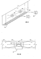
- FIG. 7A illustrates two planar light guides placed nearly end-to-end with space for at least one LED package 40 between light guides 72.
- the side-emission of light from the LED package 40 allows light to enter each light guide 72.
- the LED package 40 may also be inserted into the body of light guide 72.
- Light guides of various shapes may be used.
- the sides along the length of the light guides may be planar or taper.
- a single side emitting LED package 40 may be placed at the center of a disk-shaped light guide (not shown). As light is emitted from the side of LED package 40 over 360 degrees (i.e., in all directions from the center of LED package 40), the light enters the light guide and is refracted and reflected throughout the entire light guide (not shown).
- the light guide can be made from optically transmissive materials, including but not limited to PC or PMMA.
- the light guide may be of constant thickness or tapered. Side emission of light allows efficient illumination of thin light guides with a thickness in the optimum range of 2 to 8 mm.
- FIG. 7B illustrates an example of a light guide 73 with a thickness of 5.0 mm which is greater than the height of lens 44. As the thickness of light guide 73 is greater than the height of the lens 44, a blind-hole 94 may be used in light guide 73 to allow coupling of the LED package 40.
- the dimensions of lenses 44 of FIGS. 7B, 7C & 7D are measured from the focal point F of lens 44.
- FIG. 7C illustrates an example of a light guide 75 with a thickness of 4.5 mm and equal to the height of lens 44.
- a through-hole 96 may be used in light guide 75 to allow coupling of LED package 40.
- FIG. 7D illustrates side-emission of light from the LED of FIG. 4 into a light guide 77 thinner than the height of lens 44.
- a through-hole 96 must be used in the light guide 77 to allow coupling of LED package 40.
- Light guide 77 is thinner than the height of lens 44, a large portion of the light emitted from LED chip 52 will still be directed into light guide 77 as the bulk of the light emitted from LED chip 52 is emitted from the sides of lens 44.
- the large portion of the light emitted from lens 44 is targeted toward a light guide 77 that is positioned midway up the height of the lens. For example, the light emitted out the side of lens 44 near the top will be directed slightly downward and the light emitted out the side of lens 44 near the bottom will be directed slightly upward.
- the portion of light directed into light guide 77 decreases as the thickness of light guide 77 relative to lens 44 decreases.
- Light guide 77 may be any shape including, without limitation, straight, tapered, rectangular, round or square.
- lenses and light guides may have dimensions either larger or smaller than those of the illustrated implementations.
- FIG. 8 illustrates a perspective view of an end-portion of a planar light guide 82.
- the side emitting LED package 40 allows LED package 40 to be placed inside light guide 82.
- One or more holes 86 are made in the body of light guide 82 with a corresponding number of LED assemblies 40 placed within holes 86. Holes 86 may be made to any desired depth in light guide 82, including but not limited to the entire thickness of light guide 82.
- Lens 44 of LED package 40 may not touch light guide 82.
- a reflective coating or film 84 may be placed on at least one of the ends of light guide 82 to increase the internal illumination of light guide 82.
- FIG. 9A illustrates a side-emitting LED package 40 mounted in a blind-hole 94 of a planar light guide 82.
- Top surface 91 of blind-hole 94 is approximately parallel with top surface 95 of planar light guide 82.
- Top surface 91 of blind-hole 94 may be coated with a reflective coating or film to reflect light in order to allow for a thinner light guide package with a similar coupling efficiency.
- FIG. 9B illustrates a side-emitting LED package 40 mounted in a funnel-shaped blind-hole 98 of a planar light guide 82.
- the top surface 93 of funnel-shaped blind-hole 98 is approximately parallel with funnel-shaped portion 58 of lens 44 of LED package 40.
- Top surface 93 of blind-hole 98 may be coated to reflect light in order to allow for a thinner light guide package with a similar coupling efficiency.
- the blind hole can have a flat, funnel or curved surface to assist with redirecting light emitted from the LED into the light guide.
- FIG. 9C illustrates a side-emitting LED package 40 mounted in a v-shaped blind-hole 97 of a planar light guide 82.
- the v-shaped top surface 99 of the blind-hole 97 is approximately parallel with funnel-shaped portion 58 of lens 44 of LED package 40.
- the blind hole can have a flat, funnel or curved surface to assist with redirecting light emitted from the LED into the light guide.
- the top surface 99 of blind-hole 97 may be coated to reflect light in order to allow for a thinner light guide package with a similar coupling efficiency.
- FIG. 10 illustrates a side-emitting LED package 40 mounted in a through-hole 96 of a planar light guide 82.
- Through-hole 96 allows LED package 40 to be mounted approximately perpendicular with light guide 82.
- FIG. 11 illustrates a conventional LED/reflector arrangement. It is known to use an LED package 10 with a hemispherical lens 12 in combination with a deep reflector 92. The deep shape of the cavity of reflector 92 collimates light emitted from the hemispherical lens 12 of LED package 10. This deep reflector cavity is required to control the light.
- a shallow, large-area reflector 102 can be used in combination with a side-emitting LED package 40 to emit light over a broader area than a conventional LED package 10.
- the longitudinal package axis 116 of the lens is approximately parallel to a radial axis 122 of reflector 102.
- the side-emission of light allows the walls of reflector 102 to be less deep than conventional reflectors 92 (FIG. 11).
- Light is emitted from lens 144 roughly perpendicular to longitudinal package axis 116 of LED package 40.
- Side-emitting LED package 40 allows for very high collection efficiencies with shallow large area reflectors compared to conventional LEDs.
- Shallow reflectors 102 collimate emitted light over a broader area than narrow, deep reflectors 92 used in combination with conventional LED assemblies 10.
- Shallow, large-area reflector 102 may be made of BMC bulk molding compound, PC, PMMA, PC/PMMA, and PEI.
- a reflective film 120 covering the inside of reflector 102 could be metallized, sputtered, or the like with highly reflective materials including, for example, aluminum (Al) and nickel chrome (NiCr). Side-emitting LEDs can achieve higher collection efficiencies with deep or shallow reflectors than the conventional LED/deep reflector combination.
- a light-emitting device 150 includes a lens 152 similar to but differing from lens 44 disclosed above.
- lens 152 includes a funnel shaped portion 58 having a reflecting (e.g., totally internally reflecting) surface I and a refracting surface H, but does not include a refractive sawtooth portion such as sawtooth portion 56 of lens 44 (FIG. 5A).
- lower portion 154 of lens 152 has a refracting surface 156 extending as a smooth curve from refracting surface H to a bottom surface 158 of lens 152.
- bottom surface 158 of lens 152 may be considered to include the interface between volume 54 and the other portions of lens 152.
- volume 54 includes a non-gaseous material such as a solid, liquid, or gel, then bottom surface 158 may be considered to include the interface of such material with LED package base 42 and with LED 52.
- lens 152 may be symmetrical (e.g., cylindrically symmetrical) about a central axis 43.
- Reflecting surface I of lens 152 may have shapes such as, for example, those described above and depicted in FIGS. 5E-5G for surface I of lens 44.
- Lens 152 may be formed from any of the materials and fabricated by any of the methods described above as suitable for fabrication of lens 44.
- light emitted by a light-emitting semiconductor device such as LED 52 located approximately at the focal point F of lens 152 may enter lens 152 through bottom surface 158 of the lens.
- Light emitted from near focal point F that is directly incident on reflecting surface I is reflected from surface I to refracting surface H and refracted by surface H to exit lens 152 in a direction substantially perpendicular to the central axis 43 of the lens.
- Light emitted from near focal point F that is directly incident on refracting surface 156 is refracted by surface 156 to also exit lens 152 in a direction substantially perpendicular to axis 43.
- the light rays illustrated in FIG. 13 and in the other figures are not shown as refracted at the interface of volume 54 with the other portions of lens 152. Generally, refraction of such light rays at this interface will occur due to a (typically small) difference in the refractive index between the material in volume 54 and the material of the other portions of the lens.
- the shapes of surfaces I, H, and 156 are typically chosen to take such refraction into account.
- FIG. 15 illustrates a cross-sectional view of lens 152 superimposed over a cross-sectional view of a lens 160 (dashed line) that includes a single refractive sawtooth.
- lens 160 is substantially similar in structure and function to lens 44 disclosed above.
- the implementations of lens 152 and 160 shown in FIG. 15 are optimized for use with substantially similar LEDs in substantially similar packages. Hence, the lowermost portions of lens 152 and lens 160 are substantially identical in size and shape.
- the diameter D1 of the funnel shaped portion 58 of lens 152 is substantially less than the diameter D2 of its lower portion 154.
- the diameter of the funnel shaped portion of lens 160 is approximately equal to the diameter of its lowermost portion.
- the relatively smaller diameter of the funnel shaped portion 58 of lens 152 makes lens 152 easier and less expensive than lens 160 (or other lenses including refractive sawteeth) to manufacture, to insert into and to attach to an LED package, and to fill with, for example, silicone or resin.
- Light-emitting device 150 may be employed with, for example, light guides and shallow, large-area reflectors similarly as disclosed above for other LED packages and light-emitting devices.
- a lens cap 162 mates to a conventional LED package 10 having a hemispherical lens 12.
- Lens cap 162 may be attached to lens 12 by an optical adhesive, for example.
- Lens cap 162 includes a funnel shaped portion 58 having a reflecting (e.g., totally internally reflecting) surface I and a refracting surface H, as well as a lower portion 154 having a refracting surface 156 extending as a smooth curve from refracting surface H to a bottom surface 158.
- Lens cap 162 may have the shapes and symmetries disclosed above for lens 152, and may be formed from any of the materials and by any of the methods described above as suitable for fabrication of lenses 44 and 152.
- light emitted by LED package 10 is directed by surfaces I, H, and 156 of lens cap 162 in a direction substantially perpendicular to a central axis 43 of the lens cap.
Applications Claiming Priority (2)
| Application Number | Priority Date | Filing Date | Title |
|---|---|---|---|
| US179600 | 2002-06-24 | ||
| US10/179,600 US6679621B2 (en) | 2002-06-24 | 2002-06-24 | Side emitting LED and lens |
Publications (3)
| Publication Number | Publication Date |
|---|---|
| EP1376708A2 true EP1376708A2 (de) | 2004-01-02 |
| EP1376708A3 EP1376708A3 (de) | 2010-05-19 |
| EP1376708B1 EP1376708B1 (de) | 2011-11-30 |
Family
ID=29717908
Family Applications (1)
| Application Number | Title | Priority Date | Filing Date |
|---|---|---|---|
| EP03076985A Expired - Lifetime EP1376708B1 (de) | 2002-06-24 | 2003-06-23 | Seitlich emittierende Leuchtdiode und Linse |
Country Status (5)
| Country | Link |
|---|---|
| US (1) | US6679621B2 (de) |
| EP (1) | EP1376708B1 (de) |
| JP (1) | JP4623944B2 (de) |
| AT (1) | ATE535945T1 (de) |
| TW (1) | TWI331811B (de) |
Cited By (37)
| Publication number | Priority date | Publication date | Assignee | Title |
|---|---|---|---|---|
| EP1617135A3 (de) * | 2004-07-16 | 2006-02-22 | Osram-Sylvania Inc. | Leuchtdiode mit einem eingegossenen Reflektor |
| WO2006089523A1 (de) * | 2005-02-28 | 2006-08-31 | Osram Opto Semiconductors Gmbh | Beleuchtungsvorrichtung |
| EP1701204A1 (de) * | 2005-03-08 | 2006-09-13 | Sony Corporation | Rückbeleuchtungsvorrichtung und Flüssigkristallanzeige |
| EP1717627A1 (de) * | 2005-04-26 | 2006-11-02 | LG Electronics, Inc. | Optische Linse, Gehäuse einer lichtemittierenden Vorrichtung mit der optischen Linse und Hintergrundbeleuchtungseinheit |
| FR2886237A1 (fr) * | 2005-05-27 | 2006-12-01 | Valeo Vision Sa | Dispositif d'eclairage ou de signalisation d'aspect ameliore pour vehicule automobile |
| NL1031225C2 (nl) * | 2005-02-26 | 2006-12-12 | Samsung Electronics Co Ltd | Lineaire zij-uitzender, tegenlichtsysteem en vloeibaar kristal beeldscherm gebruik makend van hetzelfde. |
| EP1737051A1 (de) * | 2005-06-24 | 2006-12-27 | L.G. Philips LCD Co., Ltd. | Rückbeleuchtungsanordnung mit lichtemittierender Diode und Anzeigevorrichtung damit |
| EP1768197A2 (de) * | 2005-09-27 | 2007-03-28 | LG Electronics Inc. | Leuchtdioden-Verpackung und Rückbeleuchtungseinheit |
| WO2007036186A1 (de) * | 2005-09-30 | 2007-04-05 | Osram Opto Semiconductors Gmbh | Beleuchtungsanordnung |
| WO2007041574A1 (en) * | 2005-10-03 | 2007-04-12 | S. C. Johnson & Son, Inc. | Light apparatus |
| WO2007057819A1 (en) * | 2005-11-21 | 2007-05-24 | Koninklijke Philips Electronics N.V. | Lighting device |
| NL1031502C2 (nl) * | 2005-04-04 | 2007-05-30 | Samsung Electronics Co Ltd | Achterverlichtingseenheid en vloeibaar kristaldisplay dat daarvan gebruik maakt. |
| WO2007065698A1 (de) | 2005-12-06 | 2007-06-14 | Arnold & Richter Cine Technik Gmbh & Co. Betriebs Kg | Flächenleuchte |
| WO2007099275A1 (en) | 2006-02-28 | 2007-09-07 | Ghollam Tahmosybayat | Lens assembly |
| FR2901753A1 (fr) * | 2006-06-02 | 2007-12-07 | Valeo Vision Sa | Dispositif d'eclairage interieur multifonctions pour vehicule automobile |
| GB2447558A (en) * | 2007-03-12 | 2008-09-17 | Nicotech Ltd | Light emitting beacon |
| WO2008146290A2 (en) * | 2007-05-29 | 2008-12-04 | Oree, Advanced Illumination Solutions Inc. | Method and device for providing circumferential illumination |
| WO2008152610A2 (en) * | 2007-06-14 | 2008-12-18 | Koninklijke Philips Electronics N.V. | Thin flash or video recording light using low profile side emitting led |
| US7570846B2 (en) | 2004-06-21 | 2009-08-04 | Oree, Advanced Illumination Solutions Inc. | High efficacy waveguide coupler |
| WO2009040722A3 (en) * | 2007-09-27 | 2009-08-13 | Koninkl Philips Electronics Nv | Thin backlight using low profile side emitting leds |
| WO2009149010A1 (en) | 2008-06-04 | 2009-12-10 | 3M Innovative Properties Company | Hollow backlight with tilted light source |
| WO2010076103A2 (de) * | 2008-12-08 | 2010-07-08 | Osram Opto Semiconductors Gmbh | Beleuchtungseinrichtung |
| US7826698B1 (en) | 2007-12-19 | 2010-11-02 | Oree, Inc. | Elimination of stitch artifacts in a planar illumination area |
| EP1624498A3 (de) * | 2004-08-03 | 2011-03-30 | Philips Lumileds Lighting Company LLC | Verpackung für ein Licht emittierendes Halbleiterbauelement |
| US7929816B2 (en) | 2007-12-19 | 2011-04-19 | Oree, Inc. | Waveguide sheet containing in-coupling, propagation, and out-coupling regions |
| US8337044B2 (en) | 2007-10-25 | 2012-12-25 | Koninklijke Philips Electronics N.V. | Elongated luminaire comprising LEDs for illuminating objects in front of the luminaire |
| EP2541288A1 (de) * | 2011-06-27 | 2013-01-02 | Kun Dian Photoelectric Enterprise Co. | Lichtleiter-LED-Vorrichtung zur indirekten Beleuchtung |
| CN103307549A (zh) * | 2012-03-14 | 2013-09-18 | 三星电子株式会社 | 透镜以及采用该透镜的球型发光器件灯 |
| US8684585B2 (en) | 2010-08-31 | 2014-04-01 | Wintek (China) Technology Ltd. | Illumination device and lens thereof |
| US9010951B2 (en) | 2013-07-05 | 2015-04-21 | Lg Innotek Co., Ltd. | Optical lens, light emitting device, and display |
| US9164218B2 (en) | 2008-07-10 | 2015-10-20 | Oree, Inc. | Slim waveguide coupling apparatus and method |
| US9404638B2 (en) | 2011-03-25 | 2016-08-02 | Nalux Co., Ltd. | Optical element and illumination unit |
| EP2132479B1 (de) * | 2007-04-02 | 2016-09-07 | Cree, Inc. | Lichtlenkendes led-gerät |
| US9857519B2 (en) | 2012-07-03 | 2018-01-02 | Oree Advanced Illumination Solutions Ltd. | Planar remote phosphor illumination apparatus |
| EP2191521B1 (de) * | 2007-08-16 | 2018-10-10 | Lumileds Holding B.V. | An eine niedrigprofil-seitenemissions-led gekoppeltes optisches element |
| WO2019081802A1 (en) * | 2017-10-23 | 2019-05-02 | Ledil Oy | PRINTED CIRCUIT BOARD, ITS PRODUCTION METHOD, AND ILLUMINATION DEVICE COMPRISING THE SAME |
| EP3832199A1 (de) * | 2019-12-06 | 2021-06-09 | Marelli Automotive Lighting Italy S.p.A. | Kfz-beleuchtungs- und / oder signalvorrichtung und zugehörige montageverfahren |
Families Citing this family (392)
| Publication number | Priority date | Publication date | Assignee | Title |
|---|---|---|---|---|
| KR101201307B1 (ko) * | 2005-06-30 | 2012-11-14 | 엘지디스플레이 주식회사 | 백라이트유닛 |
| US6896381B2 (en) * | 2002-10-11 | 2005-05-24 | Light Prescriptions Innovators, Llc | Compact folded-optics illumination lens |
| US7042655B2 (en) * | 2002-12-02 | 2006-05-09 | Light Prescriptions Innovators, Llc | Apparatus and method for use in fulfilling illumination prescription |
| US7377671B2 (en) * | 2003-02-04 | 2008-05-27 | Light Prescriptions Innovators, Llc | Etendue-squeezing illumination optics |
| US7320531B2 (en) * | 2003-03-28 | 2008-01-22 | Philips Lumileds Lighting Company, Llc | Multi-colored LED array with improved brightness profile and color uniformity |
| TWI282022B (en) * | 2003-03-31 | 2007-06-01 | Sharp Kk | Surface lighting device and liquid crystal display device using the same |
| US8075147B2 (en) * | 2003-05-13 | 2011-12-13 | Light Prescriptions Innovators, Llc | Optical device for LED-based lamp |
| US7021797B2 (en) * | 2003-05-13 | 2006-04-04 | Light Prescriptions Innovators, Llc | Optical device for repositioning and redistributing an LED's light |
| US7329029B2 (en) | 2003-05-13 | 2008-02-12 | Light Prescriptions Innovators, Llc | Optical device for LED-based lamp |
| EP1660918B1 (de) * | 2003-07-29 | 2017-03-15 | Light Engine Limited | Umfänglich emittierende leuchtvorrichtungen und durch transversalachsen-profil-sweeps gebildete linsenelemente |
| DE10343529A1 (de) * | 2003-09-19 | 2005-04-21 | Pepperl & Fuchs | Vorrichtung zur optischen Übermittlung von Information |
| MY130919A (en) * | 2003-09-19 | 2007-07-31 | Mattel Inc | Multidirectional light emitting diode unit |
| US7314296B2 (en) * | 2003-12-08 | 2008-01-01 | Honeywell International Inc. | Multi-platform aircraft forward position light utilizing LED-based light source |
| US7434970B2 (en) * | 2004-03-12 | 2008-10-14 | Honeywell International Inc. | Multi-platform LED-based aircraft rear position light |
| US7182496B2 (en) | 2004-04-14 | 2007-02-27 | Opto Technology, Inc. | Multiple LED focused lighting device |
| JP4305850B2 (ja) * | 2004-05-24 | 2009-07-29 | 株式会社 日立ディスプレイズ | バックライト装置及び表示装置 |
| CN1956668B (zh) * | 2004-05-26 | 2012-02-29 | 吉尔科有限公司 | 用于产品陈列柜的led照明系统 |
| KR100586965B1 (ko) * | 2004-05-27 | 2006-06-08 | 삼성전기주식회사 | 발광 다이오드 소자 |
| KR100586966B1 (ko) * | 2004-05-27 | 2006-06-08 | 삼성전기주식회사 | 수직 발광형 백라이트 모듈 |
| KR100586970B1 (ko) * | 2004-05-28 | 2006-06-08 | 삼성전기주식회사 | 액정 디스플레이 표시장치의 백라이트 유닛 |
| KR100586968B1 (ko) * | 2004-05-28 | 2006-06-08 | 삼성전기주식회사 | Led 패키지 및 이를 구비한 액정표시장치용 백라이트어셈블리 |
| US7520650B2 (en) * | 2004-06-28 | 2009-04-21 | Whelen Engineering Company, Inc. | Side-emitting collimator |
| US7083313B2 (en) * | 2004-06-28 | 2006-08-01 | Whelen Engineering Company, Inc. | Side-emitting collimator |
| US7118262B2 (en) * | 2004-07-23 | 2006-10-10 | Cree, Inc. | Reflective optical elements for semiconductor light emitting devices |
| KR101136587B1 (ko) * | 2004-07-27 | 2012-04-18 | 돌비 레버러토리즈 라이쎈싱 코오포레이션 | 광원 어레이로부터의 광을 위한 확산기 및 그와 일체화되는디스플레이 |
| KR20060012959A (ko) * | 2004-08-05 | 2006-02-09 | 삼성전자주식회사 | 표시 장치용 백라이트 |
| WO2006020535A2 (en) * | 2004-08-09 | 2006-02-23 | Valeo Sylvania Llc | Led bulb refractive relector |
| KR100616598B1 (ko) * | 2004-08-11 | 2006-08-28 | 삼성전기주식회사 | 발광 다이오드 렌즈 및 이를 구비한 백라이트 모듈 |
| US7217022B2 (en) * | 2004-08-31 | 2007-05-15 | Opto Technology, Inc. | Optic fiber LED light source |
| CN101014894B (zh) * | 2004-09-08 | 2010-11-10 | 奥斯兰姆奥普托半导体有限责任公司 | 侧面发出辐射的器件和用于如此器件的透镜 |
| DE102004043516A1 (de) * | 2004-09-08 | 2006-03-23 | Osram Opto Semiconductors Gmbh | Seitlich emittierendes strahlungserzeugendes Bauelement und Linse für ein solches Bauelement |
| US7410275B2 (en) * | 2004-09-21 | 2008-08-12 | Lumination Llc | Refractive optic for uniform illumination |
| DE102005045589A1 (de) | 2004-09-24 | 2006-04-06 | Epistar Corp. | Flüssigkristalldisplay |
| TWI249257B (en) * | 2004-09-24 | 2006-02-11 | Epistar Corp | Illumination apparatus |
| KR100677135B1 (ko) * | 2004-09-25 | 2007-02-02 | 삼성전자주식회사 | 측 발광 디바이스 및 이를 광원으로 사용하는 백라이트유닛 및 이를 채용한 액정표시장치 |
| CN100433385C (zh) * | 2004-09-30 | 2008-11-12 | 晶元光电股份有限公司 | 发光装置 |
| US7748873B2 (en) * | 2004-10-07 | 2010-07-06 | Seoul Semiconductor Co., Ltd. | Side illumination lens and luminescent device using the same |
| CN100416378C (zh) * | 2004-10-08 | 2008-09-03 | 索尼株式会社 | 背照光用光源单元、液晶显示用背照光装置及透射型液晶显示装置 |
| US8541795B2 (en) * | 2004-10-12 | 2013-09-24 | Cree, Inc. | Side-emitting optical coupling device |
| KR100688767B1 (ko) * | 2004-10-15 | 2007-02-28 | 삼성전기주식회사 | Led 광원용 렌즈 |
| KR101080355B1 (ko) | 2004-10-18 | 2011-11-04 | 삼성전자주식회사 | 발광다이오드와 그 렌즈 |
| KR100638657B1 (ko) * | 2004-10-20 | 2006-10-30 | 삼성전기주식회사 | 양극성 측면 방출형 발광 다이오드 렌즈 및 이를 구비하는발광 다이오드 모듈 |
| US7901102B2 (en) * | 2004-10-22 | 2011-03-08 | Samsung Electronics Co., Ltd. | Backlight unit and liquid crystal display apparatus employing the same |
| KR100657281B1 (ko) * | 2004-10-29 | 2006-12-14 | 삼성전자주식회사 | 측 발광 디바이스 및 이를 광원으로 사용하는 백라이트유닛 및 이를 채용한 액정표시장치 |
| KR100657284B1 (ko) * | 2004-11-03 | 2006-12-14 | 삼성전자주식회사 | 백라이트 유닛 및 이를 채용한 액정표시장치 |
| US7352011B2 (en) * | 2004-11-15 | 2008-04-01 | Philips Lumileds Lighting Company, Llc | Wide emitting lens for LED useful for backlighting |
| US7344902B2 (en) * | 2004-11-15 | 2008-03-18 | Philips Lumileds Lighting Company, Llc | Overmolded lens over LED die |
| KR100580753B1 (ko) | 2004-12-17 | 2006-05-15 | 엘지이노텍 주식회사 | 발광소자 패키지 |
| TWI261654B (en) * | 2004-12-29 | 2006-09-11 | Ind Tech Res Inst | Lens and LED with uniform light emitted applying the lens |
| CN100371792C (zh) * | 2004-12-30 | 2008-02-27 | 联准实业有限公司 | 直下式背光模块 |
| TWI314233B (en) * | 2004-12-30 | 2009-09-01 | Ind Tech Res Inst | A backlight module using diffraction optical element |
| TWI313775B (en) * | 2005-01-06 | 2009-08-21 | Au Optronics Corp | Backlight module and illumination device thereof |
| TWI266079B (en) * | 2005-01-10 | 2006-11-11 | Shiu-Hua Huang | Steering lens and light emitting system using the same |
| TWI246606B (en) * | 2005-01-12 | 2006-01-01 | Au Optronics Corp | Backlight module, dish lens for backlight module and light emitting diode |
| DE102006002275A1 (de) * | 2005-01-19 | 2006-07-20 | Osram Opto Semiconductors Gmbh | Beleuchtungseinrichtung |
| DE102005061431B4 (de) * | 2005-02-03 | 2020-01-02 | Samsung Electronics Co., Ltd. | LED-Einheit der Art Seitenausstrahlung |
| KR100649640B1 (ko) * | 2005-02-03 | 2006-11-27 | 삼성전기주식회사 | 측면 방출형 발광다이오드 패키지 |
| CN100359381C (zh) * | 2005-02-08 | 2008-01-02 | 友达光电股份有限公司 | 背光组件的碟形透镜与点状光源 |
| CN100350313C (zh) * | 2005-02-08 | 2007-11-21 | 友达光电股份有限公司 | 液晶显示器的背光组件 |
| US20060187650A1 (en) * | 2005-02-24 | 2006-08-24 | 3M Innovative Properties Company | Direct lit backlight with light recycling and source polarizers |
| US7275849B2 (en) * | 2005-02-25 | 2007-10-02 | Visteon Global Technologies, Inc. | LED replacement bulb |
| KR101134301B1 (ko) * | 2005-02-28 | 2012-04-13 | 엘지디스플레이 주식회사 | 엘이디 백라이트어셈블리 및 이를 이용한 액정표시장치모듈 |
| US7413689B2 (en) * | 2005-03-24 | 2008-08-19 | Syntec Technologies Inc. | Lens element from diamond-turned thermoplastic resin |
| TWI262604B (en) * | 2005-04-19 | 2006-09-21 | Young Lighting Technology Inc | LED lens |
| US7942560B2 (en) * | 2005-04-28 | 2011-05-17 | Cooper Technologies Company | Apparatus and method of using an LED light source to generate an efficient, narrow, high-aspect ratio light pattern |
| KR101044682B1 (ko) * | 2005-05-06 | 2011-06-28 | 에피스타 코포레이션 | 조명 패키지 |
| CN1866552A (zh) * | 2005-05-18 | 2006-11-22 | 光宝科技股份有限公司 | 光线行进方向改变单元及含有其的模块和发光二极管组件 |
| CN100430801C (zh) * | 2005-05-27 | 2008-11-05 | 友达光电股份有限公司 | 背光模块及其照明装置 |
| JP4458359B2 (ja) * | 2005-06-06 | 2010-04-28 | スタンレー電気株式会社 | レンズおよびレンズユニット並びにそれらを具備する灯具 |
| WO2006131924A2 (en) | 2005-06-07 | 2006-12-14 | Oree, Advanced Illumination Solutions Inc. | Illumination apparatus |
| US8272758B2 (en) | 2005-06-07 | 2012-09-25 | Oree, Inc. | Illumination apparatus and methods of forming the same |
| US8215815B2 (en) | 2005-06-07 | 2012-07-10 | Oree, Inc. | Illumination apparatus and methods of forming the same |
| US20060285311A1 (en) * | 2005-06-19 | 2006-12-21 | Chih-Li Chang | Light-emitting device, backlight module, and liquid crystal display using the same |
| KR100705704B1 (ko) * | 2005-06-21 | 2007-04-09 | 주식회사 나모텍 | 엘이디 어레이용 렌즈 및 이를 이용한 백라이트 장치 |
| KR100784057B1 (ko) | 2005-06-24 | 2007-12-10 | 엘지이노텍 주식회사 | 발광소자 패키지 및 발광소자 패키지 제조 방법 |
| US7339196B2 (en) * | 2005-06-25 | 2008-03-04 | Industrial Technology Research Institute | Packaging of SMD light emitting diodes |
| US20060291203A1 (en) * | 2005-06-27 | 2006-12-28 | Munisamy Anandan | Fiber mixed R-G-B white emitting LED package |
| KR100631992B1 (ko) * | 2005-07-19 | 2006-10-09 | 삼성전기주식회사 | 측면 방출형 이중 렌즈 구조 led 패키지 |
| US20070018182A1 (en) * | 2005-07-20 | 2007-01-25 | Goldeneye, Inc. | Light emitting diodes with improved light extraction and reflectivity |
| CN100378488C (zh) * | 2005-07-21 | 2008-04-02 | 香港理工大学 | 侧面发射发光二极管光源的内透镜 |
| KR20070013469A (ko) * | 2005-07-26 | 2007-01-31 | 삼성전자주식회사 | 광학렌즈 및 광학 패키지와, 이를 갖는 백라이트 어셈블리및 표시장치 |
| JP2009503793A (ja) * | 2005-07-28 | 2009-01-29 | ライト プレスクリプションズ イノベーターズ エルエルシー | バックライトおよびフロントライト用のエテンデュ保存型照明光学部品 |
| US8631787B2 (en) * | 2005-07-28 | 2014-01-21 | Light Prescriptions Innovators, Llc | Multi-junction solar cells with a homogenizer system and coupled non-imaging light concentrator |
| WO2007016363A2 (en) * | 2005-07-28 | 2007-02-08 | Light Prescriptions Innovators, Llc | Free-form lenticular optical elements and their application to condensers and headlamps |
| KR100757196B1 (ko) * | 2005-08-01 | 2007-09-07 | 서울반도체 주식회사 | 실리콘 렌즈를 구비하는 발광소자 |
| TWI260380B (en) * | 2005-08-05 | 2006-08-21 | Chi Lin Technology Co Ltd | Lens for LED |
| JP2007048775A (ja) * | 2005-08-05 | 2007-02-22 | Koito Mfg Co Ltd | 発光ダイオードおよび車両用灯具 |
| KR100651550B1 (ko) * | 2005-08-18 | 2006-11-29 | 삼성전기주식회사 | 상, 중, 하부로 구성된 led 광원용 렌즈 |
| TW200717131A (en) * | 2005-08-19 | 2007-05-01 | Lg Chemical Ltd | Side emitting lens, light emitting device using the side emitting lens, mold assembly for preparing the side emitting lens and method for preparing the side emitting lens |
| US7311420B2 (en) * | 2005-08-22 | 2007-12-25 | Avago Technologies Ecbuip Pte Ltd | Opto-electronic package, and methods and systems for making and using same |
| KR100722590B1 (ko) * | 2005-08-30 | 2007-05-28 | 삼성전기주식회사 | 백라이트용 led 렌즈 |
| US20070047932A1 (en) * | 2005-08-31 | 2007-03-01 | Branson Ultrasonics Corporation | Waveguide for plastics welding using an incoherent infrared light source |
| TWI323373B (en) * | 2005-09-06 | 2010-04-11 | Ind Tech Res Inst | Structure of bar-like side emitting light guide and planar light source module |
| CN100399149C (zh) * | 2005-09-19 | 2008-07-02 | 中强光电股份有限公司 | 发光装置与面光源模块 |
| US7339202B2 (en) * | 2005-09-21 | 2008-03-04 | Chunghwa Picture Tubes, Ltd. | Backlight module and a light-emitting-diode package structure therefor |
| US7293908B2 (en) * | 2005-10-18 | 2007-11-13 | Goldeneye, Inc. | Side emitting illumination systems incorporating light emitting diodes |
| US7378686B2 (en) * | 2005-10-18 | 2008-05-27 | Goldeneye, Inc. | Light emitting diode and side emitting lens |
| WO2007046059A1 (en) * | 2005-10-21 | 2007-04-26 | Philips Intellectual Property & Standards Gmbh | A light device |
| WO2007050483A2 (en) * | 2005-10-24 | 2007-05-03 | 3M Innovative Properties Company | Method of making light emitting device having a molded encapsulant |
| US7595515B2 (en) | 2005-10-24 | 2009-09-29 | 3M Innovative Properties Company | Method of making light emitting device having a molded encapsulant |
| US7943946B2 (en) * | 2005-11-21 | 2011-05-17 | Sharp Kabushiki Kaisha | Light emitting device |
| KR100742726B1 (ko) * | 2005-11-22 | 2007-07-25 | 주식회사 나모텍 | 백라이트 유닛 |
| JP4600257B2 (ja) * | 2005-11-25 | 2010-12-15 | ソニー株式会社 | 導光板、バックライト装置とその製造方法及び液晶表示装置 |
| US7306351B2 (en) * | 2005-12-14 | 2007-12-11 | Chung Yuan Christian University | Lens for side emitting LED device |
| EP1960709A4 (de) * | 2005-12-14 | 2009-01-14 | Legrand Australia Pty Ltd | Lichtquelle |
| RU2303800C1 (ru) * | 2005-12-15 | 2007-07-27 | Самсунг Электроникс Ко., Лтд. | Линза для формирования излучения светодиода |
| DE102006033893B4 (de) * | 2005-12-16 | 2017-02-23 | Osram Opto Semiconductors Gmbh | Beleuchtungseinrichtung |
| US7375379B2 (en) * | 2005-12-19 | 2008-05-20 | Philips Limileds Lighting Company, Llc | Light-emitting device |
| TWI333572B (en) * | 2005-12-20 | 2010-11-21 | Ind Tech Res Inst | Light source package structure |
| US7637639B2 (en) * | 2005-12-21 | 2009-12-29 | 3M Innovative Properties Company | LED emitter with radial prismatic light diverter |
| US20070200118A1 (en) * | 2005-12-21 | 2007-08-30 | Epstein Kenneth A | Led light confinement element |
| JP4729720B2 (ja) | 2005-12-21 | 2011-07-20 | 株式会社 日立ディスプレイズ | 面状照明装置及びこの面状照明装置をバックライトとした液晶表示装置 |
| CN101346583B (zh) | 2005-12-27 | 2011-11-23 | 昭和电工株式会社 | 光导部件、平坦光源装置和显示装置 |
| CN101625085B (zh) * | 2005-12-31 | 2011-10-12 | 财团法人工业技术研究院 | 光源封装结构 |
| JP2009530798A (ja) | 2006-01-05 | 2009-08-27 | イルミテックス, インコーポレイテッド | Ledから光を導くための独立した光学デバイス |
| TWI322312B (en) * | 2006-01-19 | 2010-03-21 | Au Optronics Corp | Backlight module and light spread device |
| CN100403128C (zh) * | 2006-02-08 | 2008-07-16 | 友达光电股份有限公司 | 背光模块及光扩散组件 |
| TWI281556B (en) * | 2006-03-15 | 2007-05-21 | Bright Led Electronics Corp | Lens, light-emitting apparatus with lens and its manufacturing method |
| CN100456505C (zh) * | 2006-04-10 | 2009-01-28 | 中强光电股份有限公司 | 发光模块 |
| US20070257271A1 (en) * | 2006-05-02 | 2007-11-08 | 3M Innovative Properties Company | Led package with encapsulated converging optical element |
| US7953293B2 (en) * | 2006-05-02 | 2011-05-31 | Ati Technologies Ulc | Field sequence detector, method and video device |
| US20070258241A1 (en) * | 2006-05-02 | 2007-11-08 | 3M Innovative Properties Company | Led package with non-bonded converging optical element |
| US7390117B2 (en) * | 2006-05-02 | 2008-06-24 | 3M Innovative Properties Company | LED package with compound converging optical element |
| US20070257270A1 (en) * | 2006-05-02 | 2007-11-08 | 3M Innovative Properties Company | Led package with wedge-shaped optical element |
| US7525126B2 (en) | 2006-05-02 | 2009-04-28 | 3M Innovative Properties Company | LED package with converging optical element |
| US20070269586A1 (en) * | 2006-05-17 | 2007-11-22 | 3M Innovative Properties Company | Method of making light emitting device with silicon-containing composition |
| TWI287117B (en) * | 2006-05-25 | 2007-09-21 | Ind Tech Res Inst | Light guide lens and light emitting diode package structure having the light guide lens |
| US20070284589A1 (en) * | 2006-06-08 | 2007-12-13 | Keat Chuan Ng | Light emitting device having increased light output |
| TWI319629B (en) * | 2006-06-27 | 2010-01-11 | Au Optronics Corp | Light emitting diode module |
| US20080012001A1 (en) * | 2006-07-12 | 2008-01-17 | Evident Technologies | Shaped articles comprising semiconductor nanocrystals and methods of making and using same |
| WO2008008994A2 (en) * | 2006-07-14 | 2008-01-17 | Light Prescriptions Innovators, Llc | Brightness-enhancing film |
| US7438445B2 (en) * | 2006-07-14 | 2008-10-21 | Coretronic Corporation | Side-emitting light-emitting element and packaging lens thereof |
| US7254309B1 (en) | 2006-07-14 | 2007-08-07 | Coretronic Corporation | Side emitting LED and lens |
| WO2008011377A2 (en) * | 2006-07-17 | 2008-01-24 | 3M Innovative Properties Company | Led package with converging extractor |
| DE102006034070A1 (de) * | 2006-07-20 | 2008-01-31 | Schefenacker Vision Systems Germany Gmbh | Leuchteinheit mit einer Leuchtdiode mit integriertem Lichtumlenkkörper |
| WO2008022064A2 (en) * | 2006-08-10 | 2008-02-21 | Light Prescriptions Innovators, Llc | Led light recycling device |
| WO2008022065A2 (en) * | 2006-08-11 | 2008-02-21 | Light Prescriptions Innovators, Llc | Led luminance-enhancement and color-mixing by rotationally multiplexed beam-combining |
| US8092735B2 (en) * | 2006-08-17 | 2012-01-10 | 3M Innovative Properties Company | Method of making a light emitting device having a molded encapsulant |
| US7800122B2 (en) * | 2006-09-07 | 2010-09-21 | Hong Kong Applied Science And Technology Research Institute Co., Ltd. | Light emitting diode device, and manufacture and use thereof |
| CN101145593A (zh) * | 2006-09-14 | 2008-03-19 | 鸿富锦精密工业(深圳)有限公司 | 发光二极管及其制备方法 |
| CN101150160A (zh) * | 2006-09-22 | 2008-03-26 | 鸿富锦精密工业(深圳)有限公司 | 发光二极管及其制备方法 |
| CN101150159B (zh) * | 2006-09-22 | 2011-05-11 | 鸿富锦精密工业(深圳)有限公司 | 发光二极管及其透镜体 |
| US20090275266A1 (en) * | 2006-10-02 | 2009-11-05 | Illumitex, Inc. | Optical device polishing |
| CN101553928B (zh) * | 2006-10-02 | 2011-06-01 | 伊鲁米特克有限公司 | Led系统和方法 |
| US7524098B2 (en) * | 2006-10-12 | 2009-04-28 | Dicon Fiberoptics, Inc. | Solid-state lateral emitting optical system |
| US7847306B2 (en) * | 2006-10-23 | 2010-12-07 | Hong Kong Applied Science and Technology Research Insitute Company, Ltd. | Light emitting diode device, method of fabrication and use thereof |
| US20080101062A1 (en) * | 2006-10-27 | 2008-05-01 | Hong Kong Applied Science and Technology Research Institute Company Limited | Lighting device for projecting a beam of light |
| KR101221066B1 (ko) | 2006-10-30 | 2013-02-12 | 삼성전자주식회사 | 측면 방출 렌즈와 이를 구비한 백라이트 유닛 및액정표시장치 |
| KR20090089431A (ko) * | 2006-11-17 | 2009-08-21 | 쓰리엠 이노베이티브 프로퍼티즈 컴파니 | Led 광원용 광학 접합 조성물 |
| WO2008064068A2 (en) * | 2006-11-17 | 2008-05-29 | 3M Innovative Properties Company | Planarized led with optical extractor |
| CN101548398A (zh) * | 2006-11-20 | 2009-09-30 | 3M创新有限公司 | 用于led光源的光学粘合组合物 |
| JP4561732B2 (ja) * | 2006-11-20 | 2010-10-13 | トヨタ自動車株式会社 | 移動体位置測位装置 |
| CN101206271B (zh) * | 2006-12-19 | 2012-04-11 | 香港应用科技研究院有限公司 | 全反射侧发射耦合装置 |
| US20090067175A1 (en) * | 2007-01-04 | 2009-03-12 | Bright Led Electronics Corp. | Lens for use with a light-emitting element and light source device including the lens |
| CN101226974B (zh) * | 2007-01-18 | 2011-01-05 | 财团法人工业技术研究院 | 具有微镜体结构的发光二极管芯片 |
| ITGE20070073A1 (it) * | 2007-07-31 | 2009-02-01 | Giorgio Gai | Elemento radiante per pannelli luminosi e pannello luminoso realizzato con detto elemento radiante |
| US9944031B2 (en) * | 2007-02-13 | 2018-04-17 | 3M Innovative Properties Company | Molded optical articles and methods of making same |
| KR20090115803A (ko) | 2007-02-13 | 2009-11-06 | 쓰리엠 이노베이티브 프로퍼티즈 컴파니 | 렌즈를 갖는 led 소자 및 그 제조 방법 |
| KR100883075B1 (ko) | 2007-03-02 | 2009-02-10 | 엘지전자 주식회사 | 전계발광소자 |
| ES2353936T3 (es) * | 2007-04-05 | 2011-03-08 | Koninklijke Philips Electronics N.V. | Conformador de haz luminoso. |
| CN101290373A (zh) * | 2007-04-18 | 2008-10-22 | 鸿富锦精密工业(深圳)有限公司 | 背光模组及其光学板 |
| US8770801B1 (en) | 2007-05-01 | 2014-07-08 | Musco Corporation | Apparatus and method for pathway or similar lighting |
| US7976199B2 (en) * | 2007-05-01 | 2011-07-12 | Musco Corporation | Apparatus and method for pathway or similar lighting |
| TWI439641B (zh) | 2007-05-20 | 2014-06-01 | 3M Innovative Properties Co | 用於側面發光型背光之準直光注入器 |
| CN101681056B (zh) | 2007-05-20 | 2013-03-27 | 3M创新有限公司 | 中空光循环腔型显示器背光源 |
| TWI458918B (zh) | 2007-05-20 | 2014-11-01 | 3M Innovative Properties Co | 具有有利設計特性之薄形中空背光 |
| EP2500767A1 (de) | 2007-05-20 | 2012-09-19 | 3M Innovative Properties Company | Halbspiegelnde Komponente in Rückbeleuchtungen, welche einen dünnen Hohlraum aufweisen und das Licht mehrfach verwenden |
| GB0712614D0 (en) * | 2007-06-29 | 2007-08-08 | Dialight Lumidrives Ltd | Improved spatial luminance |
| US8791631B2 (en) | 2007-07-19 | 2014-07-29 | Quarkstar Llc | Light emitting device |
| CN101373223B (zh) * | 2007-08-20 | 2012-09-26 | 香港应用科技研究院有限公司 | 光学元件及包含其之背光模块 |
| TWI354839B (en) * | 2007-08-28 | 2011-12-21 | Chunghwa Picture Tubes Ltd | Back light module |
| US7967477B2 (en) * | 2007-09-06 | 2011-06-28 | Philips Lumileds Lighting Company Llc | Compact optical system and lenses for producing uniform collimated light |
| US8506132B2 (en) * | 2007-10-04 | 2013-08-13 | Dragonfish Technologies Llc | Method and apparatus for creating high efficiency radial circular lighting distributions from a hemispherical lambertian source |
| US7703950B2 (en) * | 2007-11-21 | 2010-04-27 | C-R Control Systems, Inc. | Side-emitting lens for LED lamp |
| JP5261684B2 (ja) * | 2007-11-27 | 2013-08-14 | スタンレー電気株式会社 | ストロボ装置 |
| TWI386685B (zh) * | 2007-12-14 | 2013-02-21 | Chimei Innolux Corp | 光學元件、背光模組及顯示裝置 |
| US8118447B2 (en) | 2007-12-20 | 2012-02-21 | Altair Engineering, Inc. | LED lighting apparatus with swivel connection |
| US7712918B2 (en) | 2007-12-21 | 2010-05-11 | Altair Engineering , Inc. | Light distribution using a light emitting diode assembly |
| CN101499507B (zh) * | 2008-02-01 | 2011-11-09 | 富准精密工业(深圳)有限公司 | 发光二极管 |
| WO2009100307A1 (en) | 2008-02-07 | 2009-08-13 | 3M Innovative Properties Company | Hollow backlight with structured films |
| CN101939849A (zh) * | 2008-02-08 | 2011-01-05 | 伊鲁米特克有限公司 | 用于发射器层成形的系统和方法 |
| EP2090820A3 (de) * | 2008-02-15 | 2010-08-25 | Opto Technology Inc. | Hochintensives auf abgestuften LEDs basiertes Licht |
| CN101952646B (zh) | 2008-02-22 | 2014-01-29 | 3M创新有限公司 | 具有选定的输出光通量分布的背光源及使用该背光源的显示系统 |
| EP2260341A2 (de) | 2008-03-05 | 2010-12-15 | Oree, Advanced Illumination Solutions INC. | Beleuchtungsvorrichtung und verfahren zu ihrer bildung |
| US9557033B2 (en) * | 2008-03-05 | 2017-01-31 | Cree, Inc. | Optical system for batwing distribution |
| CN101539266B (zh) * | 2008-03-19 | 2011-05-11 | 富准精密工业(深圳)有限公司 | 发光元件及其透镜 |
| CN101562221A (zh) * | 2008-04-18 | 2009-10-21 | 富准精密工业(深圳)有限公司 | 侧面发光二极管 |
| KR20100137524A (ko) * | 2008-04-23 | 2010-12-30 | 에이전시 포 사이언스, 테크놀로지 앤드 리서치 | 발광 다이오드 구조, 램프 장치 및 발광 다이오드 구조를 형성하는 방법 |
| US8449144B2 (en) | 2008-05-16 | 2013-05-28 | Musco Corporation | Apparatus, method, and system for highly controlled light distribution using multiple light sources |
| US8356916B2 (en) * | 2008-05-16 | 2013-01-22 | Musco Corporation | Method, system and apparatus for highly controlled light distribution from light fixture using multiple light sources (LEDS) |
| US8388193B2 (en) * | 2008-05-23 | 2013-03-05 | Ruud Lighting, Inc. | Lens with TIR for off-axial light distribution |
| US9423096B2 (en) | 2008-05-23 | 2016-08-23 | Cree, Inc. | LED lighting apparatus |
| US8348475B2 (en) | 2008-05-23 | 2013-01-08 | Ruud Lighting, Inc. | Lens with controlled backlight management |
| US8360599B2 (en) | 2008-05-23 | 2013-01-29 | Ilumisys, Inc. | Electric shock resistant L.E.D. based light |
| US7781832B2 (en) * | 2008-05-28 | 2010-08-24 | Ptek Technology Co., Ltd. | Trench-type power MOS transistor and integrated circuit utilizing the same |
| KR100990640B1 (ko) | 2008-05-29 | 2010-10-29 | 삼성엘이디 주식회사 | 확산렌즈 및 확산렌즈를 이용한 발광소자 조립체 |
| TWI381134B (zh) * | 2008-06-02 | 2013-01-01 | 榮創能源科技股份有限公司 | 發光二極體光源模組 |
| US7766509B1 (en) | 2008-06-13 | 2010-08-03 | Lumec Inc. | Orientable lens for an LED fixture |
| US8002435B2 (en) * | 2008-06-13 | 2011-08-23 | Philips Electronics Ltd Philips Electronique Ltee | Orientable lens for an LED fixture |
| CN101615642A (zh) * | 2008-06-25 | 2009-12-30 | 富准精密工业(深圳)有限公司 | 发光二极管 |
| US20090322800A1 (en) | 2008-06-25 | 2009-12-31 | Dolby Laboratories Licensing Corporation | Method and apparatus in various embodiments for hdr implementation in display devices |
| US7976196B2 (en) | 2008-07-09 | 2011-07-12 | Altair Engineering, Inc. | Method of forming LED-based light and resulting LED-based light |
| US8301002B2 (en) | 2008-07-10 | 2012-10-30 | Oree, Inc. | Slim waveguide coupling apparatus and method |
| JP5176750B2 (ja) * | 2008-07-24 | 2013-04-03 | ソニー株式会社 | 発光素子組立体、面状光源装置、及び、液晶表示装置組立体 |
| US7946729B2 (en) | 2008-07-31 | 2011-05-24 | Altair Engineering, Inc. | Fluorescent tube replacement having longitudinally oriented LEDs |
| US7841750B2 (en) | 2008-08-01 | 2010-11-30 | Ruud Lighting, Inc. | Light-directing lensing member with improved angled light distribution |
| US8674626B2 (en) | 2008-09-02 | 2014-03-18 | Ilumisys, Inc. | LED lamp failure alerting system |
| US8256924B2 (en) | 2008-09-15 | 2012-09-04 | Ilumisys, Inc. | LED-based light having rapidly oscillating LEDs |
| JP5220533B2 (ja) * | 2008-09-29 | 2013-06-26 | 株式会社朝日ラバー | レンズ及びそれを用いた光学製品 |
| US8226262B2 (en) * | 2008-09-30 | 2012-07-24 | Reflexite Corporation | TIRing condensing element and methods thereof |
| US20100091507A1 (en) * | 2008-10-03 | 2010-04-15 | Opto Technology, Inc. | Directed LED Light With Reflector |
| US7980727B2 (en) | 2008-10-07 | 2011-07-19 | Reflexite Corporation | Monolithic tiring condensing arrays and methods thereof |
| US8214084B2 (en) | 2008-10-24 | 2012-07-03 | Ilumisys, Inc. | Integration of LED lighting with building controls |
| US8653984B2 (en) | 2008-10-24 | 2014-02-18 | Ilumisys, Inc. | Integration of LED lighting control with emergency notification systems |
| US8901823B2 (en) | 2008-10-24 | 2014-12-02 | Ilumisys, Inc. | Light and light sensor |
| US7938562B2 (en) | 2008-10-24 | 2011-05-10 | Altair Engineering, Inc. | Lighting including integral communication apparatus |
| US8324817B2 (en) | 2008-10-24 | 2012-12-04 | Ilumisys, Inc. | Light and light sensor |
| US8444292B2 (en) | 2008-10-24 | 2013-05-21 | Ilumisys, Inc. | End cap substitute for LED-based tube replacement light |
| US8662716B2 (en) * | 2008-11-18 | 2014-03-04 | Orafol Americas Inc. | Side-emitting optical elements and methods thereof |
| TW201034256A (en) * | 2008-12-11 | 2010-09-16 | Illumitex Inc | Systems and methods for packaging light-emitting diode devices |
| US8317352B2 (en) * | 2008-12-11 | 2012-11-27 | Robert Saccomanno | Non-invasive injection of light into a transparent substrate, such as a window pane through its face |
| JP5118617B2 (ja) * | 2008-12-22 | 2013-01-16 | パナソニック株式会社 | 照明用レンズ、発光装置、面光源および液晶ディスプレイ装置 |
| US8556452B2 (en) | 2009-01-15 | 2013-10-15 | Ilumisys, Inc. | LED lens |
| US8362710B2 (en) | 2009-01-21 | 2013-01-29 | Ilumisys, Inc. | Direct AC-to-DC converter for passive component minimization and universal operation of LED arrays |
| US8664880B2 (en) | 2009-01-21 | 2014-03-04 | Ilumisys, Inc. | Ballast/line detection circuit for fluorescent replacement lamps |
| US8246212B2 (en) * | 2009-01-30 | 2012-08-21 | Koninklijke Philips Electronics N.V. | LED optical assembly |
| TW201030281A (en) | 2009-02-13 | 2010-08-16 | Ama Precision Inc | Light-emitting apparatus and light-guiding member thereof |
| US8576406B1 (en) | 2009-02-25 | 2013-11-05 | Physical Optics Corporation | Luminaire illumination system and method |
| JP5257609B2 (ja) * | 2009-03-04 | 2013-08-07 | スタンレー電気株式会社 | 光学モジュール及び照明用灯具 |
| US8624527B1 (en) | 2009-03-27 | 2014-01-07 | Oree, Inc. | Independently controllable illumination device |
| US8425076B2 (en) | 2009-03-31 | 2013-04-23 | Carmanah Technologies Corp. | Solar powered airfield light |
| US8616733B1 (en) | 2009-04-22 | 2013-12-31 | Tomar Electronics, Inc. | Light emitting diode optical system and related methods |
| US10422503B2 (en) | 2009-10-30 | 2019-09-24 | Ideal Industries Lighting Llc | One-piece multi-lens optical member and method of manufacture |
| US9915409B2 (en) | 2015-02-19 | 2018-03-13 | Cree, Inc. | Lens with textured surface facilitating light diffusion |
| US10119662B2 (en) | 2009-04-28 | 2018-11-06 | Cree, Inc. | Lens with controlled light refraction |
| US9416926B2 (en) | 2009-04-28 | 2016-08-16 | Cree, Inc. | Lens with inner-cavity surface shaped for controlled light refraction |
| US9217854B2 (en) * | 2009-04-28 | 2015-12-22 | Cree, Inc. | Lens with controlled light refraction |
| US8328406B2 (en) | 2009-05-13 | 2012-12-11 | Oree, Inc. | Low-profile illumination device |
| US8330381B2 (en) * | 2009-05-14 | 2012-12-11 | Ilumisys, Inc. | Electronic circuit for DC conversion of fluorescent lighting ballast |
| US8047675B1 (en) | 2009-05-19 | 2011-11-01 | Tomar Electronics, Inc. | Light emitting diode optical system and related methods |
| US9255686B2 (en) | 2009-05-29 | 2016-02-09 | Cree, Inc. | Multi-lens LED-array optic system |
| US8299695B2 (en) * | 2009-06-02 | 2012-10-30 | Ilumisys, Inc. | Screw-in LED bulb comprising a base having outwardly projecting nodes |
| US8531115B2 (en) * | 2009-06-18 | 2013-09-10 | Musco Corporation | Apparatus and method for bypassing failed LEDs in lighting arrays |
| US8421366B2 (en) | 2009-06-23 | 2013-04-16 | Ilumisys, Inc. | Illumination device including LEDs and a switching power control system |
| WO2010150202A2 (en) | 2009-06-24 | 2010-12-29 | Oree, Advanced Illumination Solutions Inc. | Illumination apparatus with high conversion efficiency and methods of forming the same |
| TWI395021B (zh) * | 2009-07-02 | 2013-05-01 | Hannstar Display Corp | 液晶顯示器之背光模組 |
| US8622569B1 (en) | 2009-07-17 | 2014-01-07 | Musco Corporation | Method, system and apparatus for controlling light distribution using swivel-mount led light sources |
| US20110038141A1 (en) * | 2009-08-11 | 2011-02-17 | Martin David Tillin | Lateral emission led backlight for lcd |
| US8662704B2 (en) * | 2009-08-14 | 2014-03-04 | U.S. Pole Company, Inc. | LED optical system with multiple levels of secondary optics |
| US8585253B2 (en) | 2009-08-20 | 2013-11-19 | Illumitex, Inc. | System and method for color mixing lens array |
| US8449128B2 (en) * | 2009-08-20 | 2013-05-28 | Illumitex, Inc. | System and method for a lens and phosphor layer |
| US20110051413A1 (en) * | 2009-08-25 | 2011-03-03 | Abl Ip Holding Llc | Optic shielding |
| US8382337B2 (en) * | 2009-09-18 | 2013-02-26 | Luxingtek, Ltd. | Lighting device, light spreading plate and method for manufacturing the same |
| WO2011055467A1 (ja) * | 2009-11-04 | 2011-05-12 | ナルックス株式会社 | 照明装置 |
| US8434914B2 (en) * | 2009-12-11 | 2013-05-07 | Osram Sylvania Inc. | Lens generating a batwing-shaped beam distribution, and method therefor |
| US8330342B2 (en) * | 2009-12-21 | 2012-12-11 | Malek Bhairi | Spherical light output LED lens and heat sink stem system |
| JP5626754B2 (ja) * | 2010-01-10 | 2014-11-19 | シチズン電子株式会社 | 光学ユニット |
| TWI418854B (zh) * | 2010-03-16 | 2013-12-11 | Cal Comp Electronics & Comm Co | 透鏡結構 |
| CA2794512A1 (en) | 2010-03-26 | 2011-09-29 | David L. Simon | Led light tube with dual sided light distribution |
| US8651695B2 (en) * | 2010-03-26 | 2014-02-18 | Excelitas Technologies Corp. | LED based high-intensity light with secondary diffuser |
| WO2011119921A2 (en) * | 2010-03-26 | 2011-09-29 | Altair Engineering, Inc. | Led light with thermoelectric generator |
| EP2553332B1 (de) | 2010-03-26 | 2016-03-23 | iLumisys, Inc. | Umgestülpte led-glühlampe |
| US9068707B1 (en) | 2010-04-06 | 2015-06-30 | Musco Corporation | Compact LED light source and lighting system |
| KR101064036B1 (ko) * | 2010-06-01 | 2011-09-08 | 엘지이노텍 주식회사 | 발광 소자 패키지 및 조명 시스템 |
| JP2012009696A (ja) * | 2010-06-25 | 2012-01-12 | Panasonic Electric Works Co Ltd | 発光装置およびそれを用いたled照明器具 |
| US8454193B2 (en) | 2010-07-08 | 2013-06-04 | Ilumisys, Inc. | Independent modules for LED fluorescent light tube replacement |
| JP2013531350A (ja) | 2010-07-12 | 2013-08-01 | イルミシス,インコーポレイテッド | Led発光管用回路基板取付台 |
| US20110140148A1 (en) | 2010-07-15 | 2011-06-16 | Pinecone Energies, Inc. | Optical device for semiconductor based lamp |
| KR101441008B1 (ko) * | 2010-09-20 | 2014-09-17 | 한국전자통신연구원 | 온도제어가 가능한 광 송신 장치 |
| US8814391B2 (en) | 2010-09-20 | 2014-08-26 | Luxingtek, Ltd. | Light guiding structure |
| US9075172B2 (en) | 2010-09-20 | 2015-07-07 | Luxingtek, Ltd. | Light converting optical structure and lighting device utilizing the same |
| WO2012044824A2 (en) | 2010-09-30 | 2012-04-05 | Musco Corporation | Apparatus, method, and system for led fixture temperature measurement, control, and calibration |
| US20120092887A1 (en) * | 2010-10-15 | 2012-04-19 | Shenzhen China Star Optoelectronics Technology Co., Ltd. | Backlight module and display apparatus |
| EP2633227B1 (de) | 2010-10-29 | 2018-08-29 | iLumisys, Inc. | Mechanismen zur minimierung des risikos von elektroschocks während der installation einer lichtröhre |
| JP5569807B2 (ja) | 2010-11-04 | 2014-08-13 | スタンレー電気株式会社 | 灯具 |
| CN102486292A (zh) * | 2010-12-02 | 2012-06-06 | 西安中科麦特电子技术设备有限公司 | 一种新型led准直光学元件 |
| CN102486293A (zh) * | 2010-12-02 | 2012-06-06 | 西安中科麦特电子技术设备有限公司 | 一种新型led照明光学透镜 |
| US8297799B2 (en) | 2010-12-02 | 2012-10-30 | Aether Systems Inc. | Omnidirectional LED lamp and complex, unitary lens |
| US8870415B2 (en) | 2010-12-09 | 2014-10-28 | Ilumisys, Inc. | LED fluorescent tube replacement light with reduced shock hazard |
| JP5154637B2 (ja) * | 2010-12-21 | 2013-02-27 | 株式会社小糸製作所 | 車両用灯具 |
| JP2011071137A (ja) * | 2010-12-21 | 2011-04-07 | Koito Mfg Co Ltd | 車両用灯具 |
| JP5641332B2 (ja) | 2011-01-24 | 2014-12-17 | スタンレー電気株式会社 | 灯具 |
| JP5643670B2 (ja) * | 2011-02-03 | 2014-12-17 | 株式会社エンプラス | 光束制御部材および照明装置 |
| JP2012178332A (ja) * | 2011-02-04 | 2012-09-13 | Canon Inc | 表示装置 |
| US8684575B2 (en) | 2011-02-24 | 2014-04-01 | Stanley Electric Co., Ltd. | Lighting unit |
| JP2012216764A (ja) * | 2011-03-25 | 2012-11-08 | Sharp Corp | 発光装置、照明装置、および表示装置 |
| DE102011007214B4 (de) * | 2011-04-12 | 2013-08-14 | Osram Gmbh | Kolben für Halbleiter - Leuchtvorrichtung sowie Halbleiter - Leuchtvorrichtung |
| CN102809122A (zh) * | 2011-06-02 | 2012-12-05 | 玉景科技有限公司 | 分光组件及其发光装置 |
| US8876325B2 (en) * | 2011-07-01 | 2014-11-04 | Cree, Inc. | Reverse total internal reflection features in linear profile for lighting applications |
| US8757845B2 (en) * | 2011-07-29 | 2014-06-24 | TSMC Solid State Lighting, Ltd. | Wide angle based indoor lighting lamp |
| US9072171B2 (en) | 2011-08-24 | 2015-06-30 | Ilumisys, Inc. | Circuit board mount for LED light |
| US8523407B2 (en) | 2011-09-13 | 2013-09-03 | Chun Kuang Optics Corp. | Optical element and illuminant device using the same |
| KR101449091B1 (ko) * | 2011-11-10 | 2014-10-08 | 엘지이노텍 주식회사 | 광속 제어 부재 및 이를 포함하는 표시장치 |
| US8591072B2 (en) | 2011-11-16 | 2013-11-26 | Oree, Inc. | Illumination apparatus confining light by total internal reflection and methods of forming the same |
| CN104115290B (zh) | 2011-11-23 | 2017-04-05 | 夸克星有限责任公司 | 提供光的不对称传播的发光装置 |
| US9541257B2 (en) | 2012-02-29 | 2017-01-10 | Cree, Inc. | Lens for primarily-elongate light distribution |
| US9541258B2 (en) | 2012-02-29 | 2017-01-10 | Cree, Inc. | Lens for wide lateral-angle distribution |
| US10408429B2 (en) | 2012-02-29 | 2019-09-10 | Ideal Industries Lighting Llc | Lens for preferential-side distribution |
| WO2013131002A1 (en) | 2012-03-02 | 2013-09-06 | Ilumisys, Inc. | Electrical connector header for an led-based light |
| KR101359972B1 (ko) | 2012-04-20 | 2014-02-12 | 주식회사 포스코 | 초광각 고균제도 엘이디렌즈 |
| US8979347B2 (en) * | 2012-04-24 | 2015-03-17 | Qualcomm Mems Technologies, Inc. | Illumination systems and methods |
| US9223080B2 (en) | 2012-04-24 | 2015-12-29 | Qualcomm Mems Technologies, Inc. | Light guide with narrow angle light output and methods |
| CN107293631B (zh) * | 2012-04-28 | 2019-02-01 | 上海浦壹电子科技有限公司 | 发光二极管 |
| USD697664S1 (en) | 2012-05-07 | 2014-01-14 | Cree, Inc. | LED lens |
| JP5538479B2 (ja) * | 2012-06-19 | 2014-07-02 | 三菱電機株式会社 | Led光源及びそれを用いた発光体 |
| CN103511911B (zh) * | 2012-06-26 | 2016-08-24 | 扬升照明股份有限公司 | 光源模块 |
| US9163794B2 (en) | 2012-07-06 | 2015-10-20 | Ilumisys, Inc. | Power supply assembly for LED-based light tube |
| US9271367B2 (en) | 2012-07-09 | 2016-02-23 | Ilumisys, Inc. | System and method for controlling operation of an LED-based light |
| US8992052B2 (en) * | 2012-08-03 | 2015-03-31 | GE Lighting Solutions, LLC | Inner lens optics for omnidirectional lamp |
| JP5988764B2 (ja) * | 2012-08-10 | 2016-09-07 | 株式会社小糸製作所 | 車両用照明灯具 |
| EP2895793B1 (de) | 2012-09-13 | 2020-11-04 | Quarkstar LLC | Lichtemittierende vorrichtungen mit reflektierenden elementen |
| EP2896079B1 (de) | 2012-09-13 | 2018-02-28 | Quarkstar LLC | Lichtemittierende vorrichtung mit einem fernstreuungselement und einem extraktorelement mt totalreflexion |
| KR20140040558A (ko) * | 2012-09-26 | 2014-04-03 | 엘지이노텍 주식회사 | 광속 제어 부재, 이를 포함하는 발광 장치 및 표시장치 |
| CN104718467B (zh) * | 2012-10-19 | 2017-07-14 | 飞利浦灯具控股公司 | 具有棱镜元件的用于间接光照的照明设备 |
| KR101299528B1 (ko) * | 2012-12-18 | 2013-08-23 | (주)애니캐스팅 | 측면 방출형 발광다이오드용 렌즈, 이를 구비하는 백라이트유닛 및 표시장치 |
| TWI565972B (zh) * | 2012-12-24 | 2017-01-11 | 鴻海精密工業股份有限公司 | 光學透鏡以及應用該光學透鏡的發光元件 |
| CN103883985A (zh) * | 2012-12-24 | 2014-06-25 | 鸿富锦精密工业(深圳)有限公司 | 光学透镜以及应用该光学透镜的发光元件 |
| US9291320B2 (en) | 2013-01-30 | 2016-03-22 | Cree, Inc. | Consolidated troffer |
| US9690029B2 (en) | 2013-01-30 | 2017-06-27 | Cree, Inc. | Optical waveguides and luminaires incorporating same |
| US9366396B2 (en) | 2013-01-30 | 2016-06-14 | Cree, Inc. | Optical waveguide and lamp including same |
| US9869432B2 (en) | 2013-01-30 | 2018-01-16 | Cree, Inc. | Luminaires using waveguide bodies and optical elements |
| US10234616B2 (en) | 2013-01-30 | 2019-03-19 | Cree, Inc. | Simplified low profile module with light guide for pendant, surface mount, wall mount and stand alone luminaires |
| US9625638B2 (en) | 2013-03-15 | 2017-04-18 | Cree, Inc. | Optical waveguide body |
| US9411086B2 (en) | 2013-01-30 | 2016-08-09 | Cree, Inc. | Optical waveguide assembly and light engine including same |
| US9519095B2 (en) | 2013-01-30 | 2016-12-13 | Cree, Inc. | Optical waveguides |
| US9442243B2 (en) | 2013-01-30 | 2016-09-13 | Cree, Inc. | Waveguide bodies including redirection features and methods of producing same |
| US9752757B2 (en) | 2013-03-07 | 2017-09-05 | Quarkstar Llc | Light-emitting device with light guide for two way illumination |
| US9683710B2 (en) | 2013-03-07 | 2017-06-20 | Quarkstar Llc | Illumination device with multi-color light-emitting elements |
| US9285084B2 (en) | 2013-03-14 | 2016-03-15 | Ilumisys, Inc. | Diffusers for LED-based lights |
| US10379278B2 (en) * | 2013-03-15 | 2019-08-13 | Ideal Industries Lighting Llc | Outdoor and/or enclosed structure LED luminaire outdoor and/or enclosed structure LED luminaire having outward illumination |
| US9920901B2 (en) | 2013-03-15 | 2018-03-20 | Cree, Inc. | LED lensing arrangement |
| WO2014151688A1 (en) * | 2013-03-15 | 2014-09-25 | Cree, Inc. | Lens with controlled light refraction |
| US10436970B2 (en) | 2013-03-15 | 2019-10-08 | Ideal Industries Lighting Llc | Shaped optical waveguide bodies |
| US10209429B2 (en) | 2013-03-15 | 2019-02-19 | Cree, Inc. | Luminaire with selectable luminous intensity pattern |
| WO2014144706A2 (en) * | 2013-03-15 | 2014-09-18 | Quarkstar Llc | Color tuning of light-emitting devices |
| US9366799B2 (en) | 2013-03-15 | 2016-06-14 | Cree, Inc. | Optical waveguide bodies and luminaires utilizing same |
| USD718490S1 (en) | 2013-03-15 | 2014-11-25 | Cree, Inc. | LED lens |
| US9798072B2 (en) | 2013-03-15 | 2017-10-24 | Cree, Inc. | Optical element and method of forming an optical element |
| US10502899B2 (en) * | 2013-03-15 | 2019-12-10 | Ideal Industries Lighting Llc | Outdoor and/or enclosed structure LED luminaire |
| US10400984B2 (en) | 2013-03-15 | 2019-09-03 | Cree, Inc. | LED light fixture and unitary optic member therefor |
| KR101524914B1 (ko) | 2013-03-28 | 2015-06-01 | 엘지이노텍 주식회사 | 광확산 소자, 및 이를 갖는 발광소자 어레이 유닛 |
| KR101304279B1 (ko) * | 2013-04-08 | 2013-09-11 | (주)애니캐스팅 | 측면 방출형 발광다이오드용 렌즈 |
| KR20140123134A (ko) * | 2013-04-10 | 2014-10-22 | 삼성전자주식회사 | 반사형 확산 렌즈 및 조명장치 |
| USD752779S1 (en) | 2013-05-07 | 2016-03-29 | Osram Sylvania Inc. | Light guide for an LED lamp |
| US9133988B2 (en) | 2013-05-07 | 2015-09-15 | Osram Sylvania Inc. | LED-based lamp including shaped light guide |
| JP6207236B2 (ja) * | 2013-05-28 | 2017-10-04 | 三菱電機株式会社 | 点光源、面状光源装置および表示装置 |
| DE102013212353B4 (de) * | 2013-06-26 | 2023-02-02 | Automotive Lighting Reutlingen Gmbh | Kraftfahrzeugbeleuchtungseinrichtung mit einer eine Einkoppeloptik und eine Transport- und Umformoptik aufweisenden Lichtleiteranordnung |
| CN104421832A (zh) * | 2013-08-21 | 2015-03-18 | 展晶科技(深圳)有限公司 | 透镜及具有该透镜的发光元件 |
| US9267650B2 (en) | 2013-10-09 | 2016-02-23 | Ilumisys, Inc. | Lens for an LED-based light |
| US8979320B1 (en) * | 2013-10-23 | 2015-03-17 | Kevin McDermott | LED lighting device |
| NL2012030C2 (en) * | 2013-12-27 | 2015-06-30 | Orga B V | Beacon light optic, beacon light. |
| WO2015099533A1 (en) * | 2013-12-27 | 2015-07-02 | Orga Holding B.V. | Beacon light optic, beacon light |
| US9523479B2 (en) | 2014-01-03 | 2016-12-20 | Cree, Inc. | LED lens |
| KR20160111975A (ko) | 2014-01-22 | 2016-09-27 | 일루미시스, 인크. | 어드레스된 led들을 갖는 led 기반 조명 |
| US10030847B2 (en) | 2014-03-10 | 2018-07-24 | Streamlight, Inc. | Portable light and optical diffuser therefor |
| US9510400B2 (en) | 2014-05-13 | 2016-11-29 | Ilumisys, Inc. | User input systems for an LED-based light |
| US9568768B2 (en) | 2014-06-28 | 2017-02-14 | Radiant Choice Limited | Wavelength mixing optical component |
| US9488864B2 (en) | 2014-06-28 | 2016-11-08 | Radiant Choice Limited | Light distributing optical component |
| DE102014213380A1 (de) | 2014-07-09 | 2016-01-14 | Osram Gmbh | Beleuchtungsvorrichtung mit optoelektronischer Lichtquelle |
| US9757912B2 (en) | 2014-08-27 | 2017-09-12 | Cree, Inc. | One-piece multi-lens optical member with ultraviolet inhibitor and method of manufacture |
| US10207440B2 (en) | 2014-10-07 | 2019-02-19 | Cree, Inc. | Apparatus and method for formation of multi-region articles |
| US9470394B2 (en) | 2014-11-24 | 2016-10-18 | Cree, Inc. | LED light fixture including optical member with in-situ-formed gasket and method of manufacture |
| KR102300558B1 (ko) * | 2014-12-26 | 2021-09-14 | 삼성전자주식회사 | 광원 모듈 |
| US11306897B2 (en) | 2015-02-09 | 2022-04-19 | Ecosense Lighting Inc. | Lighting systems generating partially-collimated light emissions |
| US9869450B2 (en) | 2015-02-09 | 2018-01-16 | Ecosense Lighting Inc. | Lighting systems having a truncated parabolic- or hyperbolic-conical light reflector, or a total internal reflection lens; and having another light reflector |
| US10801696B2 (en) | 2015-02-09 | 2020-10-13 | Ecosense Lighting Inc. | Lighting systems generating partially-collimated light emissions |
| WO2016137026A1 (ko) * | 2015-02-25 | 2016-09-01 | 에이테크솔루션(주) | 미세광학패턴이 형성된 하이브리드 타입의 엘이디 렌즈 |
| KR102239628B1 (ko) | 2015-04-03 | 2021-04-12 | 엘지이노텍 주식회사 | 렌즈 및 이를 포함하는 발광소자 모듈 |
| CN104777549A (zh) * | 2015-04-23 | 2015-07-15 | 福州大学 | 液晶显示器用导光条 |
| KR102325585B1 (ko) * | 2015-05-28 | 2021-11-12 | 엘지이노텍 주식회사 | 조명장치 및 이를 포함하는 차량램프 |
| US10161568B2 (en) | 2015-06-01 | 2018-12-25 | Ilumisys, Inc. | LED-based light with canted outer walls |
| CN106291896B (zh) * | 2015-06-05 | 2019-12-20 | 瑞仪光电(苏州)有限公司 | 光学透镜、背光模块 |
| KR102471271B1 (ko) | 2015-06-05 | 2022-11-29 | 삼성전자주식회사 | 광학 소자 및 이를 포함하는 광원 모듈 |
| KR20170025396A (ko) | 2015-08-28 | 2017-03-08 | 삼성전자주식회사 | 반사형 확산 렌즈 및 이를 포함하는 조명 장치 |
| US9638392B2 (en) | 2015-09-25 | 2017-05-02 | Osram Sylvania Inc. | Lamp optic for use in LED-based lamp |
| TWI589190B (zh) * | 2016-03-07 | 2017-06-21 | 禪才高科技股份有限公司 | 容易更換x射線管的x射線離子產生器 |
| US10416377B2 (en) | 2016-05-06 | 2019-09-17 | Cree, Inc. | Luminaire with controllable light emission |
| US11719882B2 (en) | 2016-05-06 | 2023-08-08 | Ideal Industries Lighting Llc | Waveguide-based light sources with dynamic beam shaping |
| CN106322243B (zh) * | 2016-10-13 | 2019-06-18 | 惠科股份有限公司 | 显示装置和背光模组 |
| FR3064531B1 (fr) * | 2017-03-31 | 2019-04-05 | Saint-Gobain Glass France | Vitrage eclairant. |
| US10468566B2 (en) | 2017-04-10 | 2019-11-05 | Ideal Industries Lighting Llc | Hybrid lens for controlled light distribution |
| CN107329318B (zh) * | 2017-05-22 | 2020-09-22 | 海信视像科技股份有限公司 | 一种背光模组及液晶显示装置 |
| US10330902B1 (en) * | 2017-06-16 | 2019-06-25 | Dbm Reflex Enterprises Inc. | Illumination optics and devices |
| CN108198844A (zh) * | 2018-01-03 | 2018-06-22 | 京东方科技集团股份有限公司 | 一种显示面板、其制作方法及显示装置 |
| CN108490685B (zh) * | 2018-03-20 | 2020-11-27 | 惠州市华星光电技术有限公司 | 背光模组和显示装置 |
| JP7225598B2 (ja) * | 2018-08-08 | 2023-02-21 | 船井電機株式会社 | 表示装置 |
| CN111638612A (zh) * | 2019-03-01 | 2020-09-08 | 苏州璨宇光学有限公司 | 光源模块及其制造方法 |
| WO2021022145A1 (en) | 2019-08-01 | 2021-02-04 | Sirius Signal, LLC | Visual distress signal device |
| KR102069381B1 (ko) | 2019-11-09 | 2020-01-22 | 주식회사 레다즈 | 측면 방출형 엘이디 렌즈 |
| USD956602S1 (en) | 2020-03-10 | 2022-07-05 | Sirius Signal, LLC | Visual distress signal device |
| CN112180638A (zh) * | 2020-09-14 | 2021-01-05 | 东莞市谷麦光学科技有限公司 | 一种具有微结构的光学透镜及其应用 |
| US11587362B2 (en) | 2020-12-16 | 2023-02-21 | Lenovo (Singapore) Pte. Ltd. | Techniques for determining sign language gesture partially shown in image(s) |
Citations (3)
| Publication number | Priority date | Publication date | Assignee | Title |
|---|---|---|---|---|
| JPH0611365U (ja) * | 1992-07-10 | 1994-02-10 | スタンレー電気株式会社 | 発光ダイオード |
| JPH073154U (ja) * | 1993-06-01 | 1995-01-17 | 株式会社アドビック | 発光ダイオードおよび光反射部材ならびに警告灯 |
| WO2001007828A1 (en) * | 1999-07-21 | 2001-02-01 | Teledyne Lighting And Display Products, Inc. | Lighting apparatus |
Family Cites Families (27)
| Publication number | Priority date | Publication date | Assignee | Title |
|---|---|---|---|---|
| US1384659A (en) * | 1921-07-12 | ii ii i | ||
| US1990390A (en) * | 1933-10-04 | 1935-02-05 | Jr Fred Rudy | Headlight lens |
| US2344221A (en) * | 1942-03-19 | 1944-03-14 | K D Lamp Co | Lantern |
| GB1209377A (en) * | 1968-07-31 | 1970-10-21 | Ignacio Goytisolo Taltavull | Lighting fitting |
| CH541771A (de) * | 1970-09-01 | 1973-09-15 | Horizont Geraetewerk | Rundumlichtstrahler für Warnleuchten |
| US4192994A (en) | 1978-09-18 | 1980-03-11 | The United States Of America As Represented By The Administrator Of The National Aeronautics And Space Administration | Diffractoid grating configuration for X-ray and ultraviolet focusing |
| IT1160893B (it) * | 1978-10-30 | 1987-03-11 | Iao Industrie Riunite Spa | Fanale per autoveicoli |
| US5140220A (en) | 1985-12-02 | 1992-08-18 | Yumi Sakai | Light diffusion type light emitting diode |
| US4698730A (en) | 1986-08-01 | 1987-10-06 | Stanley Electric Co., Ltd. | Light-emitting diode |
| US5335157A (en) * | 1992-01-07 | 1994-08-02 | Whelen Technologies, Inc. | Anti-collision light assembly |
| US5806955A (en) | 1992-04-16 | 1998-09-15 | Tir Technologies, Inc. | TIR lens for waveguide injection |
| US5897201A (en) * | 1993-01-21 | 1999-04-27 | Simon; Jerome H. | Architectural lighting distributed from contained radially collimated light |
| US5452190A (en) | 1993-07-19 | 1995-09-19 | Priesemuth; Wolfgang | Optoelectronic component |
| US5404282A (en) | 1993-09-17 | 1995-04-04 | Hewlett-Packard Company | Multiple light emitting diode module |
| US5608290A (en) | 1995-01-26 | 1997-03-04 | Dominion Automotive Group, Inc. | LED flashing lantern |
| US6048083A (en) | 1995-06-30 | 2000-04-11 | Mcdermott; Kevin | Bent focal line lighting device |
| US5898267A (en) | 1996-04-10 | 1999-04-27 | Mcdermott; Kevin | Parabolic axial lighting device |
| US5894195A (en) | 1996-05-03 | 1999-04-13 | Mcdermott; Kevin | Elliptical axial lighting device |
| US5894196A (en) | 1996-05-03 | 1999-04-13 | Mcdermott; Kevin | Angled elliptical axial lighting device |
| US5777433A (en) | 1996-07-11 | 1998-07-07 | Hewlett-Packard Company | High refractive index package material and a light emitting device encapsulated with such material |
| US6177761B1 (en) | 1996-07-17 | 2001-01-23 | Teledyne Lighting And Display Products, Inc. | LED with light extractor |
| US6473554B1 (en) | 1996-12-12 | 2002-10-29 | Teledyne Lighting And Display Products, Inc. | Lighting apparatus having low profile |
| BR9811170A (pt) | 1997-08-12 | 2000-07-25 | Decoma Int Inc | Conjunto de lente bi-reflexiva e conjunto emissor de luz para utilização em um veìculo |
| US6030099A (en) | 1998-06-16 | 2000-02-29 | Mcdermott; Kevin | Selected direction lighting device |
| JP4082544B2 (ja) * | 1999-12-24 | 2008-04-30 | ローム株式会社 | 裏面実装チップ型発光装置 |
| US6598998B2 (en) * | 2001-05-04 | 2003-07-29 | Lumileds Lighting, U.S., Llc | Side emitting light emitting device |
| US6607286B2 (en) * | 2001-05-04 | 2003-08-19 | Lumileds Lighting, U.S., Llc | Lens and lens cap with sawtooth portion for light emitting diode |
-
2002
- 2002-06-24 US US10/179,600 patent/US6679621B2/en not_active Expired - Lifetime
-
2003
- 2003-06-23 EP EP03076985A patent/EP1376708B1/de not_active Expired - Lifetime
- 2003-06-23 AT AT03076985T patent/ATE535945T1/de active
- 2003-06-24 JP JP2003203352A patent/JP4623944B2/ja not_active Expired - Lifetime
- 2003-06-24 TW TW092117122A patent/TWI331811B/zh not_active IP Right Cessation
Patent Citations (3)
| Publication number | Priority date | Publication date | Assignee | Title |
|---|---|---|---|---|
| JPH0611365U (ja) * | 1992-07-10 | 1994-02-10 | スタンレー電気株式会社 | 発光ダイオード |
| JPH073154U (ja) * | 1993-06-01 | 1995-01-17 | 株式会社アドビック | 発光ダイオードおよび光反射部材ならびに警告灯 |
| WO2001007828A1 (en) * | 1999-07-21 | 2001-02-01 | Teledyne Lighting And Display Products, Inc. | Lighting apparatus |
Cited By (63)
| Publication number | Priority date | Publication date | Assignee | Title |
|---|---|---|---|---|
| US7570846B2 (en) | 2004-06-21 | 2009-08-04 | Oree, Advanced Illumination Solutions Inc. | High efficacy waveguide coupler |
| EP1617135A3 (de) * | 2004-07-16 | 2006-02-22 | Osram-Sylvania Inc. | Leuchtdiode mit einem eingegossenen Reflektor |
| EP1624498A3 (de) * | 2004-08-03 | 2011-03-30 | Philips Lumileds Lighting Company LLC | Verpackung für ein Licht emittierendes Halbleiterbauelement |
| US7387399B2 (en) | 2005-02-26 | 2008-06-17 | Samsung Electronics Co., Ltd. | Linear side emitter, backlight system and liquid crystal display using the same |
| NL1031225C2 (nl) * | 2005-02-26 | 2006-12-12 | Samsung Electronics Co Ltd | Lineaire zij-uitzender, tegenlichtsysteem en vloeibaar kristal beeldscherm gebruik makend van hetzelfde. |
| WO2006089523A1 (de) * | 2005-02-28 | 2006-08-31 | Osram Opto Semiconductors Gmbh | Beleuchtungsvorrichtung |
| US8525206B2 (en) | 2005-02-28 | 2013-09-03 | Osram Opto Semiconductor Gmbh | Illumination device |
| EP2270888A3 (de) * | 2005-02-28 | 2013-12-25 | OSRAM Opto Semiconductors GmbH | Beleuchtungsvorrichtung |
| US7880188B2 (en) | 2005-02-28 | 2011-02-01 | Osram Opto Semiconductors Gmbh | Illumination device |
| US8334942B2 (en) | 2005-03-08 | 2012-12-18 | Sony Corporation | Backlight device and liquid crystal display |
| EP1701204A1 (de) * | 2005-03-08 | 2006-09-13 | Sony Corporation | Rückbeleuchtungsvorrichtung und Flüssigkristallanzeige |
| NL1031502C2 (nl) * | 2005-04-04 | 2007-05-30 | Samsung Electronics Co Ltd | Achterverlichtingseenheid en vloeibaar kristaldisplay dat daarvan gebruik maakt. |
| EP1717627A1 (de) * | 2005-04-26 | 2006-11-02 | LG Electronics, Inc. | Optische Linse, Gehäuse einer lichtemittierenden Vorrichtung mit der optischen Linse und Hintergrundbeleuchtungseinheit |
| US7602559B2 (en) | 2005-04-26 | 2009-10-13 | Lg Electronics Inc. | Optical lens, light emitting device package using the optical lens, and backlight unit |
| FR2886237A1 (fr) * | 2005-05-27 | 2006-12-01 | Valeo Vision Sa | Dispositif d'eclairage ou de signalisation d'aspect ameliore pour vehicule automobile |
| EP1726479A3 (de) * | 2005-05-27 | 2009-03-25 | Valeo Vision | Beleuchtungs- oder Signaleinrichtung für Kraftfahrzeuge |
| EP1737051A1 (de) * | 2005-06-24 | 2006-12-27 | L.G. Philips LCD Co., Ltd. | Rückbeleuchtungsanordnung mit lichtemittierender Diode und Anzeigevorrichtung damit |
| US9880416B2 (en) | 2005-09-27 | 2018-01-30 | Lg Electronics Inc. | Light emitting device package and backlight unit using the same |
| EP1768197A2 (de) * | 2005-09-27 | 2007-03-28 | LG Electronics Inc. | Leuchtdioden-Verpackung und Rückbeleuchtungseinheit |
| WO2007036186A1 (de) * | 2005-09-30 | 2007-04-05 | Osram Opto Semiconductors Gmbh | Beleuchtungsanordnung |
| CN101278414B (zh) * | 2005-09-30 | 2010-10-13 | 奥斯兰姆奥普托半导体有限责任公司 | 照明装置 |
| WO2007041574A1 (en) * | 2005-10-03 | 2007-04-12 | S. C. Johnson & Son, Inc. | Light apparatus |
| US7726860B2 (en) | 2005-10-03 | 2010-06-01 | S.C. Johnson & Son, Inc. | Light apparatus |
| WO2007057819A1 (en) * | 2005-11-21 | 2007-05-24 | Koninklijke Philips Electronics N.V. | Lighting device |
| WO2007065698A1 (de) | 2005-12-06 | 2007-06-14 | Arnold & Richter Cine Technik Gmbh & Co. Betriebs Kg | Flächenleuchte |
| US7794121B2 (en) | 2005-12-06 | 2010-09-14 | Arnold & Richter Cine Technik Gmbh & Co. Betriebs Kg | Two-dimensional luminaire |
| WO2007099275A1 (en) | 2006-02-28 | 2007-09-07 | Ghollam Tahmosybayat | Lens assembly |
| FR2901753A1 (fr) * | 2006-06-02 | 2007-12-07 | Valeo Vision Sa | Dispositif d'eclairage interieur multifonctions pour vehicule automobile |
| US8016464B2 (en) | 2006-06-02 | 2011-09-13 | Valeo Vision | Multifunctional internal lighting device for a motor vehicle |
| US8366304B2 (en) | 2006-06-02 | 2013-02-05 | Valeo Vision | Multifunctional internal lighting device for a motor vehicle |
| EP1864859A1 (de) * | 2006-06-02 | 2007-12-12 | Valeo Vision | Multifunktionsvorrichtung zur Innenbeleuchtung für Kraftfahrzeug |
| GB2447558A (en) * | 2007-03-12 | 2008-09-17 | Nicotech Ltd | Light emitting beacon |
| EP2132479B1 (de) * | 2007-04-02 | 2016-09-07 | Cree, Inc. | Lichtlenkendes led-gerät |
| WO2008146290A3 (en) * | 2007-05-29 | 2009-01-29 | Oree Advanced Illum Sol Inc | Method and device for providing circumferential illumination |
| WO2008146290A2 (en) * | 2007-05-29 | 2008-12-04 | Oree, Advanced Illumination Solutions Inc. | Method and device for providing circumferential illumination |
| WO2008152610A3 (en) * | 2007-06-14 | 2009-02-05 | Philips Lumileds Lighting Co | Thin flash or video recording light using low profile side emitting led |
| US9046634B2 (en) | 2007-06-14 | 2015-06-02 | Philips Lumileds Lighting Company, Llc | Thin flash or video recording light using low profile side emitting LED |
| WO2008152610A2 (en) * | 2007-06-14 | 2008-12-18 | Koninklijke Philips Electronics N.V. | Thin flash or video recording light using low profile side emitting led |
| EP2191521B1 (de) * | 2007-08-16 | 2018-10-10 | Lumileds Holding B.V. | An eine niedrigprofil-seitenemissions-led gekoppeltes optisches element |
| WO2009040722A3 (en) * | 2007-09-27 | 2009-08-13 | Koninkl Philips Electronics Nv | Thin backlight using low profile side emitting leds |
| CN101809474B (zh) * | 2007-09-27 | 2013-08-21 | 皇家飞利浦电子股份有限公司 | 使用低廓形边发射led的薄背光源 |
| US8109644B2 (en) | 2007-09-27 | 2012-02-07 | Philips Lumileds Lighting Company, Llc | Thin backlight using low profile side emitting LEDS |
| US8337044B2 (en) | 2007-10-25 | 2012-12-25 | Koninklijke Philips Electronics N.V. | Elongated luminaire comprising LEDs for illuminating objects in front of the luminaire |
| US7929816B2 (en) | 2007-12-19 | 2011-04-19 | Oree, Inc. | Waveguide sheet containing in-coupling, propagation, and out-coupling regions |
| US8064743B2 (en) | 2007-12-19 | 2011-11-22 | Oree, Inc. | Discrete light guide-based planar illumination area |
| US7826698B1 (en) | 2007-12-19 | 2010-11-02 | Oree, Inc. | Elimination of stitch artifacts in a planar illumination area |
| US7907804B2 (en) | 2007-12-19 | 2011-03-15 | Oree, Inc. | Elimination of stitch artifacts in a planar illumination area |
| WO2009149010A1 (en) | 2008-06-04 | 2009-12-10 | 3M Innovative Properties Company | Hollow backlight with tilted light source |
| US9164218B2 (en) | 2008-07-10 | 2015-10-20 | Oree, Inc. | Slim waveguide coupling apparatus and method |
| US8523404B2 (en) | 2008-12-08 | 2013-09-03 | Osram Opto Semiconductors Gmbh | LED lighting device with homogeneous light intensity and reduced dazzle action |
| WO2010076103A2 (de) * | 2008-12-08 | 2010-07-08 | Osram Opto Semiconductors Gmbh | Beleuchtungseinrichtung |
| CN102239362B (zh) * | 2008-12-08 | 2013-10-16 | 欧司朗光电半导体有限公司 | 带有均匀的发光密度和减小的炫目效应的led照明装置 |
| CN102239362A (zh) * | 2008-12-08 | 2011-11-09 | 欧司朗光电半导体有限公司 | 带有均匀的发光密度和减小的炫目效应的led照明装置 |
| WO2010076103A3 (de) * | 2008-12-08 | 2010-12-09 | Osram Opto Semiconductors Gmbh | Led-beleuchtungseinrichtung mit homogener leuchtdichte und reduzierter blendwirkung |
| US8684585B2 (en) | 2010-08-31 | 2014-04-01 | Wintek (China) Technology Ltd. | Illumination device and lens thereof |
| US9404638B2 (en) | 2011-03-25 | 2016-08-02 | Nalux Co., Ltd. | Optical element and illumination unit |
| EP2541288A1 (de) * | 2011-06-27 | 2013-01-02 | Kun Dian Photoelectric Enterprise Co. | Lichtleiter-LED-Vorrichtung zur indirekten Beleuchtung |
| CN103307549A (zh) * | 2012-03-14 | 2013-09-18 | 三星电子株式会社 | 透镜以及采用该透镜的球型发光器件灯 |
| CN103307549B (zh) * | 2012-03-14 | 2017-08-11 | 三星电子株式会社 | 透镜以及采用该透镜的球型发光器件灯 |
| US9857519B2 (en) | 2012-07-03 | 2018-01-02 | Oree Advanced Illumination Solutions Ltd. | Planar remote phosphor illumination apparatus |
| US9010951B2 (en) | 2013-07-05 | 2015-04-21 | Lg Innotek Co., Ltd. | Optical lens, light emitting device, and display |
| WO2019081802A1 (en) * | 2017-10-23 | 2019-05-02 | Ledil Oy | PRINTED CIRCUIT BOARD, ITS PRODUCTION METHOD, AND ILLUMINATION DEVICE COMPRISING THE SAME |
| EP3832199A1 (de) * | 2019-12-06 | 2021-06-09 | Marelli Automotive Lighting Italy S.p.A. | Kfz-beleuchtungs- und / oder signalvorrichtung und zugehörige montageverfahren |
Also Published As
| Publication number | Publication date |
|---|---|
| TW200402899A (en) | 2004-02-16 |
| US6679621B2 (en) | 2004-01-20 |
| ATE535945T1 (de) | 2011-12-15 |
| JP4623944B2 (ja) | 2011-02-02 |
| EP1376708B1 (de) | 2011-11-30 |
| JP2004133391A (ja) | 2004-04-30 |
| US20030235050A1 (en) | 2003-12-25 |
| TWI331811B (en) | 2010-10-11 |
| EP1376708A3 (de) | 2010-05-19 |
Similar Documents
| Publication | Publication Date | Title |
|---|---|---|
| US6679621B2 (en) | Side emitting LED and lens | |
| EP1255306B1 (de) | Kantenausstrahlende LED | |
| US6607286B2 (en) | Lens and lens cap with sawtooth portion for light emitting diode | |
| US8541795B2 (en) | Side-emitting optical coupling device | |
| KR101236401B1 (ko) | 조명 장치 | |
| US9442241B2 (en) | Optics for illumination devices | |
| US7142769B2 (en) | Illumination package | |
| US7473937B2 (en) | Side-emission type LED package | |
| KR20060115564A (ko) | 조명 패키지 | |
| KR100639873B1 (ko) | 측면 방출 발광 다이오드 및 그것에 적합한 렌즈 | |
| KR100609592B1 (ko) | 측면 방출 발광 다이오드 및 그것에 적합한 렌즈 |
Legal Events
| Date | Code | Title | Description |
|---|---|---|---|
| PUAI | Public reference made under article 153(3) epc to a published international application that has entered the european phase |
Free format text: ORIGINAL CODE: 0009012 |
|
| AK | Designated contracting states |
Kind code of ref document: A2 Designated state(s): AT BE BG CH CY CZ DE DK EE ES FI FR GB GR HU IE IT LI LU MC NL PT RO SE SI SK TR |
|
| AX | Request for extension of the european patent |
Extension state: AL LT LV MK |
|
| PUAL | Search report despatched |
Free format text: ORIGINAL CODE: 0009013 |
|
| AK | Designated contracting states |
Kind code of ref document: A3 Designated state(s): AT BE BG CH CY CZ DE DK EE ES FI FR GB GR HU IE IT LI LU MC NL PT RO SE SI SK TR |
|
| AX | Request for extension of the european patent |
Extension state: AL LT LV MK |
|
| RIC1 | Information provided on ipc code assigned before grant |
Ipc: G02B 6/00 20060101ALN20100414BHEP Ipc: H01L 33/60 20100101ALN20100414BHEP Ipc: G02B 17/08 20060101ALI20100414BHEP Ipc: F21V 7/00 20060101ALI20100414BHEP Ipc: F21V 13/04 20060101ALI20100414BHEP Ipc: H01L 33/58 20100101AFI20100414BHEP Ipc: F21V 5/04 20060101ALI20100414BHEP |
|
| RAP1 | Party data changed (applicant data changed or rights of an application transferred) |
Owner name: PHILIPS LUMILEDS LIGHTING COMPANY, LLC |
|
| 17P | Request for examination filed |
Effective date: 20101119 |
|
| AKX | Designation fees paid |
Designated state(s): AT BE BG CH CY CZ DE DK EE ES FI FR GB GR HU IE IT LI LU MC NL PT RO SE SI SK TR |
|
| 17Q | First examination report despatched |
Effective date: 20110201 |
|
| GRAP | Despatch of communication of intention to grant a patent |
Free format text: ORIGINAL CODE: EPIDOSNIGR1 |
|
| RIC1 | Information provided on ipc code assigned before grant |
Ipc: H01L 33/60 20100101ALN20110614BHEP Ipc: G02B 17/08 20060101ALI20110614BHEP Ipc: H01L 33/58 20100101AFI20110614BHEP Ipc: F21V 5/04 20060101ALI20110614BHEP Ipc: G02B 6/00 20060101ALN20110614BHEP Ipc: F21V 13/04 20060101ALI20110614BHEP Ipc: F21V 7/00 20060101ALI20110614BHEP |
|
| GRAS | Grant fee paid |
Free format text: ORIGINAL CODE: EPIDOSNIGR3 |
|
| GRAA | (expected) grant |
Free format text: ORIGINAL CODE: 0009210 |
|
| AK | Designated contracting states |
Kind code of ref document: B1 Designated state(s): AT BE BG CH CY CZ DE DK EE ES FI FR GB GR HU IE IT LI LU MC NL PT RO SE SI SK TR |
|
| REG | Reference to a national code |
Ref country code: GB Ref legal event code: FG4D Ref country code: CH Ref legal event code: EP |
|
| REG | Reference to a national code |
Ref country code: IE Ref legal event code: FG4D |
|
| REG | Reference to a national code |
Ref country code: DE Ref legal event code: R081 Ref document number: 60339251 Country of ref document: DE Owner name: LUMILEDS HOLDING B.V., NL Free format text: FORMER OWNER: LUMILEDS LIGHTING U.S., LLC, SAN JOSE, CALIF., US |
|
| REG | Reference to a national code |
Ref country code: DE Ref legal event code: R096 Ref document number: 60339251 Country of ref document: DE Effective date: 20120301 |
|
| REG | Reference to a national code |
Ref country code: NL Ref legal event code: VDEP Effective date: 20111130 |
|
| PG25 | Lapsed in a contracting state [announced via postgrant information from national office to epo] |
Ref country code: SE Free format text: LAPSE BECAUSE OF FAILURE TO SUBMIT A TRANSLATION OF THE DESCRIPTION OR TO PAY THE FEE WITHIN THE PRESCRIBED TIME-LIMIT Effective date: 20111130 Ref country code: BE Free format text: LAPSE BECAUSE OF FAILURE TO SUBMIT A TRANSLATION OF THE DESCRIPTION OR TO PAY THE FEE WITHIN THE PRESCRIBED TIME-LIMIT Effective date: 20111130 Ref country code: NL Free format text: LAPSE BECAUSE OF FAILURE TO SUBMIT A TRANSLATION OF THE DESCRIPTION OR TO PAY THE FEE WITHIN THE PRESCRIBED TIME-LIMIT Effective date: 20111130 Ref country code: GR Free format text: LAPSE BECAUSE OF FAILURE TO SUBMIT A TRANSLATION OF THE DESCRIPTION OR TO PAY THE FEE WITHIN THE PRESCRIBED TIME-LIMIT Effective date: 20120301 Ref country code: PT Free format text: LAPSE BECAUSE OF FAILURE TO SUBMIT A TRANSLATION OF THE DESCRIPTION OR TO PAY THE FEE WITHIN THE PRESCRIBED TIME-LIMIT Effective date: 20120330 Ref country code: SI Free format text: LAPSE BECAUSE OF FAILURE TO SUBMIT A TRANSLATION OF THE DESCRIPTION OR TO PAY THE FEE WITHIN THE PRESCRIBED TIME-LIMIT Effective date: 20111130 |
|
| PG25 | Lapsed in a contracting state [announced via postgrant information from national office to epo] |
Ref country code: CY Free format text: LAPSE BECAUSE OF FAILURE TO SUBMIT A TRANSLATION OF THE DESCRIPTION OR TO PAY THE FEE WITHIN THE PRESCRIBED TIME-LIMIT Effective date: 20111130 |
|
| PG25 | Lapsed in a contracting state [announced via postgrant information from national office to epo] |
Ref country code: CZ Free format text: LAPSE BECAUSE OF FAILURE TO SUBMIT A TRANSLATION OF THE DESCRIPTION OR TO PAY THE FEE WITHIN THE PRESCRIBED TIME-LIMIT Effective date: 20111130 Ref country code: EE Free format text: LAPSE BECAUSE OF FAILURE TO SUBMIT A TRANSLATION OF THE DESCRIPTION OR TO PAY THE FEE WITHIN THE PRESCRIBED TIME-LIMIT Effective date: 20111130 Ref country code: BG Free format text: LAPSE BECAUSE OF FAILURE TO SUBMIT A TRANSLATION OF THE DESCRIPTION OR TO PAY THE FEE WITHIN THE PRESCRIBED TIME-LIMIT Effective date: 20120229 Ref country code: SK Free format text: LAPSE BECAUSE OF FAILURE TO SUBMIT A TRANSLATION OF THE DESCRIPTION OR TO PAY THE FEE WITHIN THE PRESCRIBED TIME-LIMIT Effective date: 20111130 Ref country code: DK Free format text: LAPSE BECAUSE OF FAILURE TO SUBMIT A TRANSLATION OF THE DESCRIPTION OR TO PAY THE FEE WITHIN THE PRESCRIBED TIME-LIMIT Effective date: 20111130 |
|
| PG25 | Lapsed in a contracting state [announced via postgrant information from national office to epo] |
Ref country code: RO Free format text: LAPSE BECAUSE OF FAILURE TO SUBMIT A TRANSLATION OF THE DESCRIPTION OR TO PAY THE FEE WITHIN THE PRESCRIBED TIME-LIMIT Effective date: 20111130 Ref country code: IT Free format text: LAPSE BECAUSE OF FAILURE TO SUBMIT A TRANSLATION OF THE DESCRIPTION OR TO PAY THE FEE WITHIN THE PRESCRIBED TIME-LIMIT Effective date: 20111130 |
|
| REG | Reference to a national code |
Ref country code: AT Ref legal event code: MK05 Ref document number: 535945 Country of ref document: AT Kind code of ref document: T Effective date: 20111130 |
|
| PLBE | No opposition filed within time limit |
Free format text: ORIGINAL CODE: 0009261 |
|
| STAA | Information on the status of an ep patent application or granted ep patent |
Free format text: STATUS: NO OPPOSITION FILED WITHIN TIME LIMIT |
|
| 26N | No opposition filed |
Effective date: 20120831 |
|
| REG | Reference to a national code |
Ref country code: DE Ref legal event code: R097 Ref document number: 60339251 Country of ref document: DE Effective date: 20120831 |
|
| PG25 | Lapsed in a contracting state [announced via postgrant information from national office to epo] |
Ref country code: AT Free format text: LAPSE BECAUSE OF FAILURE TO SUBMIT A TRANSLATION OF THE DESCRIPTION OR TO PAY THE FEE WITHIN THE PRESCRIBED TIME-LIMIT Effective date: 20111130 Ref country code: MC Free format text: LAPSE BECAUSE OF NON-PAYMENT OF DUE FEES Effective date: 20120630 |
|
| REG | Reference to a national code |
Ref country code: CH Ref legal event code: PL |
|
| REG | Reference to a national code |
Ref country code: CH Ref legal event code: PL |
|
| REG | Reference to a national code |
Ref country code: IE Ref legal event code: MM4A |
|
| PG25 | Lapsed in a contracting state [announced via postgrant information from national office to epo] |
Ref country code: CH Free format text: LAPSE BECAUSE OF NON-PAYMENT OF DUE FEES Effective date: 20120630 Ref country code: IE Free format text: LAPSE BECAUSE OF NON-PAYMENT OF DUE FEES Effective date: 20120623 Ref country code: LI Free format text: LAPSE BECAUSE OF NON-PAYMENT OF DUE FEES Effective date: 20120630 |
|
| PG25 | Lapsed in a contracting state [announced via postgrant information from national office to epo] |
Ref country code: FI Free format text: LAPSE BECAUSE OF FAILURE TO SUBMIT A TRANSLATION OF THE DESCRIPTION OR TO PAY THE FEE WITHIN THE PRESCRIBED TIME-LIMIT Effective date: 20111130 |
|
| PG25 | Lapsed in a contracting state [announced via postgrant information from national office to epo] |
Ref country code: ES Free format text: LAPSE BECAUSE OF FAILURE TO SUBMIT A TRANSLATION OF THE DESCRIPTION OR TO PAY THE FEE WITHIN THE PRESCRIBED TIME-LIMIT Effective date: 20120311 |
|
| PG25 | Lapsed in a contracting state [announced via postgrant information from national office to epo] |
Ref country code: TR Free format text: LAPSE BECAUSE OF FAILURE TO SUBMIT A TRANSLATION OF THE DESCRIPTION OR TO PAY THE FEE WITHIN THE PRESCRIBED TIME-LIMIT Effective date: 20111130 |
|
| PG25 | Lapsed in a contracting state [announced via postgrant information from national office to epo] |
Ref country code: LU Free format text: LAPSE BECAUSE OF NON-PAYMENT OF DUE FEES Effective date: 20120623 |
|
| PG25 | Lapsed in a contracting state [announced via postgrant information from national office to epo] |
Ref country code: HU Free format text: LAPSE BECAUSE OF FAILURE TO SUBMIT A TRANSLATION OF THE DESCRIPTION OR TO PAY THE FEE WITHIN THE PRESCRIBED TIME-LIMIT Effective date: 20030623 |
|
| REG | Reference to a national code |
Ref country code: FR Ref legal event code: PLFP Year of fee payment: 14 |
|
| REG | Reference to a national code |
Ref country code: FR Ref legal event code: PLFP Year of fee payment: 15 |
|
| REG | Reference to a national code |
Ref country code: DE Ref legal event code: R082 Ref document number: 60339251 Country of ref document: DE Ref country code: DE Ref legal event code: R081 Ref document number: 60339251 Country of ref document: DE Owner name: LUMILEDS HOLDING B.V., NL Free format text: FORMER OWNER: PHILIPS LUMILEDS LIGHTING COMPANY, LLC, SAN JOSE, CALIF, US |
|
| REG | Reference to a national code |
Ref country code: FR Ref legal event code: PLFP Year of fee payment: 16 |
|
| REG | Reference to a national code |
Ref country code: GB Ref legal event code: 732E Free format text: REGISTERED BETWEEN 20180920 AND 20180926 |
|
| PGFP | Annual fee paid to national office [announced via postgrant information from national office to epo] |
Ref country code: GB Payment date: 20220621 Year of fee payment: 20 |
|
| PGFP | Annual fee paid to national office [announced via postgrant information from national office to epo] |
Ref country code: FR Payment date: 20220623 Year of fee payment: 20 |
|
| PGFP | Annual fee paid to national office [announced via postgrant information from national office to epo] |
Ref country code: DE Payment date: 20220628 Year of fee payment: 20 |
|
| REG | Reference to a national code |
Ref country code: DE Ref legal event code: R071 Ref document number: 60339251 Country of ref document: DE |
|
| P01 | Opt-out of the competence of the unified patent court (upc) registered |
Effective date: 20230530 |
|
| REG | Reference to a national code |
Ref country code: GB Ref legal event code: PE20 Expiry date: 20230622 |
|
| PG25 | Lapsed in a contracting state [announced via postgrant information from national office to epo] |
Ref country code: GB Free format text: LAPSE BECAUSE OF EXPIRATION OF PROTECTION Effective date: 20230622 |