EP1376019A1 - Garofenmuffel - Google Patents
Garofenmuffel Download PDFInfo
- Publication number
- EP1376019A1 EP1376019A1 EP03009823A EP03009823A EP1376019A1 EP 1376019 A1 EP1376019 A1 EP 1376019A1 EP 03009823 A EP03009823 A EP 03009823A EP 03009823 A EP03009823 A EP 03009823A EP 1376019 A1 EP1376019 A1 EP 1376019A1
- Authority
- EP
- European Patent Office
- Prior art keywords
- oven muffle
- oven
- food
- guides
- muffle according
- Prior art date
- Legal status (The legal status is an assumption and is not a legal conclusion. Google has not performed a legal analysis and makes no representation as to the accuracy of the status listed.)
- Withdrawn
Links
- 239000000969 carrier Substances 0.000 claims description 36
- 238000010411 cooking Methods 0.000 claims description 14
- 239000000284 extract Substances 0.000 claims description 6
- 229910052751 metal Inorganic materials 0.000 claims description 6
- 239000002184 metal Substances 0.000 claims description 6
- 239000011521 glass Substances 0.000 claims description 4
- 239000002241 glass-ceramic Substances 0.000 claims description 4
- 239000000919 ceramic Substances 0.000 claims description 3
- 239000004033 plastic Substances 0.000 claims description 3
- 239000004575 stone Substances 0.000 claims description 3
- 238000003780 insertion Methods 0.000 claims description 2
- 230000037431 insertion Effects 0.000 claims description 2
- 238000010438 heat treatment Methods 0.000 claims 1
- 238000004140 cleaning Methods 0.000 description 3
- 210000001520 comb Anatomy 0.000 description 2
- 239000007787 solid Substances 0.000 description 2
- 229920001817 Agar Polymers 0.000 description 1
- 206010012335 Dependence Diseases 0.000 description 1
- 239000004809 Teflon Substances 0.000 description 1
- 229920006362 Teflon® Polymers 0.000 description 1
- 229910052782 aluminium Inorganic materials 0.000 description 1
- XAGFODPZIPBFFR-UHFFFAOYSA-N aluminium Chemical compound [Al] XAGFODPZIPBFFR-UHFFFAOYSA-N 0.000 description 1
- 239000011248 coating agent Substances 0.000 description 1
- 238000000576 coating method Methods 0.000 description 1
- 238000001816 cooling Methods 0.000 description 1
- 239000013013 elastic material Substances 0.000 description 1
- 238000004049 embossing Methods 0.000 description 1
- 238000009434 installation Methods 0.000 description 1
- 238000004519 manufacturing process Methods 0.000 description 1
- 239000000463 material Substances 0.000 description 1
- 238000000197 pyrolysis Methods 0.000 description 1
- 230000000284 resting effect Effects 0.000 description 1
- 238000005507 spraying Methods 0.000 description 1
Images










Classifications
-
- F—MECHANICAL ENGINEERING; LIGHTING; HEATING; WEAPONS; BLASTING
- F24—HEATING; RANGES; VENTILATING
- F24C—DOMESTIC STOVES OR RANGES ; DETAILS OF DOMESTIC STOVES OR RANGES, OF GENERAL APPLICATION
- F24C15/00—Details
- F24C15/16—Shelves, racks or trays inside ovens; Supports therefor
- F24C15/168—Shelves, racks or trays inside ovens; Supports therefor with telescopic rail systems
-
- F—MECHANICAL ENGINEERING; LIGHTING; HEATING; WEAPONS; BLASTING
- F24—HEATING; RANGES; VENTILATING
- F24C—DOMESTIC STOVES OR RANGES ; DETAILS OF DOMESTIC STOVES OR RANGES, OF GENERAL APPLICATION
- F24C15/00—Details
- F24C15/16—Shelves, racks or trays inside ovens; Supports therefor
Definitions
- the invention relates to a muffle oven.
- food carriers are in grooves in the muffle walls or between bars of support grids, which are attached to the muffle walls. So can the user grabs the food support on its front and either slide into the oven for cooking or to remove or inspect the food from the oven muffle pull out.
- the addiction one can be met by baking trolleys, which are the food carriers Record on a horizontally sliding door or separately between a cooking position in the oven muffle and one Change position in front of the oven muffle are movable.
- pull-out systems are offered, their movable rails carry the food carriers. In the case of the baking cart all food carriers moved at once. In the case of pull-out systems can the food carriers be moved by the user before just grab from the front.
- Baking trolley takes over the food carriers on the rail level, in the two lower ones Levels on their entire opposite long sides, in the upper level on the rear half of its long sides. It is driven by a rotary lever, which is in one backdrop extending from the rail level running.
- DE-GM 75 05 695 is an oven and roasting tube known, in which also in the lower area on the side Rail-guided baking and roasting trays two from each other the.
- Rail level after. has profile beams extending at the top, on which short wire brackets in different levels for receiving insert parts, e.g. Pans or sheets, arranged are.
- DE 198 25 323 A1 describes an oven with a carriage running in the upper area for yourself bracket part extending downward from the rail plane, the short hook rails in different levels Contains food carriers.
- DE 198 47 727 C2 finally shows telescopic pull-out devices in different Levels are arranged to move on their Slide rails to accommodate food carriers and independently of each other to move.
- the invention is based, the user friendliness to improve.
- the first guides are preferably direct or indirect on the walls and / or the floor and / or the ceiling of the Oven muffle fixed and / or user-releasable and / or guided on second tours, which in turn directly or indirectly on the walls and / or the floor and / or the ceiling the oven is fixed and / or detachable.
- the first and / or second guides are preferably direct or indirectly attached to one or more supports and / or arranged releasably, which in turn on the walls and / or the floor and / or the ceiling of the oven muffle are fixed and / or user-releasable.
- the bearers themselves are preferably as struts and / or frames and / or Grid and / or sheets formed, the frame preferably can be set up on the floor and in particular one surrounds the bottom heat radiator and especially towering above.
- the first guides are designed as fixed rails in particular the holding device (s) directly or indirectly movably record, and / or designed as extracts, the each have two rails movable relative to each other, in particular the holding device (s) directly or indirectly movable on the (muffle-facing) movable rail or immobile.
- the second guides are especially designed as extracts, each two relatively have mutually movable rails.
- a first and a second guide is in particular a double pull-out.
- the one or more items to be cooked are preferably on their to the oven muffle pointing rear areas from behind and / or exchangeable from the sides. They are in particular can be hooked into the holding device (s) and / or insertable and / or insertable.
- the holding device (s) preferably have first shaped elements that interact with second shaped elements of the food support, around their mounting level and horizontal position to back up. You can especially see the back area the food support area that supports the food Pushing in easier, and / or a the rear area the food support area that supports the tilting prevents and / or the rear of the oven muffle in the horizontal direction defining area, the avoids slipping out. That way you can also commercially available food carriers (without new form elements) continue to be used.
- the holding device (s) are directly or indirectly connected to the first guides fixed and / or user-releasable, in particular directly or indirectly from above at first Guides can be placed and / or between the first guides bringable and / or in particular on the first guides can be pushed on and / or to the first Guides can be attached.
- the food carriers and / or groups of food carriers are preferably each assigned at least one holding device, in particular at least two mutually independent holding devices which can preferably be connected by the food carriers. You can also be assigned two interconnected holding devices.
- the connections between the holding devices can be designed as webs and / or horizontal frames and / or horizontal plate (s) and / or manipulations, in particular plastic manipulations. They can preferably be placed on the first guides and / or brought between the first guides and / or can be pushed onto the first guides from the front in particular in a form-fitting manner and / or can be hung on the first guides.
- the holding devices are, in particular, positively and / or non-positively connected to the connections, for example by plugging, clamping, screwing, clipping or bayonet-type locking and / or detachable from the user and / or pivotable between an at least substantially horizontal and an at least substantially vertical position.
- You can connect the connections with the guides in particular in a positive and / or non-positive manner, for example by plugging and the like., Firmly and / or user-releasably.
- the receiving level for the food support can be in and / or below and / or above the management level of the first tours are located.
- the items to be cooked or groups of are preferably Food carriers with the holding devices independently of each other horizontally movable.
- the cooking area extends completely behind the loading opening of the oven, the Exchange area at least partially, preferably completely in front of the loading opening.
- the front position of the holding devices is completely in the area of the opening level the oven muffle, especially essentially or completely behind the opening level, in the opening level or substantially or completely before the opening level.
- the holding devices and / or guides arranged in the lowest level can directly or indirectly carry a horizontal plate made of (in particular) glass ceramic, glass, ceramic, stone (, metal) or the like.
- a cooking oven with at least one of the above-described oven muffles is provided.
- the first and / or second and / or third and / or fourth and / or fifth and / or sixth guides are particular. directly or indirectly on one or more of the oven muffle arranged carriers arranged on the oven muffle at least partially solid and / or at least partially can be arranged releasably.
- On the oven muffle and / or said guides are in particular on the supports at least partially solid and / or at least partially detachably arranged.
- the carrier or carriers are preferably parallel to the wall as struts that run across the guides, and / or designed as a frame and / or grid and / or sheets.
- the holding device (s) can be on the guides at least partially displaceable and / or at least partially be immovable. They are preferably on the guides are at least partially fixed and / or at least partially detachably arranged.
- Holding devices and / or connections and / or carriers and / or guides can be a Teflon based coating wear, which in particular allows easy cleaning.
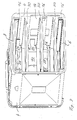
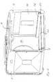
- the oven muffle lockable with a door, not shown 2 has two opposite walls 4, one Floor 6, a ceiling 8, a rear wall 10 and a front opening 12th
- Each of the walls 4 carries a removable wall parallel inside Support plate 14, which in at least one place Wall, which penetrates the ceiling, the floor and / or the rear wall, for example a presence detector trigger. At least one of the two support plates 14 is included a game mounted on the wall.
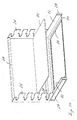
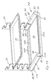
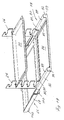
- Support plates 1,4 are two according to Figures 1 and 2 telescopic double pull-outs 16 fastened on top of what exactly horizontally or slightly inclined forward and if necessary can be made removable.
- the double statements 16 exist each from a fixed to the support plate 14 immovable Rail 18, a rail slidable thereon 20, an immovable rail 22 and one on it sliding rail 24. For this, sliding guides and / or roller guides such as ball or roller guides for Come into play.
- Holding device 26 immovable and preferably removable attached. Although not mandatory, are opposite holding devices 26 by a crossbar 28, which gives additional stability.
- the holding devices 26 according to FIGS. 1 and 2 can each Pick up two food supports 30. You have this for each level each have a horizontal section 32 on which the food support 30 with its rear floor area 34 can be pushed on is, one over the section 32 to form a gap 36 arranged horizontal section 38 to which a upward projection 40 of the rear upper Edge area 42 of the food carrier 30 can create the secure horizontal position, and a hook-like section 44, which is arranged in a recess arranged behind the projection 40. 46 of the rear upper edge area 48 of the food support 30 engages to pull it out horizontally to prevent the holding device 26. Section 32 closes a section 50 directed obliquely outwards that serves as a side guide.
- the levels in which the sections form elements for inclusion form the food support are selected such that also at only two independently movable holder pairs each of the recommended individually or in combination Baking room levels are available, for example the baking room levels 1, 3, 4 and 1 and 4.
- At least one holding device 26 of each level can at least an unlocking element, not shown, and a Not shown spring element can be assigned that itself relaxed after unlocking the retracted holding device 26 and supportively pushes it outwards.
- the mode of action is as follows:
- the holding device that carries the food support to unlock, so that the holding device 26 at least together with the rails 24 at least in sections automatically moves towards the front opening 12 and the food support 30 at least in sections in front of the oven in the oven 2 brings. If there is no spring element with lock or the holding device is not fully extended, the user grabs the food support 30 and pulls it open the double pull-outs 16 themselves.
- the food support 30 looks out of the oven 2, the user can not only start from the front, but also can also be captured from the sides, especially then is of great value if the food support (according to e.g. fully extended) should be removed.
- the food support 30 is tilted slightly upwards, so that the hook-like sections 44 of the holding devices 26 from the recesses 46 of the rear upper edge regions 48 of the food support, and then pulled forward.
- the food support 30 is between the side Guide sections 50 from obliquely above into the Columns 36 of the holding devices 26 introduced and on their horizontal sections 32 put on and finally after pushed behind until the recesses 46 under the hook-like Sections 44 are located. Then you move the Food carrier down until it is on the underside of the horizontal sections 32 rests with his after protrusions 40 extending at the horizontal portions 38 rests and with its recesses 46 the hook-like Sections. 44 has recorded.
- the Holding devices can be moved on the movable rails themselves added so that rail sections below the food support, even if it is spaced from it, completely eliminated.
- each double drawer 16 is a holding device 26 carries and in turn two holding devices one Level are connected by a crossbar 28.
- each of two food carriers 30 can also accommodate two holding devices 26, which are designed to accommodate only one food support 30 are and a receiving plane arranged above the rail level have, however, also below the rail level or in the rail level could be if the holding device for example, slidably added to the rails is.
- Holding devices 26 with only one receptacle for only one Food carriers 30 are easily telescopic due to their dimensions Systems made of one another and / or displaceable Rails can be integrated. So the last one can movable rail, for example, directly to the exchangeable one Inclusion of a food support from behind and / or from the Pages ago be formed.
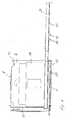
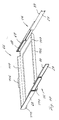
- Both versions can according to Figures 5 and 6 to the lowest movable rails 24 a horizontal plate 52, for example made of glass or glass ceramic, wear between a grill area that is above one above the floor 6 arranged grill radiator 54 and a loading area, who is at least partially in front of the oven 2 is located, is displaceable.
- a grill plate can however also on the lowest movable rails 20 or be arranged on the lowest holding device 26.
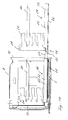
- a muffle is shown in the the support plates 14 individual extracts 58 from one on the support plate 14 immovable rail 60 and the holding device (26) receiving movable rail 62.
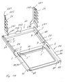
- FIGS. 9 to 18 show a muffle 64, in which the double pull-outs are not arranged on supports 14 which on the Hang walls 4 of the oven muffle, but on a support 66, which is on the floor 6 of the oven muffle 64.
- the carrier 66 For the Case that a bottom heat radiator is located above the bottom 6 of the oven muffle 64 is the carrier 66 as a horizontal Frame formed that surrounds the bottom heat radiator and possibly towered upwards. Regardless, points the carrier 66 has two parallel walls on its opposite sides flat sections 68, the inside of which the fixed inner rails 18 of the double pull-outs 16 (or of Single extensions).
- FIG. 9 to 11 is facing each other Inside of the movable outer rails 24 of the double pull-outs 16 (or of individual extracts) the holding devices (Holding combs) 26 supporting base 70 attached, the here as a horizontal frame with flat parallel to the wall Sections 72 for rail fastening and a circumferential one 'Support 74 designed to accommodate a plate 76 horizontally is made of glass,. glass ceramic, ceramic and stone or Like. Or also consist of metal and for example in retracted state of the cover one arranged above the floor Lower heat radiator and, if necessary, the recording of food to be cooked, especially grilled food and / or can serve from food carriers.
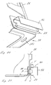
- FIGS. 12 to 18 it is possible to move the outer ones Rails 24 of the double pull-out 16 (or single pull-out) a lower part 78 carrying the holding devices 26 preferably immovable (but possibly also displaceable) put this on here as a horizontal frame Support surfaces 80 for resting on the top of the rails 24 and an already described rotating edition 74 for Recording a plate 76 already described is formed is.
- the immovability of the base 78 with respect to the rails 24 are through recesses 82 in the bearing surfaces 80 realized, in the elevations 84 of the rails 24 of intervene below.
- the lower part 78 is made of sheet metal, on the flat or frame-like central horizontal region 86 follow each other in parallel and in order vertical portions 88 at the top, outwardly extending portions horizontal sections 90 and down again connect vertical sections 92 which together are U-shaped Form cross-sections that face the user to, through vertical and interconnected sheet metal sections 94 are closed.
- This wrapper protects in retracted state (Fig. 12 and 13) the pull-outs (here double pull-outs 16) and in the extended state (Fig. 14) at least the outer ones that are the farthest out of the furnace muffle Rails (here rails 24) pre-spraying food.
- the holding devices 26 have at their lower ends the walls 4 technological bends with horizontal sections 96 on the sections 90 of the lower part 78 are placed, and vertical sections 98 to the Sections 88 of the lower part 78 can be applied.
- the carrier 66 is made of sheet metal, from the surface of which or frame-like central region 100 on the one hand the flat wall-parallel sections 68 on both sides extend above to their mutually facing inner sides the fixed rails 18 of the pull-outs 16 at least essentially to take up horizontally, for example a little inclined at the front, and on the other hand at the front Section 102 extends parallel to the rear wall downward, for example a bottom heat radiator arranged above the floor 6 to cover up front. Finally, too on the back a section 104 parallel to the rear wall extend diagonally at the top, where another, narrower section 106 connects vertically upwards, to hang the carrier behind the rear wall 10.
- both the carrier and the lower part can be Manufacture from die-cast aluminum.
- the user Before pyrolysis or the conventional tick Cleaning the oven muffle 64 and / or the conventional or dishwasher cleaning of the lower part 70 or 78 and / or the holding devices 26 and / or the carrier 66 the user can remove the holding parts (holding combs) 26 from the lower part Remove 70 or 78 and / or the lower part 70 or 78 with or remove from the support 66 without holding parts-26 and / or the carrier 66 with or without the lower part 70 or 78 and / or Remove the holding devices 26 from the oven muffle 64.
- the carrier 66 In order to be able to remove the carrier 66, it is first on the Tilt the front slightly upward until its rear sections 10.8 or 106 slide out of the recess in the rear wall 10.
- the oven muffle 64 is loaded in reverse Order by first placing the back ones in a first step Sections 108 and 106 by lifting the support in front 66 inserted into the recesses in the rear wall 10 and by subsequently lowering the carrier 66 behind the rear wall 10 are brought and in a second step the lower part 70 or 78 to the rear, upward-facing tabs of the rails 24 and in this way on the rails 24 is imposed that their surveys 84 from below into the Engage recesses in the lower part 70 or 78.
- the muffle 2 according to the Figures 1 to 8, the holding devices 26 of the rails 24th and / or this from the support plates 14 and / or this from the Walls. 4 remove.
- the Carrier 66 of the oven muffle 64, the walls 4 and / or Reach through floor 6 and / or rear wall 10 to presence detectors trigger.
- Both the support plates 14 and latching means can also be assigned to the carriers 66 be with the locking means of the oven 2 or 64 cooperate to release the support plates 14 from the walls 4 the oven muffle 2 or a tipping out of the carrier 66 to prevent the oven muffle 64.
- a lower part 78 is provided, that do not hang up from above, but from the front on the can slide movable rails 24.
- In the horizontal cover areas 90 of the lower part 78 extend in the direction of movement of the rails 24 slots S, which are pushed open Condition with the vertical pockets .T of the forms P aligned. Also in the frame-like area 86 of the lower part 78 slots S 'extend, but transversely to the direction of movement.
- the holding devices 26 have in addition to the first vertical Sections VA1, which are essentially in the direction of movement extend and the food support in several levels record second vertical sections VA2 which extend from the back of the first sections VA1 transverse to the direction of movement to extend towards each other.
- second vertical sections VA2 which extend from the back of the first sections VA1 transverse to the direction of movement to extend towards each other.
- At the lower ends of the tabs LA1 are formed on vertical sections VA1 corresponding to the lower ends of the vertical sections VA2 LA2 tabs.
- a carrier 112 may be provided, which is also on the floor 6 can be put on, but instead of pull-out systems in one (Fig. 22) or more levels (Fig. 23) one or more horizontal Has raceways 114 on or with rollers 116 Roll out the fitted holding devices 118 out of the oven muffle or can roll into it.
- the holding devices 118 located opposite each level can movable independently of each other and for example only be connected to each other by the food support 30. she but can also be connected by webs or surfaces that for example, have cooling air openings. With the holding devices 118 of FIG. 22 and that of the upper level of the figure 20 four food carriers can be placed on top of each other in levels record with the holding device 118 of the lower 23 only one level.
- the carriers 66 and 112 are separate or in the form of training the feet not shown shaped elements and / or locking means assignable, which with form elements, for example embossing, and / or locking means of the oven muffle 64, for example of the floor 6, cooperate to a predetermined installation position to secure.
Landscapes
- Engineering & Computer Science (AREA)
- Chemical & Material Sciences (AREA)
- Combustion & Propulsion (AREA)
- Mechanical Engineering (AREA)
- General Engineering & Computer Science (AREA)
- Baking, Grill, Roasting (AREA)
Abstract
Description
- jeweils einen oder mehrere wechselbare Gargutträger in einer oder mehreren Ebenen an ihren zur Muffelrückwand weisenden hinteren Bereichen wechselbar aufnehmen können und
- an und/oder mittels erster Führungen, die gegenüber liegen den Wandungen und/oder der Decke und/oder dem Boden der Garofenmuffel zugeordnet sind, zwischen einer hinteren Position, in der sich die Gargutträger in einem Garbereich befinden, und einer vorderen Position, in der sich die Gargutträger in einem Wechselbereich befinden, im wesentlichen horizontal bewegbar sind.
Die Verbindungen zwischen den Halteeinrichtungen können als Stege und/oder horizontale Rahmen und/oder horizontale Platte(n) und/oder Handhabungen, insbesondere Kunststoffhandhabungen, ausgebildet sein. Sie sind vorzugsweise auf die ersten Führungen auflegbar und/oder zwischen die ersten Führungen bringbar und/oder von vorn her auf die ersten Führungen insbesondere formschlüssig aufschiebbar und/oder an die ersten Führungen hängbar sind. Die Halteeinrichtungen sind an den Verbindungen insbesondere form- und/oder kraftschlüssig, beispielsweise durch Stecken, Klemmen, Eindrehen, Einklipsen oder Bajonettverschluss fest und/oder nutzerlösbar angeordnet und/oder zwischen einer zumindest im wesentlichen horizontalen und einer zumindest im wesentlichen vertikalen Lage schwenkbar. Sie können die Verbindungen mit den Führungen insbesondere form- und/oder kraftschlüssig, beispielsweise durch Stecken und dgl., fest und/oder nutzerlösbär verbinden.
Schließlich ist ein Garofen mit wenigstens einer der vorbeschriebenen Garofenmuffeln vorgesehen.
- einen oder mehrere wechselbare Gargutträger in einer oder mehreren Ebenen an ihren zur Muffelrückwand weisenden hinteren Bereichen wechselbar aufnehmen können und
- an und/oder mittels erster Führungen, die gegenüber liegenden Wandungen der Garofenmuffel zugeordnet sind, zwischen einer hinteren Position, in der sich die Gargutträger in einem Garbereich befinden, und einer vorderen Position, in der sich die Gargutträger in einem Wechselbereich befinden, im wesentlichen horizontal bewegbar sind. Die ersten Führungen sind vorzugsweise wenigstens einem zwischen einem unteren und einem oberen Bereich liegenden mittleren Bereich der Wandungen zugeordnet. Sie sind insbesondere direkt oder indirekt an den Wandungen der Garofenmuffel angeordnet und/oder an zweiten Führungen geführt, die ihrerseits direkt oder indirekt an den Wandungen der Garofenmuffel angeordnet sind. Die Aufnahmeebene(n) für die Gargutträger befinden sich insbesondere in und/oder unter und/oder über der Führungsebene der ersten Führungen.
- einen oder mehrere wechselbare Gargutträger in einer oder mehreren Ebenen an ihren zur Muffelrückwand weisenden hinteren Bereichen in horizontaler Lage wechselbar aufnehmen können und
- an und/oder mittels dritter Führungen, die dem Boden der Garofenmuffel zugeordnet sind, zwischen einer hinteren Position, in der sich die Gargutträger in einem Garbereich befinden, und einer vorderen Position, in der sich die Gargutträger in einem Wechselbereich befinden, im wesentlichen horizontal bewegbar sind. Die dritten Führungen sind insbesondere direkt oder indirekt am Boden der Garofenmuffel angeordnet und/oder an vierten Führungen geführt, die ihrerseits direkt oder indirekt am Boden der Garofenmuffel angeordnet sind.
- einen oder mehrere wechselbare Gargutträger in einer oder mehreren Ebenen an ihren zur Muffelrückwand weisenden hinteren Bereichen in horizontaler Lage wechselbar aufnehmen können und
- an und/oder mittels fünfter Führungen, die der Decke der Garofenmuffel zugeordnet sind, zwischen einer hinteren Position, in der sich die Gargutträger in einem Garbereich befinden, und einer vorderen Position, in der sich die Gargutträger in einem Wechselbereich befinden, im wesentlichen horizontal bewegbar sind. Die fünften Führungen sind insbesondere direkt oder indirekt an der Decke der Garofenmuffel angeordnet und/oder an sechsten Führungen geführt, die ihrerseits direkt oder indirekt an der Decke der Garofenmuffel angeordnet sind.
Claims (29)
- Garofenmuffel mit einer oder mehreren Halteeinrichtungen (26, 118), die in einer oder mehreren Ebenen angeordnet sind undjeweils einen oder mehrere wechselbare Gargutträger (30) in einer oder mehreren Ebenen an ihren zur Muffelrückwand (10) weisenden hinteren Bereichen wechselbar aufnehmen können undan und/oder mittels erster Führungen, die gegenüber liegenden Wandungen (4) und/oder der Decke (8) und/oder dem Boden (6) der Garofenmuffel (2,. 64) zugeordnet sind, zwischen einer hinteren Position, in der sich die Gargutträger (30) in einem Garbereich befinden, und einer vorderen Position, in der sich die Gargutträger (30) in einem Wechselbereich befinden, im wesentlichen horizontal bewegbar sind.
- Garofenmuffel nach Anspruch 1, bei der die ersten Führungen direkt oder indirekt an den Wandungen (4) und/oder dem Boden (6) und/oder der Decke (8) der Garofenmuffel (2, 64) insbesondere fest und/oder nutzerlösbar angeordnet und/oder an zweiten Führungen geführt sind, die ihrerseits direkt, oder indirekt an den Wandungen (4) und/oder dem Boden (6) und/oder der Decke (8) der Garofenmüffel (2, 64) insbesondere fest und/oder nutzerlösbar angeordnet sind.
- Garofenmuffel nach Anspruch 2, bei der die ersten und/oder zweiten Führungen direkt oder indirekt an einem oder mehreren Trägern (14, 66, 112) insbesondere fest und/oder nutzerlösbar angeordnet sind, die ihrerseits an den Wandungen (4) und/oder dem Boden (6) und/oder der Decke (8') der Garofenmuffel (2, 64) insbesondere fest und/oder nutzerlösbar angeordnet sind.
- Garofenmuffel nach Anspruch 3, bei der die Träger (14, 66, 112) als Streben und/oder Rahmen und/oder Gitter und/oder Bleche ausgebildet sind.
- Garofenmuffel nach Anspruch 4, bei der der Rahmen (66, 112) auf den Boden (6) aufsetzbar ist und insbesondere einen über dem Boden (6) angeordneten Unterhitzeheizkörper umgibt und insbesondere nach oben überragt.
- Garofenmuffel nach einem der Ansprüche 1 bis 5, bei der die ersten Führungen als feste Schienen (114) ausgebildet sind, um insbesondere die Halteeinrichtung(en) (118) direkt oder indirekt beweglich aufzunehmen, und/oder als Auszüge ausgebildet sind, die jeweils zwei relativ zueinander bewegliche Schienen (22, 24 bzw. 60, 62) aufweisen, um insbesondere die Halteeinrichtung(en) (26) direkt oder indirekt an bzw. auf der beweglichen Schiene (24 bzw. 62) beweglich oder unbeweglich aufzunehmen.
- Garofenmuffel nach einem der Ansprüche 2 bis 6, bei der die zweiten Führungen als Auszüge ausgebildet sind, die jeweils zwei relativ zueinander bewegliche Schienen (18, 20) aufweisen.
- Garofenmuffel nach Anspruch 7, bei der eine erste und eine zweite Führung einen Doppelauszug (16) bilden.
- Garofenmuffel nach einem der Ansprüche bis 8, bei der der oder die Gargutträger (30) an ihren zur Rückwand (10) weisenden hinteren Bereichen von hinten her und/oder von den Seiten her wechselbar aufnehmbar sind.
- Garofenmuffel nach einem der Ansprüche-1 bis 9, bei der der oder die Gargutträger (30) in die Halteeinrichtung(en) (26, 118) einhängbar und/oder einsteckbar und/oder einschiebbar sind.
- Garofenmuffel nach einem der Ansprüche 1 bis 10, bei der die Halteeinrichtungen) (26, 118) erste Formelemente (32, 36, 38, 44) aufweisen, die mit zweiten Formelementen (34, 40, 46, 48) der Gargutträger (30) zusammenwirken, um deren Einhängeebene und horizontale Lage zu sichern.
- Garofenmuffel nach einem der Ansprüche 1 bis 11, bei der die Halteeinrichtung(en) (26, 118) eine den hinterren Bereich der Gargutträger (30) nach unten abstützenden Einschubbereich aufweisen.
- Garofenmuffel nach einem der Ansprüche 1 bis 12, bei der die Halteeinrichtung(en) (26, 118) einen den hinteren Bereich der Gargutträger (30) nach oben abstützenden Bereich aufweisen.
- Garofenmuffel nach einem der Ansprüche 1 bis 13; bei der die Halteeinrichtung(en) (26, 118) einen Bereich aufweisen, der den hinteren Bereich der Gargutträger (30) in horizontaler Richtung festlegt.
- Garofenmuffel nach einem der Ansprüche 1 bis 14, bei der die Halteeinrichtung(en) (26) direkt oder indirekt an den ersten Führungen insbesondere fest und/oder nutzerlösbar angeordnet sind.
- Garofenmuffel nach einem der Ansprüche 1 bis 15, bei der die Halteeinrichtung(en) (26) direkt oder indirekt von oben her auf die ersten Führungen auflegbar und/oder zwischen die ersten Führungen einbringbar und/oder von vorn her auf die ersten Führungen insbesondere formschlüssig aufschiebbar und/oder an dien ersten Führungen anhängbar sind.
- Garofenmuffel nach einem der Ansprüche 1 bis 16, bei der den Gargütträgern (30) und/oder Gruppen von Gargutträgern (30) jeweils wenigstens eine Halteeinrichtung (26, 118) zugeordnet ist.
- Garofenmuffel nach einem der Ansprüche .1 bis 17, bei der den Gärgutträgern (30) und/oder Gruppen-von Gargutträgern (30) jeweils wenigstens zwei miteinander verbundene Halteeinrichtungen (26, 118) zugeordnet sind.
- Garofenmuffel nach Anspruch 18, bei der die Verbindungen zwischen den Halteeinrichtungen (26, 118) als Stege (28) und/oder horizontale Rahmen (70, 86) und/oder horizontale Platte(n) und/oder Handhabungen, insbesondere Kunststoffhandhabungen, ausgebildet sind.
- Garofenmuffel nach Anspruch 18 oder 19, bei der die Verbindungen zwischen den Hälteeinrichtungen (26,118) auf die Führungen auflegbar und/oder zwischen die Führungen bringbar rund/oder von vorn her auf die Führungen insbesondere formschlüssig aufschiebbar und/oder an die Führungen anhängbar sind.
- Garofenmuffel nach einem der Ansprüche 18 bis 20, bei der die Halteeinrichtungen (26, 118) an den Verbindungen insbesondere form- und/oder kraftschlüssig, beispielsweise durch Stecken, Klemmen, Eindrehen, Einklipsen oder Bajonettverschluß, fest und/oder nutzerlösbar angeordnet und/oder zwischen einer zumindest im wesentlichen vertikalen und einer zumindest im wesentlichen horizontalen Lage schwenkbar sind.
- Garofenmuffel nach einem der Ansprüche 18 bis 21, beider die Halteeinrichtungen die Verbindungen zwischen den Halteeinrichtungen mit den Führungen insbesondere form- und/oder kraftschlüssig, beispielsweise durch Stecken, Klemmen, Eindrehen, Einklipsen oder Bajonettverschluß, fest und/oder nutzerlösbar verbinden.
- Garofenmuffel nach einem der Ansprüche 1 bis 22, bei der den Gargutträgern (30) und/oder Gruppen von Gargutträgern (30) jeweils-wenigstens zwei voneinander unabhängige Halteeinrichtungen (26, 118) zugeordnet sind, die insbesondere durch die Gargutträger (30) verbindbar sind.
- Garofenmuffel nach einem der Ansprüche 1 bis 23, bei der sich die Aufnahmeebene für die Gargutträger (30) in und/oder unter und/oder über der Führungsebene der ersten Führungen befindet.
- Garofenmuffel nach einem der Ansprüche 1 bis 24, bei der die Gargutträger (30) oder Gruppen von Gargutträgern (30) mit den Halteeinrichtungen (26, 118) unabhängig voneinander horizontal bewegbar sind.
- Garofenmuffel nach einem der Ansprüche 1 bis 25, bei der sich der Garbereich vollständig hinter der Beschickungsöffnung (12) der Garofenmuffel (2, 64) und der Wechselbereich zumindest teilweise, vorzugsweise vollständig vor der Beschickungsöffnung (12) der Garofenmuffel (2, 64) erstreckt.
- Garofenmuffel nach einem der Ansprüche 1 bis 26, bei der sich die vordere Position der Halteeinrichtung(en) (26, 118) vollständig im Bereich der Öffnungsebene der Garofenmuffel (2, 64), insbesondere im wesentlichen oder vollständig hinter der Öffnungsebene (12), in der Öffnungsebene (12) oder im wesentlichen oder vollständig vor der Öffnungsebene (12) befindet.
- Garofenmuffel nach einem der Ansprüche 1 bis 27, bei der die in der untersten Ebene angeordneten Halteeinrichtung(en) (26, 118) und/oder Führungen direkt oder indirekt eine horizontale Platte (52) aus insbesondere Glaskeramik, Glas, Keramik, Stein, Metall oder dgl. tragen, die im eingefahrenen Zustand der Halteeinrichtungen (26, 118) und/oder Führungen einen über dem Boden (6) der Garofenmuffel (2) angeordneten Heizkörper, insbesondere Grillheizkörper, abdeckt und insbesondere der Aufnahme von Gargut und/oder Gargutträgern und/oder in rahmenartiger Ausbildung der Aufnahme einer weiteren Platte zur Aufnahme von Gargut und/oder Gargutträgern dient.
- Garofen mit wenigstens einer Garofenmuffel (2, 64) nach einem der Ansprüche 1 bis 28.
Priority Applications (1)
| Application Number | Priority Date | Filing Date | Title |
|---|---|---|---|
| EP10010278.9A EP2284447B1 (de) | 2002-06-17 | 2003-05-12 | Garofenmuffel |
Applications Claiming Priority (8)
| Application Number | Priority Date | Filing Date | Title |
|---|---|---|---|
| DE10226957 | 2002-06-17 | ||
| DE10226954 | 2002-06-17 | ||
| DE10226958 | 2002-06-17 | ||
| DE10226954 | 2002-06-17 | ||
| DE10226957 | 2002-06-17 | ||
| DE10226958 | 2002-06-17 | ||
| DE10241487A DE10241487A1 (de) | 2002-06-17 | 2002-09-07 | Garofenmuffel |
| DE10241487 | 2002-09-07 |
Related Child Applications (1)
| Application Number | Title | Priority Date | Filing Date |
|---|---|---|---|
| EP10010278.9A Division EP2284447B1 (de) | 2002-06-17 | 2003-05-12 | Garofenmuffel |
Publications (1)
| Publication Number | Publication Date |
|---|---|
| EP1376019A1 true EP1376019A1 (de) | 2004-01-02 |
Family
ID=29718661
Family Applications (1)
| Application Number | Title | Priority Date | Filing Date |
|---|---|---|---|
| EP03009823A Withdrawn EP1376019A1 (de) | 2002-06-17 | 2003-05-12 | Garofenmuffel |
Country Status (1)
| Country | Link |
|---|---|
| EP (1) | EP1376019A1 (de) |
Cited By (6)
| Publication number | Priority date | Publication date | Assignee | Title |
|---|---|---|---|---|
| WO2007000357A1 (de) | 2005-06-29 | 2007-01-04 | BSH Bosch und Siemens Hausgeräte GmbH | Hausgerät sowie gargutträger-haltevorrichtung für ein hausgerät |
| WO2007033924A1 (de) * | 2005-09-19 | 2007-03-29 | BSH Bosch und Siemens Hausgeräte GmbH | Gargerät |
| EP1818620A1 (de) * | 2006-02-10 | 2007-08-15 | Filippi S.r.l. | Backofen mit einem Backwagen mit integriertem Heizelement und Grillrosten |
| EP2236941A1 (de) * | 2009-03-28 | 2010-10-06 | Electrolux Home Products Corporation N.V. | Halterung für ausziehbare Backbleche und/oder Backroste |
| EP2042812A3 (de) * | 2007-09-25 | 2012-01-11 | BSH Bosch und Siemens Hausgeräte GmbH | Trägerrahmen |
| DE102011088088A1 (de) | 2011-12-09 | 2013-06-13 | BSH Bosch und Siemens Hausgeräte GmbH | Halterungsvorrichtung für Gargutträger |
Citations (4)
| Publication number | Priority date | Publication date | Assignee | Title |
|---|---|---|---|---|
| DE7505695U (de) * | 1975-02-25 | 1975-08-28 | Kueppersbusch F & Soehen Ag | Back und bratrohr |
| DE8915017U1 (de) * | 1989-12-21 | 1990-03-01 | Bosch-Siemens Hausgeräte GmbH, 8000 München | Vorrichtung zur Aufnahme und Halterung von Gargutträgern innerhalb einer Herdmuffel |
| FR2650372A1 (fr) * | 1989-07-28 | 1991-02-01 | Fagor S Coop Ltda | Four de cuisine perfectionne |
| DE19847727A1 (de) * | 1998-10-16 | 2000-04-27 | Aeg Hausgeraete Gmbh | Teleskopauszugsvorrichtung für Gargutträger im Garraum von Haushaltsbacköfen |
-
2003
- 2003-05-12 EP EP03009823A patent/EP1376019A1/de not_active Withdrawn
Patent Citations (4)
| Publication number | Priority date | Publication date | Assignee | Title |
|---|---|---|---|---|
| DE7505695U (de) * | 1975-02-25 | 1975-08-28 | Kueppersbusch F & Soehen Ag | Back und bratrohr |
| FR2650372A1 (fr) * | 1989-07-28 | 1991-02-01 | Fagor S Coop Ltda | Four de cuisine perfectionne |
| DE8915017U1 (de) * | 1989-12-21 | 1990-03-01 | Bosch-Siemens Hausgeräte GmbH, 8000 München | Vorrichtung zur Aufnahme und Halterung von Gargutträgern innerhalb einer Herdmuffel |
| DE19847727A1 (de) * | 1998-10-16 | 2000-04-27 | Aeg Hausgeraete Gmbh | Teleskopauszugsvorrichtung für Gargutträger im Garraum von Haushaltsbacköfen |
Cited By (7)
| Publication number | Priority date | Publication date | Assignee | Title |
|---|---|---|---|---|
| WO2007000357A1 (de) | 2005-06-29 | 2007-01-04 | BSH Bosch und Siemens Hausgeräte GmbH | Hausgerät sowie gargutträger-haltevorrichtung für ein hausgerät |
| WO2007033924A1 (de) * | 2005-09-19 | 2007-03-29 | BSH Bosch und Siemens Hausgeräte GmbH | Gargerät |
| EP1818620A1 (de) * | 2006-02-10 | 2007-08-15 | Filippi S.r.l. | Backofen mit einem Backwagen mit integriertem Heizelement und Grillrosten |
| EP2042812A3 (de) * | 2007-09-25 | 2012-01-11 | BSH Bosch und Siemens Hausgeräte GmbH | Trägerrahmen |
| EP2236941A1 (de) * | 2009-03-28 | 2010-10-06 | Electrolux Home Products Corporation N.V. | Halterung für ausziehbare Backbleche und/oder Backroste |
| CN102362123A (zh) * | 2009-03-28 | 2012-02-22 | 伊莱克斯家用产品股份有限公司 | 用于可抽取烤盘和/或烤架的支承件 |
| DE102011088088A1 (de) | 2011-12-09 | 2013-06-13 | BSH Bosch und Siemens Hausgeräte GmbH | Halterungsvorrichtung für Gargutträger |
Similar Documents
| Publication | Publication Date | Title |
|---|---|---|
| EP1225806B1 (de) | Gargutträgersystem für einen backofen | |
| DE10151899C1 (de) | Schienensystem für Gargutträger in einem Backofen | |
| DE10051153B4 (de) | Gargutträgersystem für einen Backofen | |
| DE10330348B4 (de) | Gargutträgerauszugsystem | |
| EP4293287B1 (de) | Teleskopauszug | |
| EP2284447B1 (de) | Garofenmuffel | |
| DE10241486B4 (de) | Garofenmuffel mit einem über dem Muffelboden angeordneten Unterhitzeheizkörper | |
| DE4446757C3 (de) | Back- und Bratofen mit einem Teleskopwagen | |
| DE4014823C2 (de) | Herd mit einer Backmuffel und mit einem auf Teleskopauszügen verschiebbaren Tragrahmen | |
| EP3781872B1 (de) | Backofen | |
| WO2016034442A1 (de) | Auszugssystem und haushaltsgargerät | |
| EP0952403A2 (de) | Backofen mit Teleskopauszug | |
| DE3924588C2 (de) | Backofen | |
| DE10241489A1 (de) | Teleskopartiges System und Auszug für einen Gargutträger | |
| EP4286749B1 (de) | Schnellbefestigungssystem für einen teleskopauszug | |
| EP1376018A1 (de) | Garofenmuffel zur Aufnahme mehrerer wechselbarer Gargutträger | |
| EP2320147A2 (de) | Garofenmuffel zur Aufnahme mehrerer wechselbarer Gargutträger | |
| EP1011380B1 (de) | Kücheneinrichtung mit oberteil und mit wenigstens einem unterbau, und wagen zum ein- und aushängen eines unterbau-moduls an einem oberteil | |
| EP1376017A1 (de) | Teleskopartiges System und Auszug für einen Gargutträger | |
| DE202014106054U1 (de) | Vorrichtung zur Auflage von Gargutträgern | |
| DE102011087219A1 (de) | Gargutträgerauszug | |
| DE102006027703A1 (de) | Elektrohaushaltsgerät | |
| DE102009002219A1 (de) | Hausgerät | |
| DE102005030392A1 (de) | Hausgerät sowie Garguträger-Haltevorrichtung für ein Hausgerät | |
| CH696555A5 (de) | Garofenmuffel mit einem über dem Muffelboden angeordneten Unterhitzeheizkörper. |
Legal Events
| Date | Code | Title | Description |
|---|---|---|---|
| PUAI | Public reference made under article 153(3) epc to a published international application that has entered the european phase |
Free format text: ORIGINAL CODE: 0009012 |
|
| 17P | Request for examination filed |
Effective date: 20031024 |
|
| AK | Designated contracting states |
Kind code of ref document: A1 Designated state(s): AT BE BG CH CY CZ DE DK EE ES FI FR GB GR HU IE IT LI LU MC NL PT RO SE SI SK TR |
|
| AX | Request for extension of the european patent |
Extension state: AL LT LV MK |
|
| AKX | Designation fees paid |
Designated state(s): AT BE BG CH CY CZ DE DK EE ES FI FR GB GR HU IE IT LI LU MC NL PT RO SE SI SK TR |
|
| 17Q | First examination report despatched |
Effective date: 20050304 |
|
| RAP1 | Party data changed (applicant data changed or rights of an application transferred) |
Owner name: ELECTROLUX HOME PRODUCTS CORPORATION N.V. |
|
| RAP1 | Party data changed (applicant data changed or rights of an application transferred) |
Owner name: ELECTROLUX HOME PRODUCTS CORPORATION N.V. |
|
| STAA | Information on the status of an ep patent application or granted ep patent |
Free format text: STATUS: THE APPLICATION HAS BEEN WITHDRAWN |
|
| 18W | Application withdrawn |
Effective date: 20160118 |