EP1375751A1 - Apparatus for making plane surfaces from bulk building material - Google Patents
Apparatus for making plane surfaces from bulk building material Download PDFInfo
- Publication number
- EP1375751A1 EP1375751A1 EP02405523A EP02405523A EP1375751A1 EP 1375751 A1 EP1375751 A1 EP 1375751A1 EP 02405523 A EP02405523 A EP 02405523A EP 02405523 A EP02405523 A EP 02405523A EP 1375751 A1 EP1375751 A1 EP 1375751A1
- Authority
- EP
- European Patent Office
- Prior art keywords
- support
- trigger
- receiver
- rail
- height
- Prior art date
- Legal status (The legal status is an assumption and is not a legal conclusion. Google has not performed a legal analysis and makes no representation as to the accuracy of the status listed.)
- Withdrawn
Links
Images

Classifications
-
- E—FIXED CONSTRUCTIONS
- E01—CONSTRUCTION OF ROADS, RAILWAYS, OR BRIDGES
- E01C—CONSTRUCTION OF, OR SURFACES FOR, ROADS, SPORTS GROUNDS, OR THE LIKE; MACHINES OR AUXILIARY TOOLS FOR CONSTRUCTION OR REPAIR
- E01C19/00—Machines, tools or auxiliary devices for preparing or distributing paving materials, for working the placed materials, or for forming, consolidating, or finishing the paving
- E01C19/22—Machines, tools or auxiliary devices for preparing or distributing paving materials, for working the placed materials, or for forming, consolidating, or finishing the paving for consolidating or finishing laid-down unset materials
- E01C19/42—Machines for imparting a smooth finish to freshly-laid paving courses other than by rolling, tamping or vibrating
-
- B—PERFORMING OPERATIONS; TRANSPORTING
- B28—WORKING CEMENT, CLAY, OR STONE
- B28B—SHAPING CLAY OR OTHER CERAMIC COMPOSITIONS; SHAPING SLAG; SHAPING MIXTURES CONTAINING CEMENTITIOUS MATERIAL, e.g. PLASTER
- B28B1/00—Producing shaped prefabricated articles from the material
- B28B1/29—Producing shaped prefabricated articles from the material by profiling or strickling the material in open moulds or on moulding surfaces
-
- E—FIXED CONSTRUCTIONS
- E01—CONSTRUCTION OF ROADS, RAILWAYS, OR BRIDGES
- E01C—CONSTRUCTION OF, OR SURFACES FOR, ROADS, SPORTS GROUNDS, OR THE LIKE; MACHINES OR AUXILIARY TOOLS FOR CONSTRUCTION OR REPAIR
- E01C19/00—Machines, tools or auxiliary devices for preparing or distributing paving materials, for working the placed materials, or for forming, consolidating, or finishing the paving
- E01C19/004—Devices for guiding or controlling the machines along a predetermined path
- E01C19/006—Devices for guiding or controlling the machines along a predetermined path by laser or ultrasound
-
- E—FIXED CONSTRUCTIONS
- E04—BUILDING
- E04F—FINISHING WORK ON BUILDINGS, e.g. STAIRS, FLOORS
- E04F21/00—Implements for finishing work on buildings
- E04F21/20—Implements for finishing work on buildings for laying flooring
- E04F21/24—Implements for finishing work on buildings for laying flooring of masses made in situ, e.g. smoothing tools
- E04F21/241—Elongated smoothing blades or plates, e.g. screed apparatus
- E04F21/242—Elongated smoothing blades or plates, e.g. screed apparatus with vibrating means, e.g. vibrating screeds
Definitions
- the invention relates to a device for producing a flat surface pourable, hardening building material, such as concrete, asphalt or the like, with one extending transversely to the direction of travel, the building material after a reference plane created by a measuring device Trigger beam, which is connected to a support device at the lateral ends is.
- a measuring device Trigger beam which is connected to a support device at the lateral ends is.
- FIG. 1 Facilities of this type are mainly used in the construction industry, where flat shelves, ceilings, and driveways are to be made or made from one or more building materials.
- measuring staffs are used for measuring such construction objects, to which a laser receiver is attached relative to a rotating laser beam transmitter arranged on a tripod. The latter sends a light or. Laser beam so as to form a laser or reference plane.
- a leveled support for the trigger bar which can be moved indirectly, is created at two opposite edges that delimit the plane to be manufactured.
- the trigger beam which is supported on rollers and on which at least one trigger rail is attached, moves transversely to the direction of travel.
- a rotating shaft mounted parallel to the extension of the trigger beam releases a vibration effect on the trigger beam, which is transferred to the building material and is increasingly compacted as a pulp-like building material.
- laser beam leveling devices can also be viewed from the horizontal measure deviating or sloping areas and in the manner described finished.
- This measurement technique uses the present invention with the object and thus breaks new ground; by laying on a plane to be manufactured Surface made of one building material, less effort required with greater accuracy is.
- the trigger beam is fastened to the support device in a height-adjustable manner and has at least one receiver which is arranged in the vicinity of the support device and is connected to a transmitter of the measuring device and is computer-controlled connected to an adjusting device which keeps the height of the trigger beam constant.
- This device makes it easy to measure a flat surface to be manufactured without creating a lateral support leveled to move the device, and considerably simplifies the necessary preparatory work. This applies to the production of floors, ceilings in buildings, for example residential buildings, industrial buildings or parking garages, as well as for slopes or other driveways.
- the support device is preferably designed to be slidable in order to Bumps in the support are necessary for moving the facility To be able to keep tractive forces within limits.
- a laser beam leveling device generating a reference plane is suitable as the measuring device; but there are also others, a reference plane through a (light) beam generating measuring devices applicable.
- the receivers are advantageously designed as measuring sensors and with a computer connected, in the event of a deviation from the Edition height of the device control signals to one with the adjusting device connected control transfers, with the computer and control unit in the Proximity range of the adjustment device can be arranged.
- the support device acting at the lateral ends of the trigger device in each case has at least one adjusting device assigned to a trigger rail.
- each trigger rail on the side ends of the trigger beam one with one Receiver is assigned to the computer-connected connected adjustment device convey a high quality of work.
- the runners are expediently fastened to support members of the support device, so as to favor the sliding properties of the device, being for two support members at one end of the support beam a skid or for each support member one runner can be provided on one side of the trigger bar.
- a compact design of the device can be achieved if the on the support device, a trigger beam connected to a receiver Computer-controlled adjustment device.
- a support member one with a skid, one connected to the trigger beam Support has vertically adjustable outrigger.
- the support leg is preferably in the support to favor the support guided, so that dynamically acting forces for the support device are tolerated.
- the adjustment device could be an alternative to the electric or internal combustion engine through a hydraulically or pneumatically operated piston-cylinder unit be formed by a piston rod with the support leg of a support member is connected to the drive.
- the alignment device expediently has a support element on which the receiver is attached, so that optimal accessibility to the Facility is reachable.
- the lower one End of the alignment bar or bar, with the trigger bar connected support element with the reference height or the trigger level of the trigger bar is flush.
- the Support devices forming support devices each with a receiver the measuring device is assigned to the alignment device.
- the support element resettable resp. is designed to be adjustable upwards.
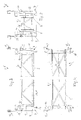
- Fig. 2 illustrates a device 1 for producing a flat surface 2 or plane (Fig.1) respectively.
- Surface made of a pourable building material 3, such as concrete, asphalt or the like, which solidifies after a certain dwell time in such a way that it can be loaded or driven on.
- the device 1 has a trigger bar 4, on the underside of which at least one, here two parallel trigger rails 5 are fixedly arranged (see also FIGS. 3 and 4).
- a support frame 6 is provided with struts, which has a triangular cross section.
- Motor-driven winches are arranged on the lateral ends of the take-off beam 4, by means of which the device 1 is moved transversely to its extension by winding up a pulling rope anchored at the end of the surface to be manufactured.
- the trigger bar 4 has a vibration wave (not shown) which runs parallel to the trigger rails 5 and which promotes the compaction of the building material 3 and produces a homogeneous structure.
- the trigger beam 4 is designed according to the invention at the lateral ends with a support device 7 with which it is connected in a height-adjustable manner is.
- the support device 7 in the device 1 shown consists of four support members 8, on which the trigger beam 4 is fastened in a height-adjustable manner.
- the trigger bar 4 is by an adjusting device 9, which will be described later, with the support device 7 and. the support members 8 connected.
- the adjustment device 9 has a support 10 connected to the trigger bar 4, to which a receiver 13 connected via a light beam 14 to a transmitter 11 of a measuring device 12 is fastened and which is guided through the support member 8.
- the measuring device 12 is, for example, a laser beam leveling device described briefly at the beginning, which is used, among other things, for the production of horizontal and inclined floors. Such laser beam leveling devices are described, for example, in CH-A-691708 and other patent literature.
- the rotating transmitter 11 generates a horizontal or inclined laser plane, according to which a receiver 13 can be aligned or aligned. are automatically adaptable in the present facility.
- a computer 15 and a control 16 connected to it are provided, which ensure that the receiver 13, which deviates from the emitted reference plane when the height of the support device 7 changes, makes a corresponding correction of the distance or the distance practically without delay via the adjustment device 9 between receiver 13 and support device 7 respectively.
- Support member / s 8 is initiated to keep the height of the trigger beam 4 constant. This means that the trigger beam 4 / trigger rail / s 5 resting on the building material 3 according to the measured or. leveled reference height 17 remain aligned. This principle allows precise processing of the building material 3 with less attention than is required for a leveled surface to be prepared.
- the device 1 according to the invention can be placed on a reinforcement and moved and for this purpose has runners 18 resting on the lower end of the support device 7 or on the underside of the support members 8, which allow the device 1 to slide even on an uneven surface, such as reinforcement nets , a formwork, lean concrete, grown underlay resp. grown soil or the like. Compacted base without affecting the manufacturing quality by making the device 1 easy to move.
- the receiver 13 which acts as a transmitter, and which is attached to the lateral ends of the trigger beam 4 and thus firmly connected to the trigger rail (s) 5 on the one hand and visually connected to the transmitter 11 of the laser beam leveling instrument 12, is also connected to a computer 15 which evaluates the deviations from the reference plane or the reference height 17 that occur during the movement of the device 1 and transmits corresponding control signals to the controller 16, which in turn corrects the distance between the trigger bar 4 or trigger rail (s) 5 by means of the support device 7 or the support members 8 adjustably connected to the adjustment device (s) 9.
- four support members 8 are provided as support devices 7, and each support member 8 is assigned a receiver 13, an adjusting device 9 and computer 15, as well as control 16, which acts on the support device 8.
- the rectangular arrangement of the support members according to FIG. 4 in plan view 8 allows automatic leveling or keeping the height constant the deduction bar 4 respectively.
- the trigger rail / s 5 in the production position, so that the latter during the movement of the device 1 on a reinforcement, one Formwork or other underlay a coplanar plane to the reference height respectively. form a plane parallel to the emitted reference plane.
- the runners 18 of the support device 7 are each aligned according to the direction of travel F and are arranged pivotably about an axis directed transversely to the direction of travel F for easier overcoming bumps or in order to be able to overcome differences in height on the support more easily.
- the runners 18 form part of the support members 8.
- two runners 8 can be assigned a runner 18 on a lateral end of the trigger beam 4 or a runner 18 can be assigned to each support member 8 on a lateral end of the trigger beam 8.
- the support members 8 in turn have a support leg 19 which interacts with an adjusting device 9 and is guided in the support 10 connected to the trigger beam 4.
- an electric motor 20 connected to the controller 16 is attached, which is preferably designed as a geared motor.
- an adjusting spindle 21 is fastened, which plunges into the upper end of the support leg 19, which is designed as a threaded sleeve 22.
- a tubular section of the support 10 connected to the trigger beam 4 forms a guide for the support leg 19.
- FIG. 5 shows an adjusting device 9 designed with a piston-cylinder unit 23 attached to the support 10.
- the support leg 19 is designed in the upper region as a guide piston 24, which is surrounded by a cylindrical part 25 of the support 10 is.
- the upper end of the guide piston 24 is coupled to a piston rod 25 which can be acted upon by a pressure medium from two sides in a cylinder 26 of the piston-cylinder unit 23. The drive of the piston rod 25, respectively.
- a directional control valve 27 which can be actuated by a control 16 and is connected to the piston-cylinder unit 23 via lines 32, 33, and by the receiver 13 of a measuring device 12 which is connected to a computer 15.
- the directional control valve 27 is on a pressure source, not shown, and a liquid reflux container connected. Should the base of the device 1 change in height on the movement path, for example in such a way that the support device 7 or.
- the receivers 13 of the measuring device 12 trigger a control signal which causes the control 16 to lower the trigger bar 4 or compensates for the height difference with respect to the reference height 17 which has arisen at the receiver 13 with respect to the transmitter 11, such that that the trigger rail / s 5 remain at a constant height.
- the device 1 To set up the device 1 on the building object, it is leveled to a or non-leveled, fixed storage space, for example reinforcement, formwork or parked as already mentioned.
- a measuring device 12 Outside the area to be manufactured 2 is by the transmitter 11 of a measuring device 12, for example by a rotating laser beam of a laser beam leveling device, one over the construction site extending reference plane is created, to which the receiver 13 to be aligned are.
- This work process that prepares the production work can be done with the help the height adjustability of the transmitter 11 attached to a tripod and the Adjustment device 9 are carried out with the one adjustable receiver 13 supporting support 10 is connected.
- the receiver 13 can be connected to the Support 10 releasably connected holding device can be adjustably attached. It is advantageous if the setting of the device 1 to the reference level in close to the reference height 17.
- the adjustment or setup work can be shortened by an alignment device 28 and facilitate when the aligner 28 is made from one on the trigger beam 4 releasably attached support member 29, on which a receiver 13th is attached.
- the alignment device 28 is used to provide the setup process the device 1 before manufacturing as well as aligning the device 1 according to the reference height 17 or the reference plane of the measuring device 12 during manufacturing.
- the alignment device 28 is set to the reference height 17 and then the receiver 13, which is adjustably attached to the support element 29, is adjusted to the emitted reference plane of the transmitter 11. Then the alignment device 28 is inserted with the support element 29 into a holder 30 provided on the support 10, so that the lower end of the support element 29 with the trigger plane or. is flush with the plane formed by the trigger rails 5 of the supporting beam 4 or adjoins this.
- the support element 29 is formed by a receiving device which is complementary to the holder 30, so that its lower edge always assumes the same position when the support element 29 is inserted in the holder 30.
Landscapes
- Engineering & Computer Science (AREA)
- Architecture (AREA)
- Civil Engineering (AREA)
- Structural Engineering (AREA)
- Manufacturing & Machinery (AREA)
- Chemical & Material Sciences (AREA)
- Ceramic Engineering (AREA)
- Mechanical Engineering (AREA)
- Physics & Mathematics (AREA)
- Optics & Photonics (AREA)
- Forms Removed On Construction Sites Or Auxiliary Members Thereof (AREA)
Abstract
Description
Die Erfindung betrifft eine Einrichtung zur Herstellung einer planen Fläche aus schüttfähigem, aushärtendem Baustoff, wie Beton, Asphalt oder dgl., mit einem sich quer zur Fortbewegungsrichtung erstreckenden, den Baustoff nach einer durch eine Messvorrichtung erstellten Bezugsebene ausgleichend abtragenden Abzugsbalken, der an den seitlichen Enden mit einer Abstützvorrichtung verbunden ist.The invention relates to a device for producing a flat surface pourable, hardening building material, such as concrete, asphalt or the like, with one extending transversely to the direction of travel, the building material after a reference plane created by a measuring device Trigger beam, which is connected to a support device at the lateral ends is.
Einrichtungen dieser Art werden vornehmlich im Baugewerbe eingesetzt, wo ebene
Abstellflächen, Decken, Fahrstrassen aus einem oder mehreren Baustoffen herzustellen
oder zu fertigen sind.
Für das Vermessen solcher Bauobjekte werden bekanntlich Messlatten verwendet,
an denen ein Laserempfänger gegenüber einem auf einem Stativ angeordneten,
rotierenden Laserstrahlsender befestigt ist. Letzterer sendet in horizontaler Richtung
einen Licht- resp. Laserstrahl aus, um so eine Laser- bzw. Bezugsebene zu
bilden. D.h., es wird von der Bezugsebene ausgehend an zwei sich gegenüberliegenden,
die zu fertigende Ebene begrenzenden Rändern eine nivellierte Auflage
für den darauf mittelbar verschiebbaren Abzugsbalken erstellt. Auf dieser Auflage
bewegt sich quer zur Fortbewegungsrichtung der auf Rollen abgestützte Abzugsbalken,
an dem wenigstens eine Abzugsschiene befestigt ist. Facilities of this type are mainly used in the construction industry, where flat shelves, ceilings, and driveways are to be made or made from one or more building materials.
As is known, measuring staffs are used for measuring such construction objects, to which a laser receiver is attached relative to a rotating laser beam transmitter arranged on a tripod. The latter sends a light or. Laser beam so as to form a laser or reference plane. In other words, starting from the reference plane, a leveled support for the trigger bar, which can be moved indirectly, is created at two opposite edges that delimit the plane to be manufactured. On this support, the trigger beam, which is supported on rollers and on which at least one trigger rail is attached, moves transversely to the direction of travel.
Eine parallel zur Erstreckung des Abzugsbalkens gelagerte rotierende Welle löst eine Vibrationswirkung auf den Abzugsbalken aus, die auf den Baustoff übertragen wird und diesen zusehends als breiartigen Baustoff verdichtet.A rotating shaft mounted parallel to the extension of the trigger beam releases a vibration effect on the trigger beam, which is transferred to the building material and is increasingly compacted as a pulp-like building material.
Mit aufwändigeren Laserstrahl-Nivelliergeräten lassen sich auch von der Horizontalen abweichende bzw. abfallende Flächen vermessen und auf die beschriebene Art fertigen.With more elaborate laser beam leveling devices can also be viewed from the horizontal measure deviating or sloping areas and in the manner described finished.
Diese Vermessungstechnik nutzt die vorliegende Erfindung mit der gestellten Aufgabe und beschreitet damit neue Wege; indem bei einer zu fertigenden ebenen Fläche aus einem Baustoff, bei grösserer Genauigkeit weniger Aufwand erforderlich ist.This measurement technique uses the present invention with the object and thus breaks new ground; by laying on a plane to be manufactured Surface made of one building material, less effort required with greater accuracy is.
Erfindungsgemäss wird diese Aufgabe dadurch gelöst, dass der Abzugsbalken an
der Abstützvorrichtung höhenverstellbar befestigt ist und wenigstens einen im Näherungsbereich
der Abstützvorrichtung angeordneten, mit einem Sender der Messvorrichtung
verbundenen Empfänger aufweist, der mit einer die Höhenlage des
Abzugsbalkens konstant haltenden Verstellvorrichtung rechnergesteuert verbunden
ist.
Diese Einrichtung ermöglicht ein einfaches Vermessung einer zu fertigenden, planen
Fläche ohne ein Erstellen einer zur Verschiebung der Einrichtung nivellierten
seitlichen Auflage, und erleichtert die notwendigen Vorarbeiten in beträchtlichem
Mass.
Dies gilt sowohl für die Herstellung von Böden, Decken in Gebäuden, beispielsweise
Wohnhäuser, Industriebauten oder Parkhäusern wie auch für Pisten oder
andere Fahrstrassen.According to the invention, this object is achieved in that the trigger beam is fastened to the support device in a height-adjustable manner and has at least one receiver which is arranged in the vicinity of the support device and is connected to a transmitter of the measuring device and is computer-controlled connected to an adjusting device which keeps the height of the trigger beam constant.
This device makes it easy to measure a flat surface to be manufactured without creating a lateral support leveled to move the device, and considerably simplifies the necessary preparatory work.
This applies to the production of floors, ceilings in buildings, for example residential buildings, industrial buildings or parking garages, as well as for slopes or other driveways.
Es erweist sich als vorteilhaft, wenn der Abzugsbalken durch die Verstellvorrichtung mit der Abstützvorrichtung verbunden ist, indem sich eine günstige konstruktive Bau- und Arbeitsweise verwirklichen lässt.It proves to be advantageous if the trigger bar by the adjusting device is connected to the support device by an inexpensive constructive Construction and working method can be realized.
Vorzugsweise ist die Abstützvorrichtung gleitend verschiebbar ausgebildet, um bei Unebenheiten der Auflage die zur Fortbewegung der Einrichtung notwendigen Zugkräfte in Grenzen halten zu können.The support device is preferably designed to be slidable in order to Bumps in the support are necessary for moving the facility To be able to keep tractive forces within limits.
Zweckmässig ist, wenn das untere Ende der Abstützvorrichtung durch aufliegende Kufen ausgebildet ist, die ein stetiges Gleiten der aufliegenden Einrichtung gewährleisten.It is useful if the lower end of the support device by lying on Skids are formed, which ensure a constant sliding of the overlying device.
Als Messvorrichtung eignet sich ein eine Bezugebene erzeugendes Laserstrahl-Nivelliergerät; es sind aber auch andere, durch einen (Licht-) Strahl eine Bezugsebene erzeugende Messvorrichtungen anwendbar.A laser beam leveling device generating a reference plane is suitable as the measuring device; but there are also others, a reference plane through a (light) beam generating measuring devices applicable.
Vorteilhaft sind die Empfänger als Messwertgeber ausgebildet und mit einem Rechner verbunden, der bei einer vom Empfänger detektierten Abweichung von der Auflagehöhe der Einrichtung Steuersignale an eine mit der Verstellvorrichtung verbundene Steuerung überträgt, wobei Rechner und Steuerung als Einheit im Näherungsbereich der Verstellvorrichtung angeordnet sein können.The receivers are advantageously designed as measuring sensors and with a computer connected, in the event of a deviation from the Edition height of the device control signals to one with the adjusting device connected control transfers, with the computer and control unit in the Proximity range of the adjustment device can be arranged.
Um die zu fertigende Fläche optimal herstellen zu können ist es günstig, wenn die an den seitlichen Enden der Abzugsvorrichtung wirkende Abstützvorrichtung jeweils wenigstens eine einer Abzugsschiene zugeordnete Verstellvorrichtung aufweist.In order to be able to optimally manufacture the surface to be manufactured, it is favorable if the support device acting at the lateral ends of the trigger device in each case has at least one adjusting device assigned to a trigger rail.
Vorzugsweise ist bei einer Einrichtung mit einem zwei durch ein Traggestell verbundene, etwa parallel verlaufende Abzugsschienen aufweisenden Abzugsbalken jeder Abzugsschiene an den seitlichen Enden des Abzugsbalkens eine mit einem Empfänger rechnergesteuert verbundene Verstellvorrichtung zugeordnet ist, die eine hohe Arbeitsqualität vermittelt.Preferably, in a device with a two connected by a support frame, about trigger rails running parallel to the trigger rails each trigger rail on the side ends of the trigger beam one with one Receiver is assigned to the computer-connected connected adjustment device convey a high quality of work.
Es begünstigt die Fortbewegung und es wirkt sich schonend auf die Einrichtung aus, wenn die Kufen der Abstützvorrichtung um eine quer zur Fortbewegungsrichtung des Abzugsbalkens angeordnete Achse verschwenkbar sind.It favors locomotion and has a gentle effect on the furnishings off when the skids of the support device move transversely to the direction of travel the trigger bar arranged axis are pivotable.
Zweckmässig sind die Kufen an Abstützorganen der Abstützvorrichtung befestigt, um so die Gleiteigenschaften der Einrichtung zu begünstigen, wobei für zwei Abstützorgane an einem Ende des Abstützbalkens eine Kufe oder für jedes Abstützorgan einer Seite des Abzugsbalkens jeweils eine Kufe vorgesehen werden kann.The runners are expediently fastened to support members of the support device, so as to favor the sliding properties of the device, being for two support members at one end of the support beam a skid or for each support member one runner can be provided on one side of the trigger bar.
Es erweist sich als optimale Verteilung der Abstützkräfte, wenn die Abstützvorrichtung beidseits des Abzugsbalkens jeweils ein einer Abzugsschiene zugeordnetes Abstützorgan aufweist.It proves to be an optimal distribution of the support forces when the support device one on each side of the trigger bar assigned to a trigger rail Has support member.
Eine kompakte Bauweise der Einrichtung kann dann erzielt werden, wenn der auf der Abstützvorrichtung aufliegende Abzugsbalken eine mit einem Empfänger verbundene rechnergesteuerte Verstellvorrichtung aufweist.A compact design of the device can be achieved if the on the support device, a trigger beam connected to a receiver Computer-controlled adjustment device.
Im Sinne einer Optimierung der Abstützwirkung ist es zweckmässig, wenn ein Abstützorgan ein mit einer Kufe versehenes, an einem mit dem Abzugsbalken verbundenen Support senkrecht verstellbar geführtes Stützbein besitzt.In order to optimize the support effect, it is useful if a support member one with a skid, one connected to the trigger beam Support has vertically adjustable outrigger.
Es erweist sich als eine einfache Konstruktion der Verstellvorrichtung, wenn eine von einem an dem Support befestigten Elektromotor angetriebene und in eine Gewindemuffe des Stützbeins eintauchende Verstellspindel zur Verstellung des Abzugsbalkens vorgesehen ist. It proves to be a simple construction of the adjustment device if one driven by an electric motor attached to the support and into a Adjusting spindle immersed in the threaded leg of the support leg for adjusting the Deduction bar is provided.
Vorzugsweise ist zur Begünstigung der Abstützung das Stützbein in dem Support geführt, sodass auch dynamisch einwirkende Kräfte für die Abstützvorrichtung verträglich sind.The support leg is preferably in the support to favor the support guided, so that dynamically acting forces for the support device are tolerated.
Als Alternative zum Elektro- oder Verbrennungsmotor könnte die Verstellvorrichtung durch eine hydraulisch oder pneumatisch betätigbare Kolben-Zylinder-Einheit ausgebildet sein, die durch eine Kolbenstange mit dem Stützbein eines Abstützorgans antriebverbunden ist.The adjustment device could be an alternative to the electric or internal combustion engine through a hydraulically or pneumatically operated piston-cylinder unit be formed by a piston rod with the support leg of a support member is connected to the drive.
Es ist vorteilhaft und erleichtert die Bereitstellung und die Einstellarbeit der Einrichtung, wenn ein an dem Abzugsbalken oder dem Support lösbar befestigter Empfänger der Messvorrichtung vorgesehen ist, der eine Ausrichtvorrichtung bildet.It is advantageous and facilitates the provision and adjustment work of the facility, if a detachably attached to the trigger beam or the support Receiver of the measuring device is provided, which forms an alignment device.
Zweckmässig weist die Ausrichtvorrichtung ein Tragelement auf, an dem der Empfänger befestigt ist, womit bei der Einstellarbeit eine optimale Zugänglichkeit an der Einrichtung erreichbar ist.The alignment device expediently has a support element on which the receiver is attached, so that optimal accessibility to the Facility is reachable.
Zur Verkürzung und Erleichterung der Einrichtzeit ist es vorteilhaft, wenn das untere Ende des als Ausrichtstab oder -latte ausgebildeten, mit dem Abzugsbalken verbundene Tragelement mit der Referenzhöhe bzw. der Abzugsebene des Abzugsbalkens bündig ist.To shorten and facilitate the set-up time, it is advantageous if the lower one End of the alignment bar or bar, with the trigger bar connected support element with the reference height or the trigger level of the trigger bar is flush.
Es ist der Genauigkeit der zu fertigenden Oberfläche zuträglich, wenn den die Abstützvorrichtung bildenden Abstützorganen jeweils eine mit einem Empfänger der Messvorrichtung versehene Ausrichtvorrichtung zugeordnet ist.It is beneficial to the accuracy of the surface to be manufactured, if the Support devices forming support devices each with a receiver the measuring device is assigned to the alignment device.
Zur Meidung einer Kontaktnahme resp. Verschmutzung des Tragelementes mit dem noch zu verarbeitenden Baustoff ist vorzusehen, dass ein unterer Abschnitt des Tragelementes zurückversetzbar resp. nach oben verstellbar ausgebildet ist.To avoid contact or Contamination of the support element with The building material still to be processed must be provided that a lower section the support element resettable resp. is designed to be adjustable upwards.
Anschliessend wird die Erfindung unter Bezugnahme auf die Zeichnung, auf die bezüglich aller in der Beschreibung nicht näher erwähnten Einzelheiten verwiesen wird, anhand eines Ausführungsbeispiels erläutert. In der Zeichnung zeigen:
- Fig. 1
- eine auszugsweise Darstellung der Seitenansicht gemäss Fig. 2,
- Fig. 2
- eine schematische Seitenansicht einer erfindungsgemässen Einrichtung,
- Fig. 3
- eine Ansicht der Einrichtung gemäss Fig. 2,
- Fig. 4
- eine Draufsicht auf die Einrichtung gemäss Fig. 3 und
- Fig. 5
- eine auszugsweise Darstellung der Einrichtung mit einer alternativen Verstellvorrichtung
- Fig. 1
- 2 shows a partial representation of the side view according to FIG. 2,
- Fig. 2
- 2 shows a schematic side view of a device according to the invention,
- Fig. 3
- 2 shows a view of the device according to FIG. 2,
- Fig. 4
- a plan view of the device according to FIGS. 3 and
- Fig. 5
- a partial representation of the device with an alternative adjustment device
Fig. 2 veranschaulicht eine Einrichtung 1 zur Herstellung einer planen Fläche 2
oder Ebene (Fig.1) resp. Oberfläche aus einem schüttfähigen Baustoff 3, wie beispielsweise
Beton, Asphalt oder dgl., der sich nach einer bestimmten Verweilzeit so
verfestigt, dass er belastbar bzw. befahrbar ist. Die Einrichtung 1 weist einen Abzugsbalken
4 auf, an dessen Unterseite wenigstens eine, hier zwei parallele Abzugsschienen
5 fest angeordnet sind (siehe auch Fig. 3 und 4).
Zur Versteifung des Abzugbalkens 4, der sich quer zur Fortbewegungsrichtung F
erstreckt, ist ein mit Streben ausgebildetes Traggestell 6 vorgesehen, das einen
dreieckförmigen Querschnitt aufweist. An den seitlichen Enden des Abzugsbalkens
4 sind motorisch angetriebene Seilwinden (nicht ersichtlich) angeordnet, mit denen
die Einrichtung 1 durch Aufwickeln eines am Ende der zu fertigenden Fläche verankerten
Zugseils quer zu ihrer Erstreckung fortbewegt wird.
Selbstverständlich weist der Abzugsbalken 4 eine parallel zu den Abzugsschienen
5 verlaufende Vibrationswelle (nicht dargestellt) auf, die die Verdichtung des Baustoffes
3 fördert und eine homogene Struktur erzeugt.Fig. 2 illustrates a device 1 for producing a
To stiffen the
Of course, the
Anstelle der zum Gebrauch einer derartigen Einrichtung mittels einer Messvorrichtung,
beispielsweise einem Nivelliergerät, notwendigen festen Auflage entlang
von zwei sich gegenüberliegenden Seitenkanten einer zu fertigenden Fläche 3, ist
der Abzugsbalken 4 erfindungsgemäss an den seitlichen Enden mit einer Abstützvorrichtung
7 ausgebildet, mit der er höhenverstellbar verbunden ist.
Die Abstützvorrichtung 7 besteht bei der dargestellten Einrichtung 1 aus vier Abstützorganen
8, an denen der Abzugsbalken 4 höhenverstellbar befestigt ist. Hierzu
ist der Abzugsbalken 4 durch jeweils eine Verstellvorrichtung 9, die später noch
beschrieben ist, mit der Abstützvorrichtung 7 resp. den Abstützorganen 8 verbunden.
Die Verstellvorrichtung 9 weist einen mit dem Abzugsbalken 4 verbundenen
Support 10 auf, an dem ein über einen Lichtstrahl 14 mit einem Sender 11 einer
Messvorrichtung 12 verbundener Empfänger 13 befestigt ist und der durch das
Abstützorgan 8 geführt ist.
Bei der Messvorrichtung 12 handelt es sich beispielsweise um ein eingangs kurz
beschriebenes Laserstrahl-Nivelliergerät, das u.a. zur Fertigung horizontaler wie
auch geneigter Böden eingesetzt wird.
Solche Laserstrahl-Nivelliergeräte sind beispielsweise in der CH-A-691708 und
weiterer Patentliteratur beschrieben.
Durch den rotierenden Sender 11 wird eine horizontale oder geneigte Laserebene
erzeugt, nach der ein Empfänger 13 ausrichtbar resp. in der vorliegenden Einrichtung
automatisch anpassbar sind. Hierzu ist ein Rechner 15 und eine mit diesem
verbundene Steuerung 16 vorgesehen, die dafür sorgen, dass der bei einer Aenderung
der Höhenlage der Abstützvorrichtung 7 von der ausgestrahlten Bezugsebene
abweichende Empfänger 13 über die Verstellvorrichtung 9 praktisch verzögerungsfrei
eine entsprechende Korrektur der Entfernung bzw. des Abstandes
zwischen Empfänger 13 und Abstützvorrichtung 7 resp. Abstützorgan/en 8 zur
Konstanthaltung der Höhe des Abzugsbalkens 4 eingeleitet wird. Dies bedeutet,
dass der/die auf dem Baustoff 3 schwimmend aufliegenden Abzugsbalken
4/Abzugsschiene/n 5 nach der gemessenen resp. nivellierten Referenzhöhe 17
ausgerichtet bleiben.
Dieses Prinzip erlaubt ein genaues Verarbeiten des Baustoffes 3 mit geringerer
Aufmerksamkeit als wie sie bei einer vorzubereitenden nivellierten Auflage erforderlich
ist.
Die erfindungsgemässe Einrichtung 1 kann auf einer Armierung abgestellt und
fortbewegt werden und besitzt zu diesem Zweck am unteren Ende der Abstützvorrichtung
7 bzw. an der Unterseite der Abstützorgane 8 aufliegende Kufen 18, die
ein Gleiten der Einrichtung 1 auch auf einer unebenen Auflage, wie beispielsweise
Armierungsnetze, einer Schalung, Magerbeton, gewachsene Unterlage resp.
gewachsener Boden oder dgl. verdichtete Unterlage ohne Auswirkung auf die Fertigungsqualität,
indem eine leichte Verschiebbarkeit der Einrichtung 1 entsteht.
Die als Messwertgeber tätigen Empfänger 13, die an den seitlichen Enden des
Abzugsbalkens 4 befestigt und dadurch mit der/den Abzugsschiene/n 5 einerseits
fest und dem Sender 11 des Laserstrahl-Nivellierinstrumentes 12 visuell verbunden
sind, sind auch an einen Rechner 15 angeschlossen, der die bei der Fortbewegung
der Einrichtung 1 eintretenden Abweichungen von der Bezugsebene bzw. der Referenzhöhe
17 auswertet und entsprechende Steuersignale an die Steuerung 16
überträgt, die wiederum eine Korrektur der Entfernung zwischen Abzugsbalken 4
bzw. Abzugsschiene/n 5 durch die mit der Abstützvorrichtung 7 bzw. den Abstützorganen
8 verstellbar verbundene/n Verstellvorrichtung/en 9 veranlasst.
Wie die vorliegende beispielhafte Ausführung zeigt, sind vier Abstützorgane 8 als
Abstützvorrichtung 7 vorgesehen und jedem Abstützorgan 8 ist ein auf dieses einwirksamer
Empfänger 13, eine Verstellvorrichtung 9 und Rechner 15 sowie Steuerung
16 zugeordnet.Instead of the fixed support necessary to use such a device by means of a measuring device, for example a leveling device, along two opposite side edges of a
The support device 7 in the device 1 shown consists of four
The measuring device 12 is, for example, a laser beam leveling device described briefly at the beginning, which is used, among other things, for the production of horizontal and inclined floors.
Such laser beam leveling devices are described, for example, in CH-A-691708 and other patent literature.
The rotating transmitter 11 generates a horizontal or inclined laser plane, according to which a
This principle allows precise processing of the
The
As the present exemplary embodiment shows, four
Die gemäss Fig. 4 in Draufsicht rechteckförmige Anordnungsweise der Abstützorgane
8 gestattet ein automatisches Ausnivellieren bzw. Konstanthalten der Höhe
des Abzugsbalkens 4 resp. der Abzugsschiene/n 5 in der Fertigungslage, sodass
letztere während der Fortbewegung der Einrichtung 1 auf einer Armierung, einer
Schalung oder einer anderen Unterlage eine koplanare Ebene zur Referenzhöhe
resp. eine parallele Ebene zur ausgestrahlten Bezugsebene bilden.The rectangular arrangement of the support members according to FIG. 4 in
Die Kufen 18 der Abstützvorrichtung 7 sind jeweils nach der Fortbewegungsrichtung
F verlaufend ausgerichtet und zur leichteren Ueberwindung von Unebenheiten
um eine quer zur Fortbewegungsrichtung F gerichtete Achse verschwenkbar angeordnet
bzw. um Höhenunterschiede an der Auflage leichter überwinden zu können.
Zu diesem Zweck bilden die Kufen 18 einen Teil der Abstützorgane 8.
Es können, wie die Figuren zeigen, jeweils zwei Abstützorganen 8 an einem seitlichen
Ende des Abzugsbalkens 4 eine Kufe 18 oder jedem Abstützorgan 8 an einem
seitlichen Ende des Abzugsbalkens 8 eine Kufe 18 zugeordnet werden.The
As shown in the figures, two
Die Abstützorgane 8 wiederum weisen ein mit einer Verstellvorrichtung 9 zusammenwirkendes
Stützbein 19 auf, das in dem mit dem Abzugsbalken 4 verbundenen
Support 10 geführt ist.
Am oberen Ende des Supports 10 ist ein mit der Steuerung 16 verbundener Elektromotor
20 befestigt, der vorzugsweise als Getriebemotor ausgebildet ist.
An der Antriebswelle des Motors 20 ist eine Verstellspindel 21 befestigt, die in das
als Gewindemuffe 22 ausgebildete obere Ende des Stützbeins 19 eintaucht. Ein
rohrförmiger Abschnitt des mit dem Abzugsbalken 4 verbundenen Supports 10
bildet eine Führung des Stützbeins 19.The
At the upper end of the
On the drive shaft of the
Alternativ zur drehend angetriebenen Verstellspindel 21 zeigt Fig. 5 eine mit einer
am Support 10 befestigten Kolben-Zylinder-Einheit 23 ausgebildete Verstellvorrichtung
9. Hierzu ist das Stützbein 19 im oberen Bereich als Führungskolben 24
ausgebildet, der von einem zylindrischen Teil 25 des Supports 10 umgeben ist.
Das obere Ende des Führungskolbens 24 ist mit einer Kolbenstange 25 gekoppelt,
die in einem Zylinder 26 der Kolben-Zylinder-Einheit 23 von zwei Seiten von einem
Druckmedium beaufschlagbar ist. Der Antrieb der Kolbenstange 25 resp. des
Stützbeins 19 der Abstützvorrichtung 7 erfolgt durch ein von einer Steuerung 16
betätigbares, über Leitungen 32, 33 mit der Kolben-Zylinder-Einheit 23 verbundenes
Wegeventil 27, durch den mit einem Rechner 15 verbundenen Empfänger 13
einer Messvorrichtung 12. Das Wegeventil 27 ist an eine nicht dargestellte Druckquelle
und einen Flüssigkeitsrückflussbehälter angeschlossen.
Sollte sich die Unterlage der Einrichtung 1 auf dem Fortbewegungsweg in der Höhe
ändern, beispielsweise so, dass sich die Abstützvorrichtung 7 resp. eines der
Stützorgane 8 nach oben bewegt, dann lösen die Empfänger 13 der Messvorrichtung
12 ein Steuersignal aus, das die Steuerung 16 zum Senken des Abzugsbalkens
4 veranlasst bzw. die beim Empfänger 13 gegenüber dem Sender 11 entstandene
Höhendifferenz hinsichtlich der Referenzhöhe 17 ausgleicht, derart, dass
die Abzugsschiene/n 5 auf konstanter Höhe verbleiben.As an alternative to the rotationally driven adjusting
The upper end of the
Should the base of the device 1 change in height on the movement path, for example in such a way that the support device 7 or. one of the
Für das Einrichten der Einrichtung 1 am Bauobjekt wird diese auf eine nivellierte
oder unnivellierte, feste Abstellfäche, beispielsweise eine Armierung, Schalung
oder wie schon erwähnte Unterlage abgestellt. Ausserhalb der zu fertigenden Fläche
2 wird durch den Sender 11 eines Messgerätes 12, beispielsweise durch einen
rotierenden Laserstrahl eines Laserstrahl-Nivelliergerätes, eine sich über die Baustelle
erstreckende Bezugsebene erstellt, auf die ein/die Empfänger 13 auszurichten
sind. Dieser die Fertigungsarbeit vorbereitende Arbeitsvorgang kann mit Hilfe
der Höhenverstellbarkeit des auf einem Stativ befestigten Senders 11 und der
Verstellvorrichtung 9 durchgeführt werden, mit der der einen verstellbaren Empfänger
13 tragende Support 10 verbunden ist. To set up the device 1 on the building object, it is leveled to a
or non-leveled, fixed storage space, for example reinforcement, formwork
or parked as already mentioned. Outside the area to be manufactured
2 is by the transmitter 11 of a measuring device 12, for example by a
rotating laser beam of a laser beam leveling device, one over the construction site
extending reference plane is created, to which the
Zur Vereinfachung der Einstellarbeit kann der Empfänger 13 an einer mit dem
Support 10 lösbar verbundenen Haltevorrichtung verstellbar befestigt werden. Es
ist dabei vorteilhaft, wenn die Einstellung der Einrichtung 1 auf die Bezugsebene in
der Nähe der Referenzhöhe 17 erfolgt.To simplify the adjustment work, the
Die Einstell- oder Einrichtarbeit lässt sich durch eine Ausrichtvorrichtung 28 verkürzen
und erleichtern, wenn die Ausrichtvorrichtung 28 aus einer an dem Abzugsbalken
4 lösbar befestigten Tragelement 29 besteht, an dem ein Empfänger 13
befestigt ist. Die Ausrichtvorrichtung 28 dient dem Einrichtvorgang zur Bereitstellung
der Einrichtung 1 vor dem Fertigen wie auch dem Ausrichten der Einrichtung 1
nach der Referenzhöhe 17 bzw. nach der Bezugsebene der Messvorrichtung 12
während dem Fertigen.The adjustment or setup work can be shortened by an
Für das Einstellen der Einrichtung 1 wird die Ausrichtvorrichtung 28 auf die Referenzhöhe
17 gestellt und anschliessend der an dem Tragelement 29 verstellbar
befestigte Empfänger 13 auf die ausgestrahlte Bezugsebene des Senders 11 eingestellt.
Danach wird die Ausrichtvorrichtung 28 mit dem Tragelement 29 in eine an dem
Support 10 vorgesehene Halterung 30 eingelegt, so dass das untere Ende des
Tragelementes 29 mit der Abzugsebene resp. mit der durch die Abzugsschienen 5
des Tragbalkens 4 gebildeten Ebene bündig ist bzw. an diese angrenzt.
Das Tragelement 29 ist durch eine zur Halterung 30 komplementär ausgebildete
Aufnahmevorrichtung ausgebildet, damit seine Unterkante beim Einsetzen des
Tragelementes 29 in der Halterung 30 immer die gleiche Position einnimmt.To set the device 1, the
Then the
The
Damit eine Verschmutzung des unteren Endes des Tragelementes 29 bei der Verarbeitung
eines Baustoffes 3 verhindert werden kann, ist ein unterer Abschnitt des
Tragelementes 29 nach oben zurückversetzbar.So that the lower end of the
Claims (22)
Priority Applications (2)
| Application Number | Priority Date | Filing Date | Title |
|---|---|---|---|
| EP02405523A EP1375751A1 (en) | 2002-06-22 | 2002-06-22 | Apparatus for making plane surfaces from bulk building material |
| CH00621/03A CH693638A5 (en) | 2002-06-22 | 2003-04-07 | Concrete/asphalt device for producing a level surface layer of dumped hardening building material like concrete/asphalt has a draw-off crosspiece with computer-controlled height levels |
Applications Claiming Priority (1)
| Application Number | Priority Date | Filing Date | Title |
|---|---|---|---|
| EP02405523A EP1375751A1 (en) | 2002-06-22 | 2002-06-22 | Apparatus for making plane surfaces from bulk building material |
Publications (1)
| Publication Number | Publication Date |
|---|---|
| EP1375751A1 true EP1375751A1 (en) | 2004-01-02 |
Family
ID=29414857
Family Applications (1)
| Application Number | Title | Priority Date | Filing Date |
|---|---|---|---|
| EP02405523A Withdrawn EP1375751A1 (en) | 2002-06-22 | 2002-06-22 | Apparatus for making plane surfaces from bulk building material |
Country Status (2)
| Country | Link |
|---|---|
| EP (1) | EP1375751A1 (en) |
| CH (1) | CH693638A5 (en) |
Cited By (4)
| Publication number | Priority date | Publication date | Assignee | Title |
|---|---|---|---|---|
| DE102010037499A1 (en) * | 2010-09-13 | 2012-03-15 | Joachim Ezel | Apparatus for drawing a filling compound |
| EP2857585A1 (en) | 2013-10-01 | 2015-04-08 | Wagner + Betontechnik AG | Device for screeding a flat surface of a layer made of pourable, hardening building materials |
| CN109281458A (en) * | 2017-07-21 | 2019-01-29 | 白明正 | Slurry tenderizer connection structure is clapped in hand-held vibration |
| CN115110729A (en) * | 2021-03-18 | 2022-09-27 | 广东博智林机器人有限公司 | Building material paving reference device and building material paving robot |
Families Citing this family (2)
| Publication number | Priority date | Publication date | Assignee | Title |
|---|---|---|---|---|
| DE112007000831A5 (en) * | 2006-04-10 | 2009-03-05 | Innenausbau Müller GmbH | Apparatus and method for leveling dry bed |
| AT514294B1 (en) * | 2013-05-14 | 2015-08-15 | Egon Döberl | Device for leveling piles and building materials |
Citations (4)
| Publication number | Priority date | Publication date | Assignee | Title |
|---|---|---|---|---|
| EP0477024A1 (en) * | 1990-09-20 | 1992-03-25 | Ray F. Haid | Adjustable screed and adjustment means therefor |
| US5567075A (en) * | 1995-07-07 | 1996-10-22 | Allen Engineering, Inc. | Offset screed system and quick connect mounting therefore |
| US6089787A (en) * | 1998-05-26 | 2000-07-18 | Allen Engineering Corp. | Transformable two-person floating screed with automatic grade control |
| CH691708A5 (en) | 1995-12-29 | 2001-09-14 | Ammann Lasertechnik | Laser-leveling device. |
-
2002
- 2002-06-22 EP EP02405523A patent/EP1375751A1/en not_active Withdrawn
-
2003
- 2003-04-07 CH CH00621/03A patent/CH693638A5/en not_active IP Right Cessation
Patent Citations (4)
| Publication number | Priority date | Publication date | Assignee | Title |
|---|---|---|---|---|
| EP0477024A1 (en) * | 1990-09-20 | 1992-03-25 | Ray F. Haid | Adjustable screed and adjustment means therefor |
| US5567075A (en) * | 1995-07-07 | 1996-10-22 | Allen Engineering, Inc. | Offset screed system and quick connect mounting therefore |
| CH691708A5 (en) | 1995-12-29 | 2001-09-14 | Ammann Lasertechnik | Laser-leveling device. |
| US6089787A (en) * | 1998-05-26 | 2000-07-18 | Allen Engineering Corp. | Transformable two-person floating screed with automatic grade control |
Cited By (6)
| Publication number | Priority date | Publication date | Assignee | Title |
|---|---|---|---|---|
| DE102010037499A1 (en) * | 2010-09-13 | 2012-03-15 | Joachim Ezel | Apparatus for drawing a filling compound |
| EP2857585A1 (en) | 2013-10-01 | 2015-04-08 | Wagner + Betontechnik AG | Device for screeding a flat surface of a layer made of pourable, hardening building materials |
| CN109281458A (en) * | 2017-07-21 | 2019-01-29 | 白明正 | Slurry tenderizer connection structure is clapped in hand-held vibration |
| CN109281458B (en) * | 2017-07-21 | 2020-06-12 | 白明正 | Handheld vibration beating pulp leveler connecting structure |
| CN115110729A (en) * | 2021-03-18 | 2022-09-27 | 广东博智林机器人有限公司 | Building material paving reference device and building material paving robot |
| CN115110729B (en) * | 2021-03-18 | 2024-03-22 | 广东博智林机器人有限公司 | Building material paving reference device and building material paving robot |
Also Published As
| Publication number | Publication date |
|---|---|
| CH693638A5 (en) | 2003-11-28 |
Similar Documents
| Publication | Publication Date | Title |
|---|---|---|
| EP2927372B1 (en) | Self-propelled construction machine and method for controlling the same | |
| DE2131650A1 (en) | Road construction machine and controls for it | |
| DE112016000713B4 (en) | Auto-calibration of an automatic leveling control system in a work machine | |
| CH669232A5 (en) | DEVICE FOR INSERTING REINFORCEMENT BARS INTO A CONCRETE RAILWAY CEILING. | |
| DE102009038007A1 (en) | Process for the production of a road surface, preferably a concrete road surface, and road paver | |
| EP2325393A1 (en) | Method and paver for manufacturing a street covering | |
| DE69022227T2 (en) | DEVICE FOR LEVELING A CONCRETE SURFACE. | |
| EP0225893A1 (en) | Process and device for constructing wall sections from building blocks. | |
| EP1726740B1 (en) | Method and apparatus for the preparation of an earth-moist mortar bed | |
| EP1375751A1 (en) | Apparatus for making plane surfaces from bulk building material | |
| EP0495171B1 (en) | Laying-down course thickness adjusting method with a finisher | |
| DE2422942A1 (en) | Railway track construction with steel concrete base support - has anchors projecting from lower surface into foundation plate | |
| EP0240801B2 (en) | Screed for plaster or cement | |
| DE4037981A1 (en) | Concrete floor finishing machine - has unit detecting smoothing plant height and controlling adjusting mechanism | |
| DE2833311A1 (en) | MACHINE FOR THE MANUFACTURE OF A ROAD PADDING | |
| DE3036234C2 (en) | Device for smoothing a concrete pavement surface | |
| EP2857585A1 (en) | Device for screeding a flat surface of a layer made of pourable, hardening building materials | |
| DE1759744A1 (en) | Road paver traveling on caterpillars or wheels | |
| DE4341022B4 (en) | Device for guiding a sensor o. The like. Tastelement a paving machine | |
| DE3117544A1 (en) | Dowel setting in concrete road construction | |
| DE2335157A1 (en) | Mobile multiple pavingstone laying machine - steered along paving front by scanners touching wheels | |
| CH598429A5 (en) | Frame for applying concrete liner to excavated canal | |
| DE804535C (en) | Pallet truck for mobile artificial stone production | |
| DE2426205A1 (en) | Concrete slab moulding plant - triple head construction to produce required surface finish | |
| CH707212A2 (en) | Device for manufacturing plane surface of layer of thinable, hardening building material e.g. concrete in residential building, has receiver connected with adjusting device, where reference height towards surface of layer is determined |
Legal Events
| Date | Code | Title | Description |
|---|---|---|---|
| PUAI | Public reference made under article 153(3) epc to a published international application that has entered the european phase |
Free format text: ORIGINAL CODE: 0009012 |
|
| AK | Designated contracting states |
Kind code of ref document: A1 Designated state(s): AT BE CH CY DE DK ES FI FR GB GR IE IT LI LU MC NL PT SE TR |
|
| AX | Request for extension of the european patent |
Extension state: AL LT LV MK RO SI |
|
| 17P | Request for examination filed |
Effective date: 20040331 |
|
| AKX | Designation fees paid |
Designated state(s): AT BE CH CY DE DK ES FI FR GB GR IE IT LI LU MC NL PT SE TR |
|
| 17Q | First examination report despatched |
Effective date: 20071219 |
|
| STAA | Information on the status of an ep patent application or granted ep patent |
Free format text: STATUS: THE APPLICATION IS DEEMED TO BE WITHDRAWN |
|
| 18D | Application deemed to be withdrawn |
Effective date: 20080701 |