EP1369563B1 - System for control and regulation of the flame temperature for single-shaft gas turbines - Google Patents
System for control and regulation of the flame temperature for single-shaft gas turbines Download PDFInfo
- Publication number
- EP1369563B1 EP1369563B1 EP03253528.8A EP03253528A EP1369563B1 EP 1369563 B1 EP1369563 B1 EP 1369563B1 EP 03253528 A EP03253528 A EP 03253528A EP 1369563 B1 EP1369563 B1 EP 1369563B1
- Authority
- EP
- European Patent Office
- Prior art keywords
- gas turbine
- turbine engine
- control
- blades
- temperature
- Prior art date
- Legal status (The legal status is an assumption and is not a legal conclusion. Google has not performed a legal analysis and makes no representation as to the accuracy of the status listed.)
- Expired - Lifetime
Links
- 230000033228 biological regulation Effects 0.000 title claims description 24
- 239000007789 gas Substances 0.000 claims description 58
- 238000002485 combustion reaction Methods 0.000 claims description 21
- 239000000446 fuel Substances 0.000 claims description 11
- 238000004364 calculation method Methods 0.000 claims description 6
- 238000001816 cooling Methods 0.000 claims description 5
- 230000001419 dependent effect Effects 0.000 claims description 3
- 238000013178 mathematical model Methods 0.000 claims description 2
- 239000007788 liquid Substances 0.000 description 4
- 238000000034 method Methods 0.000 description 4
- 238000012423 maintenance Methods 0.000 description 3
- 239000003344 environmental pollutant Substances 0.000 description 2
- 238000004519 manufacturing process Methods 0.000 description 2
- 230000010355 oscillation Effects 0.000 description 2
- 231100000719 pollutant Toxicity 0.000 description 2
- 229910010293 ceramic material Inorganic materials 0.000 description 1
- 238000005260 corrosion Methods 0.000 description 1
- 230000007797 corrosion Effects 0.000 description 1
- 238000010586 diagram Methods 0.000 description 1
- 238000002347 injection Methods 0.000 description 1
- 239000007924 injection Substances 0.000 description 1
- 239000000463 material Substances 0.000 description 1
- 239000000203 mixture Substances 0.000 description 1
- 230000001105 regulatory effect Effects 0.000 description 1
- 238000004088 simulation Methods 0.000 description 1
- 239000000243 solution Substances 0.000 description 1
- 230000006641 stabilisation Effects 0.000 description 1
- 229910000601 superalloy Inorganic materials 0.000 description 1
Images
Classifications
-
- F—MECHANICAL ENGINEERING; LIGHTING; HEATING; WEAPONS; BLASTING
- F01—MACHINES OR ENGINES IN GENERAL; ENGINE PLANTS IN GENERAL; STEAM ENGINES
- F01D—NON-POSITIVE DISPLACEMENT MACHINES OR ENGINES, e.g. STEAM TURBINES
- F01D17/00—Regulating or controlling by varying flow
- F01D17/10—Final actuators
- F01D17/12—Final actuators arranged in stator parts
- F01D17/14—Final actuators arranged in stator parts varying effective cross-sectional area of nozzles or guide conduits
- F01D17/16—Final actuators arranged in stator parts varying effective cross-sectional area of nozzles or guide conduits by means of nozzle vanes
- F01D17/162—Final actuators arranged in stator parts varying effective cross-sectional area of nozzles or guide conduits by means of nozzle vanes for axial flow, i.e. the vanes turning around axes which are essentially perpendicular to the rotor centre line
-
- F—MECHANICAL ENGINEERING; LIGHTING; HEATING; WEAPONS; BLASTING
- F02—COMBUSTION ENGINES; HOT-GAS OR COMBUSTION-PRODUCT ENGINE PLANTS
- F02C—GAS-TURBINE PLANTS; AIR INTAKES FOR JET-PROPULSION PLANTS; CONTROLLING FUEL SUPPLY IN AIR-BREATHING JET-PROPULSION PLANTS
- F02C9/00—Controlling gas-turbine plants; Controlling fuel supply in air- breathing jet-propulsion plants
- F02C9/48—Control of fuel supply conjointly with another control of the plant
- F02C9/50—Control of fuel supply conjointly with another control of the plant with control of working fluid flow
- F02C9/54—Control of fuel supply conjointly with another control of the plant with control of working fluid flow by throttling the working fluid, by adjusting vanes
-
- F—MECHANICAL ENGINEERING; LIGHTING; HEATING; WEAPONS; BLASTING
- F02—COMBUSTION ENGINES; HOT-GAS OR COMBUSTION-PRODUCT ENGINE PLANTS
- F02C—GAS-TURBINE PLANTS; AIR INTAKES FOR JET-PROPULSION PLANTS; CONTROLLING FUEL SUPPLY IN AIR-BREATHING JET-PROPULSION PLANTS
- F02C9/00—Controlling gas-turbine plants; Controlling fuel supply in air- breathing jet-propulsion plants
- F02C9/16—Control of working fluid flow
- F02C9/20—Control of working fluid flow by throttling; by adjusting vanes
- F02C9/22—Control of working fluid flow by throttling; by adjusting vanes by adjusting turbine vanes
-
- F—MECHANICAL ENGINEERING; LIGHTING; HEATING; WEAPONS; BLASTING
- F02—COMBUSTION ENGINES; HOT-GAS OR COMBUSTION-PRODUCT ENGINE PLANTS
- F02C—GAS-TURBINE PLANTS; AIR INTAKES FOR JET-PROPULSION PLANTS; CONTROLLING FUEL SUPPLY IN AIR-BREATHING JET-PROPULSION PLANTS
- F02C9/00—Controlling gas-turbine plants; Controlling fuel supply in air- breathing jet-propulsion plants
- F02C9/26—Control of fuel supply
- F02C9/28—Regulating systems responsive to plant or ambient parameters, e.g. temperature, pressure, rotor speed
-
- F—MECHANICAL ENGINEERING; LIGHTING; HEATING; WEAPONS; BLASTING
- F05—INDEXING SCHEMES RELATING TO ENGINES OR PUMPS IN VARIOUS SUBCLASSES OF CLASSES F01-F04
- F05D—INDEXING SCHEME FOR ASPECTS RELATING TO NON-POSITIVE-DISPLACEMENT MACHINES OR ENGINES, GAS-TURBINES OR JET-PROPULSION PLANTS
- F05D2270/00—Control
- F05D2270/01—Purpose of the control system
- F05D2270/08—Purpose of the control system to produce clean exhaust gases
- F05D2270/083—Purpose of the control system to produce clean exhaust gases by monitoring combustion conditions
-
- F—MECHANICAL ENGINEERING; LIGHTING; HEATING; WEAPONS; BLASTING
- F05—INDEXING SCHEMES RELATING TO ENGINES OR PUMPS IN VARIOUS SUBCLASSES OF CLASSES F01-F04
- F05D—INDEXING SCHEME FOR ASPECTS RELATING TO NON-POSITIVE-DISPLACEMENT MACHINES OR ENGINES, GAS-TURBINES OR JET-PROPULSION PLANTS
- F05D2270/00—Control
- F05D2270/01—Purpose of the control system
- F05D2270/09—Purpose of the control system to cope with emergencies
- F05D2270/095—Purpose of the control system to cope with emergencies by temporary overriding set control limits
-
- F—MECHANICAL ENGINEERING; LIGHTING; HEATING; WEAPONS; BLASTING
- F05—INDEXING SCHEMES RELATING TO ENGINES OR PUMPS IN VARIOUS SUBCLASSES OF CLASSES F01-F04
- F05D—INDEXING SCHEME FOR ASPECTS RELATING TO NON-POSITIVE-DISPLACEMENT MACHINES OR ENGINES, GAS-TURBINES OR JET-PROPULSION PLANTS
- F05D2270/00—Control
- F05D2270/01—Purpose of the control system
- F05D2270/11—Purpose of the control system to prolong engine life
- F05D2270/112—Purpose of the control system to prolong engine life by limiting temperatures
-
- F—MECHANICAL ENGINEERING; LIGHTING; HEATING; WEAPONS; BLASTING
- F05—INDEXING SCHEMES RELATING TO ENGINES OR PUMPS IN VARIOUS SUBCLASSES OF CLASSES F01-F04
- F05D—INDEXING SCHEME FOR ASPECTS RELATING TO NON-POSITIVE-DISPLACEMENT MACHINES OR ENGINES, GAS-TURBINES OR JET-PROPULSION PLANTS
- F05D2270/00—Control
- F05D2270/50—Control logic embodiments
- F05D2270/54—Control logic embodiments by electronic means, e.g. electronic tubes, transistors or IC's within an electronic circuit
-
- F—MECHANICAL ENGINEERING; LIGHTING; HEATING; WEAPONS; BLASTING
- F23—COMBUSTION APPARATUS; COMBUSTION PROCESSES
- F23N—REGULATING OR CONTROLLING COMBUSTION
- F23N2223/00—Signal processing; Details thereof
- F23N2223/36—PID signal processing
-
- F—MECHANICAL ENGINEERING; LIGHTING; HEATING; WEAPONS; BLASTING
- F23—COMBUSTION APPARATUS; COMBUSTION PROCESSES
- F23N—REGULATING OR CONTROLLING COMBUSTION
- F23N2241/00—Applications
- F23N2241/20—Gas turbines
-
- F—MECHANICAL ENGINEERING; LIGHTING; HEATING; WEAPONS; BLASTING
- F23—COMBUSTION APPARATUS; COMBUSTION PROCESSES
- F23N—REGULATING OR CONTROLLING COMBUSTION
- F23N5/00—Systems for controlling combustion
- F23N5/02—Systems for controlling combustion using devices responsive to thermal changes or to thermal expansion of a medium
-
- F—MECHANICAL ENGINEERING; LIGHTING; HEATING; WEAPONS; BLASTING
- F23—COMBUSTION APPARATUS; COMBUSTION PROCESSES
- F23N—REGULATING OR CONTROLLING COMBUSTION
- F23N5/00—Systems for controlling combustion
- F23N5/18—Systems for controlling combustion using detectors sensitive to rate of flow of air or fuel
Definitions
- the present invention relates to a system for control and regulation of the flame temperature for single-shaft gas turbines.
- gas turbines are machines which comprise a centrifugal compressor with one or more stages, optionally preceded by a transonic axial stage (for turbines with a low power level), a multiple-stage axial stage (for turbines with a medium and high power level), or a combined stage, with some axial stages followed by a centrifugal stage (for machines with a medium power level).
- the liquid or gaseous fuel is injected inside the combustion chamber by means of an injector, and in view of the need to have the gases at the outlet of the chamber at a temperature which is substantially lower than that which corresponds to combustion with stoichiometric metering, the typical structure of the chamber itself is that of a flame tube, according to which a part of the air is introduced into the front area, mostly via a vortex unit, in order to begin the combustion and give rise to an area of re-circulation of the hot gases.
- a further flow of air for completion of the combustion is introduced via a first series of holes provided in the flame tube; downstream, the remaining part of the air is gradually mixed with the burnt gases, until the desired temperature is obtained at the outlet of the combustion chamber.
- the internal flame tube which reaches the highest temperatures, is structurally separate from the outer envelope, which is subjected to a high pressure difference; in this respect, in industrial applications, the most commonly used combustion chambers are single, i.e. with several flame tubes contained in a single envelope.
- the gas is heated inside heaters which are conceptually similar to the steam generators.
- the actual turbine or turbo-expander is of the multiple-stage axial type, with bladings similar to those of the steam turbines, except for the choice of materials, which must have optimum mechanical resistance to high temperatures, as well as to corrosion; in this respect, use is usually made of super alloys for first stage distributor blades, which are subjected to the maximum temperatures and are made of ceramic material.
- a cooling process is then used with air which is taken from the compressor and is made to circulate in the channels which are provided between the roots of the blades as well as in the surfaces of the rotor discs; higher temperatures of the burnt gases can be allowed only by resorting to cooling of the entire surface of the blade.
- a parallel fuel feed system which can generate pilot flames in the vicinity of the outlet of the mixing pipe, such that the high-temperature, highpressure gas reaches via corresponding pipes the different stages of the turbine, which transforms the enthalpy of the gas into mechanical energy available to the user.
- gas turbines for energy-generation applications are generally subjected to sudden variations of the electrical load, caused by the opening of the machine switch, or, if they are connected to an isolated network, caused by changes in the electrical usage.
- US-A-5 896 736 discloses a method of operating a gas turbine engine to maintain it on-line during a loss of load.
- the method includes sensing a loss of load condition for the turbine engine, supplying an inlet guide vane correction signal to an air supply controller coupled to control the position of a plurality of inlet guide vanes, the correction signal being independent of other turbine operating condition signals, and adjusting the position of the inlet guide vanes to adjust the turbine engine fuel/air mixture to prevent flameout during a loss of electrical load.
- control systems which are currently in use, and are based on the use of a predefined function for dependence of the position of the distributor blades in relation to the speed, or correct speed, of the axial compressor, or in relation to a method for regulation of the discharge temperature of the turbine, have not yet reached the desired performance levels in maintaining the flame temperature calculated below the limits planned, both in transitory operation conditions and in regular running.
- An object of an example of the present invention is thus to eliminate the disadvantages previously described, and in particular to provide a system for control and regulation of the flame temperature of a single-shaft gas turbine, which makes it possible to limit the flame temperature peaks following sudden variations of the electrical load, caused by opening of the machine switch or changes in the electrical use.
- Another object of an example of the present invention is to provide a system for control and regulation of the flame temperature of a gas turbine which is fed with liquid and/or gaseous fuel, which also makes it possible to obtain good stability of the flame and reduced pressure oscillations in the combustion chamber.
- Another object of an example of the present invention is to provide a system for control and regulation of the flame temperature of a gas turbine, which guarantees a high level of efficiency of combustion.
- a further object of an example of the present invention is to provide a system for control and regulation, which makes it possible to increase the average service life of the components which are subjected to high temperatures.
- An additional object of an example of the invention is to provide a system for control and regulation of the flame temperature of a single-shaft gas turbine, which is particularly reliable, simple, functional, and can be implemented at relatively low production and maintenance costs, in view of the advantages obtained.
- the present invention provides a system for control and regulation of the flame temperature of a single-shaft gas turbine engine as defined in claim 1.
- the blades of the variable-geometry distributor of a gas turbine engine can be regulated in order to make them assume a suitable angle relative to the direction of the air admitted into the turbine unit, such as to increase the performance levels of the entire gas turbine engine, from the point of view of the speeds of the compressor, the flows of air, and the flow of fuel conveyed to the heater.
- control system makes it possible to limit the incidence of the phenomenon according to which, during sudden increases of load, there is an abrupt increase in the flame temperature calculated, which is well above the limit value permitted.
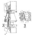
- the gas turbine engine 18 comprises substantially an axial compressor 10, a heater 11 with low pollutant emissions for the gaseous fuel, and an axial turbine unit 12 of a known type.
- the heater 11 has a frusto-conical head, immediately downstream from which the actual combustion area or main flame area is provided.
- the assembly is also surrounded by a space for cooling air, which is pressurised by the axial compressor 10 and circulates in the direction of the arrows F in figure 2 , which have directions opposite the direction of the flow of the combustion products output from the heater 11.
- a series of distributor blades 13 or blades of the first-stage distributor (which is subjected to the maximum temperatures), which are provided between an inner ring 14 and an outer ring 15 of the distributor, and are attached to a distributor-holder ring 17, and a series of rotary blades 16 of the rotor, which are optionally integral with the disc which supports them.
- the distributor blades 13 assure that the air and/or fuel which passes through the blades has/have a predetermined direction of flow, such as to assist the stabilisation of the main flame.
- a series of parallel burners can be fitted, which can create a corresponding annular series of additional flames, which are concentric relative to the central main flame.
- the cooling air is pressurised by the axial compressor 10, and cools the combustion chamber or heater 11, such that the air which enters the pre-mixing chamber is heated, and thus acts as combustion air.
- an injection device which is not illustrated in detail in the figures, supplies liquid fuel and thus creates the central or main combustion flame, whereas, by supplying additional liquid fuel, the circumferential series of burners creates in the combustion chamber 11 immediately downstream from the frusto-conical head, a corresponding annular series of additional pilot flames, which are concentric relative to the central main flame.
- the objective of the solution proposed in the present description is to limit the flame temperature peaks, following sudden variations of load, by means of appropriate control of the position of the blades 13 of the distributor with variable geometry.
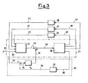
- control of the blades 13 is proposed by means of a regulation system such as that which is illustrated schematically in figure 3 .
- the system comprises a feedback branch, which is generally indicated as 20, and a direct-action branch, which is indicated as 21.
- the direct-action branch 21 comprises a calculation block 22, which implements a simplified running model of the gas turbine engine 18, complete with the actuators provided.
- the signals indicated as 23, 24, 25, and relating respectively to the combustible gas flow, the air temperature at the intake of the turbine 12, and the turbine speed 12, are input in block 22; the said signals are picked up at the output of the corresponding transducers 26, 27, 28, the inputs 29, 30, 31 of which constitute the respective signals measured directly on the gas turbine engine 18.
- a further input of the block 22 is represented by the signal 32, which represents the desired value for the temperature of the discharge gases of the turbine.
- the block 22 also supplies as output the signal 33, which represents the estimated value of the position of the distributor blades 13, required in order to obtain the desired value for the temperature of the turbine discharge gases (signal 32), with the current values 29, 30, 31 of the gas flow signals, the speed of the turbine and air temperature at the intake of the turbine, and with the flame temperature lower than a predetermined limit value.
- the control system also consists of the feedback branch 20, which consists of a proportional-integral regulator (PI regulator), which is generally indicated as 34 in figure 3 , and has at its input an error signal 35, obtained as the difference between the temperature value required at the discharge (signal 32) and the current value 38, which in fact consists of the signal 36 picked up at the output from the transducer 37.
- PI regulator proportional-integral regulator
- the output of the regulator 34 (signal 39) is then added to the signal 33 output from the measurer block 22, such as to obtain the correct estimated value (signal 40) of the position of the distributor blades 13, which is required in order to obtain the desired value for the temperature of the gases discharged from the turbine (signal 32), with the current values of flow, speed and temperature of the air (signals 29, 30, 31) and with a flame temperature lower than the limit value planned.
- the regulator 34 of the feedback branch 20 thus makes it possible to recuperate any inaccuracies of the direct-action control (branch 21), which is implemented by means of a predefined function, and according to which the position of the distributor blades 13 depends on the speed, or on a correct value of the speed, of the axial compressor 10 or of the turbine unit 12.
- the said potential inaccuracies of the direct-action branch 21 are caused by variations of the performance of the machine relative to those planned by the block 22, which constitutes the mathematical model for the gas turbine engine 18, or relative to modelling errors, and thus the presence of a further feedback branch 20 determines the possibility of making the position of the blades 13 dependent not only on the regulation of the temperature of the air admitted into, or discharged from the turbine unit 12, but also on the flow of combustible gas of the heater unit 11.
Landscapes
- Engineering & Computer Science (AREA)
- Chemical & Material Sciences (AREA)
- Combustion & Propulsion (AREA)
- Mechanical Engineering (AREA)
- General Engineering & Computer Science (AREA)
- Physics & Mathematics (AREA)
- Fluid Mechanics (AREA)
- Control Of Turbines (AREA)
- Turbine Rotor Nozzle Sealing (AREA)
- Control Of Combustion (AREA)
Applications Claiming Priority (2)
| Application Number | Priority Date | Filing Date | Title |
|---|---|---|---|
| ITMI20021231 | 2002-06-06 | ||
| IT2002MI001231A ITMI20021231A1 (it) | 2002-06-06 | 2002-06-06 | Sistema di controllo e regolazione della temperatura di fiamma per turbine a gas monoalbero |
Publications (3)
| Publication Number | Publication Date |
|---|---|
| EP1369563A2 EP1369563A2 (en) | 2003-12-10 |
| EP1369563A3 EP1369563A3 (en) | 2010-03-10 |
| EP1369563B1 true EP1369563B1 (en) | 2015-09-02 |
Family
ID=27590463
Family Applications (1)
| Application Number | Title | Priority Date | Filing Date |
|---|---|---|---|
| EP03253528.8A Expired - Lifetime EP1369563B1 (en) | 2002-06-06 | 2003-06-04 | System for control and regulation of the flame temperature for single-shaft gas turbines |
Country Status (8)
Families Citing this family (12)
| Publication number | Priority date | Publication date | Assignee | Title |
|---|---|---|---|---|
| US7280950B2 (en) * | 2004-01-22 | 2007-10-09 | Electro-Motive Diesel, Inc. | Locomotive diesel engine turbocharger and turbine stage constructed with turbine blade vibration suppression methodology |
| US7762084B2 (en) * | 2004-11-12 | 2010-07-27 | Rolls-Royce Canada, Ltd. | System and method for controlling the working line position in a gas turbine engine compressor |
| JP4952025B2 (ja) * | 2006-03-31 | 2012-06-13 | 株式会社日立製作所 | 運転制御方法,運転制御装置及び運転制御システム |
| US7762081B2 (en) * | 2007-07-25 | 2010-07-27 | Honeywell International Inc. | Compressor inlet guide vane de-ice control system and method |
| US8321119B2 (en) * | 2008-07-10 | 2012-11-27 | General Electric Company | Methods and systems to facilitate over-speed protection |
| US20100005657A1 (en) * | 2008-07-10 | 2010-01-14 | Van Vactor David R | Methods and systems to facilitate over-speed protection |
| US8224552B2 (en) * | 2008-07-10 | 2012-07-17 | General Electric Company | Methods and systems to facilitate over-speed protection |
| US9423781B2 (en) | 2013-03-29 | 2016-08-23 | General Electric Company | Model based control with engine perturbation feedback |
| EP2848370A1 (de) | 2013-09-12 | 2015-03-18 | HILTI Aktiengesellschaft | Handwerkzeugmaschine |
| JP6652853B2 (ja) * | 2016-02-12 | 2020-02-26 | 三菱日立パワーシステムズ株式会社 | ガスタービン制御装置、制御方法、プログラム |
| US10227932B2 (en) * | 2016-11-30 | 2019-03-12 | General Electric Company | Emissions modeling for gas turbine engines for selecting an actual fuel split |
| CN112432793A (zh) * | 2020-11-23 | 2021-03-02 | 东方电气集团东方汽轮机有限公司 | 一种燃气轮机轮盘抽气试验件及模化试验参数设计方法 |
Family Cites Families (33)
| Publication number | Priority date | Publication date | Assignee | Title |
|---|---|---|---|---|
| JPS5938422B2 (ja) * | 1971-10-15 | 1984-09-17 | ウエスチングハウス・エレクトリツク・コーポレーシヨン | ガスタ−ビン式パワ−・プラント |
| US4258545A (en) * | 1978-06-15 | 1981-03-31 | General Electric Company | Optimal control for a gas turbine engine |
| JPS5838328A (ja) | 1981-08-28 | 1983-03-05 | Hitachi Ltd | インレツトガイドベ−ン制御装置 |
| JPH0713472B2 (ja) * | 1985-01-25 | 1995-02-15 | 株式会社日立製作所 | タービンの運転制御方法、および複合サイクル原動機プラント |
| JPS61182425A (ja) * | 1985-02-08 | 1986-08-15 | Hitachi Ltd | ガスタ−ビン圧縮機入口案内翼の開度制御方法 |
| JPS6397835A (ja) * | 1986-10-13 | 1988-04-28 | Hitachi Ltd | ガスタ−ビン温度制御装置 |
| JPS63192919A (ja) * | 1987-02-04 | 1988-08-10 | Toshiba Corp | 石炭ガス化コンバインドプラントの制御装置 |
| GB8800904D0 (en) * | 1988-01-15 | 1988-02-17 | Rolls Royce Plc | Fuel control system |
| JPH048829A (ja) * | 1990-04-24 | 1992-01-13 | Toshiba Corp | ガスタービン制御装置 |
| JP2954754B2 (ja) * | 1991-07-22 | 1999-09-27 | 株式会社日立製作所 | ガスタービンシステムの運転制御装置及び加圧流動床ボイラ発電プラント |
| JP3040560B2 (ja) * | 1991-10-29 | 2000-05-15 | 三菱重工業株式会社 | 静翼シュラウド一体型タービン |
| US5257496A (en) * | 1992-05-05 | 1993-11-02 | General Electric Company | Combustion control for producing low NOx emissions through use of flame spectroscopy |
| JPH06241062A (ja) * | 1993-02-18 | 1994-08-30 | Hitachi Ltd | ガスタービン発電設備及びその運転方法 |
| US5394689A (en) * | 1993-09-22 | 1995-03-07 | General Electric Company | Gas turbine engine control system having integral flight Mach number synthesis method |
| JPH07281706A (ja) * | 1994-04-08 | 1995-10-27 | Mitsubishi Heavy Ind Ltd | 先行要素自動付加,除外制御装置 |
| JP3730275B2 (ja) * | 1994-07-14 | 2005-12-21 | 株式会社東芝 | ガスタービンの可変案内翼制御装置 |
| EP0740185A2 (en) * | 1995-04-26 | 1996-10-30 | Canon Kabushiki Kaisha | Liquid crystal device, image display apparatus and image forming apparatus |
| JP3733574B2 (ja) * | 1995-05-19 | 2006-01-11 | 石川島播磨重工業株式会社 | ガスタービン用可変静翼のすべり軸受 |
| JP2805600B2 (ja) * | 1995-08-07 | 1998-09-30 | 川崎重工業株式会社 | ガスタービン用ノズル回転装置 |
| JP3716018B2 (ja) * | 1995-11-02 | 2005-11-16 | 三菱重工業株式会社 | 可変入口案内翼制御方法 |
| US6071114A (en) * | 1996-06-19 | 2000-06-06 | Meggitt Avionics, Inc. | Method and apparatus for characterizing a combustion flame |
| US5896736A (en) | 1997-03-06 | 1999-04-27 | General Electric Company | Load rejection rapid acting fuel-air controller for gas turbine |
| US5931636A (en) * | 1997-08-28 | 1999-08-03 | General Electric Company | Variable area turbine nozzle |
| JPH11200890A (ja) * | 1998-01-14 | 1999-07-27 | Toshiba Corp | ガスタービン装置の空気供給装置 |
| JP3783442B2 (ja) * | 1999-01-08 | 2006-06-07 | 株式会社日立製作所 | ガスタービンの制御方法 |
| US6164057A (en) * | 1999-03-16 | 2000-12-26 | General Electric Co. | Gas turbine generator having reserve capacity controller |
| US6073445A (en) * | 1999-03-30 | 2000-06-13 | Johnson; Arthur | Methods for producing hydro-electric power |
| JP3677536B2 (ja) * | 1999-10-27 | 2005-08-03 | 株式会社日立製作所 | ガスタービン発電制御装置 |
| JP3479672B2 (ja) * | 1999-12-28 | 2003-12-15 | 川崎重工業株式会社 | ガスタービンの制御方法および制御装置 |
| JP3849071B2 (ja) * | 2000-01-18 | 2006-11-22 | 株式会社日立製作所 | ガスタービン設備の運転方法 |
| US6449953B1 (en) * | 2000-04-28 | 2002-09-17 | General Electric Company | Methods for reducing gas turbine engine emissions |
| US6408611B1 (en) * | 2000-08-10 | 2002-06-25 | Honeywell International, Inc. | Fuel control method for gas turbine |
| JP2003278561A (ja) | 2002-03-26 | 2003-10-02 | Mitsubishi Heavy Ind Ltd | 入口案内翼制御装置 |
-
2002
- 2002-06-06 IT IT2002MI001231A patent/ITMI20021231A1/it unknown
-
2003
- 2003-05-29 CA CA2430441A patent/CA2430441C/en not_active Expired - Lifetime
- 2003-06-03 US US10/452,922 patent/US7003940B2/en not_active Expired - Lifetime
- 2003-06-04 EP EP03253528.8A patent/EP1369563B1/en not_active Expired - Lifetime
- 2003-06-05 KR KR1020030036215A patent/KR100785546B1/ko not_active Expired - Fee Related
- 2003-06-05 NO NO20032557A patent/NO338996B1/no not_active IP Right Cessation
- 2003-06-06 CN CNB031476961A patent/CN1330866C/zh not_active Expired - Fee Related
- 2003-06-06 JP JP2003161427A patent/JP4895465B2/ja not_active Expired - Fee Related
Also Published As
| Publication number | Publication date |
|---|---|
| ITMI20021231A1 (it) | 2003-12-09 |
| NO20032557D0 (no) | 2003-06-05 |
| EP1369563A3 (en) | 2010-03-10 |
| KR100785546B1 (ko) | 2007-12-12 |
| CN1495351A (zh) | 2004-05-12 |
| NO20032557L (no) | 2003-12-08 |
| EP1369563A2 (en) | 2003-12-10 |
| JP4895465B2 (ja) | 2012-03-14 |
| NO338996B1 (no) | 2016-11-07 |
| CN1330866C (zh) | 2007-08-08 |
| JP2004028098A (ja) | 2004-01-29 |
| US7003940B2 (en) | 2006-02-28 |
| US20040040279A1 (en) | 2004-03-04 |
| KR20030095283A (ko) | 2003-12-18 |
| CA2430441C (en) | 2010-02-16 |
| CA2430441A1 (en) | 2003-12-06 |
Similar Documents
| Publication | Publication Date | Title |
|---|---|---|
| EP1063402B1 (en) | Method for operating an industrial gas turbine with optimal performance | |
| CN106762158B (zh) | 用于操作燃气涡轮的同时维持排放标准的系统和方法 | |
| EP1369563B1 (en) | System for control and regulation of the flame temperature for single-shaft gas turbines | |
| EP3755895B1 (en) | Controller and method | |
| JP2021193298A (ja) | ガスタービンエンジンの拡張された排出量適合動作のためのシステムおよび方法 | |
| EP3755896B1 (en) | Controller and method | |
| EP3321590A1 (en) | Auto-thermal fuel nozzle flow modulation | |
| US20170058770A1 (en) | System and method for decoupling steam production dependency from gas turbine load level | |
| CN116906188A (zh) | 燃料温度控制系统 | |
| JP3551215B2 (ja) | 蒸気注入ガスタービンとその制御方法 | |
| US20160312649A1 (en) | High performance robust gas turbine exhaust with variable (adaptive) exhaust diffuser geometry | |
| EP4232699B1 (en) | Method of controlling a combustor | |
| US12006881B2 (en) | Method of controlling a combustor |
Legal Events
| Date | Code | Title | Description |
|---|---|---|---|
| PUAI | Public reference made under article 153(3) epc to a published international application that has entered the european phase |
Free format text: ORIGINAL CODE: 0009012 |
|
| AK | Designated contracting states |
Kind code of ref document: A2 Designated state(s): AT BE BG CH CY CZ DE DK EE ES FI FR GB GR HU IE IT LI LU MC NL PT RO SE SI SK TR |
|
| AX | Request for extension of the european patent |
Extension state: AL LT LV MK |
|
| PUAL | Search report despatched |
Free format text: ORIGINAL CODE: 0009013 |
|
| AK | Designated contracting states |
Kind code of ref document: A3 Designated state(s): AT BE BG CH CY CZ DE DK EE ES FI FR GB GR HU IE IT LI LU MC NL PT RO SE SI SK TR |
|
| AX | Request for extension of the european patent |
Extension state: AL LT LV MK |
|
| 17P | Request for examination filed |
Effective date: 20100910 |
|
| AKX | Designation fees paid |
Designated state(s): CH DE FR GB IT LI NL |
|
| 17Q | First examination report despatched |
Effective date: 20101026 |
|
| REG | Reference to a national code |
Ref country code: DE Ref legal event code: R079 Ref document number: 60347983 Country of ref document: DE Free format text: PREVIOUS MAIN CLASS: F02C0009220000 Ipc: F02C0009540000 |
|
| GRAP | Despatch of communication of intention to grant a patent |
Free format text: ORIGINAL CODE: EPIDOSNIGR1 |
|
| RIC1 | Information provided on ipc code assigned before grant |
Ipc: F02C 9/54 20060101AFI20150312BHEP Ipc: F23N 5/18 20060101ALI20150312BHEP Ipc: F01D 17/16 20060101ALI20150312BHEP Ipc: F02C 9/28 20060101ALI20150312BHEP Ipc: F02C 9/22 20060101ALI20150312BHEP Ipc: F23N 5/02 20060101ALI20150312BHEP |
|
| INTG | Intention to grant announced |
Effective date: 20150409 |
|
| GRAS | Grant fee paid |
Free format text: ORIGINAL CODE: EPIDOSNIGR3 |
|
| GRAA | (expected) grant |
Free format text: ORIGINAL CODE: 0009210 |
|
| AK | Designated contracting states |
Kind code of ref document: B1 Designated state(s): CH DE FR GB IT LI NL |
|
| REG | Reference to a national code |
Ref country code: GB Ref legal event code: FG4D |
|
| REG | Reference to a national code |
Ref country code: CH Ref legal event code: EP |
|
| REG | Reference to a national code |
Ref country code: DE Ref legal event code: R096 Ref document number: 60347983 Country of ref document: DE |
|
| REG | Reference to a national code |
Ref country code: NL Ref legal event code: FP |
|
| REG | Reference to a national code |
Ref country code: DE Ref legal event code: R097 Ref document number: 60347983 Country of ref document: DE |
|
| REG | Reference to a national code |
Ref country code: FR Ref legal event code: PLFP Year of fee payment: 14 |
|
| PLBE | No opposition filed within time limit |
Free format text: ORIGINAL CODE: 0009261 |
|
| STAA | Information on the status of an ep patent application or granted ep patent |
Free format text: STATUS: NO OPPOSITION FILED WITHIN TIME LIMIT |
|
| 26N | No opposition filed |
Effective date: 20160603 |
|
| REG | Reference to a national code |
Ref country code: NL Ref legal event code: MM Effective date: 20160701 |
|
| PG25 | Lapsed in a contracting state [announced via postgrant information from national office to epo] |
Ref country code: NL Free format text: LAPSE BECAUSE OF NON-PAYMENT OF DUE FEES Effective date: 20160701 |
|
| REG | Reference to a national code |
Ref country code: FR Ref legal event code: PLFP Year of fee payment: 15 |
|
| REG | Reference to a national code |
Ref country code: FR Ref legal event code: PLFP Year of fee payment: 16 |
|
| PGFP | Annual fee paid to national office [announced via postgrant information from national office to epo] |
Ref country code: DE Payment date: 20210519 Year of fee payment: 19 Ref country code: FR Payment date: 20210519 Year of fee payment: 19 Ref country code: IT Payment date: 20210519 Year of fee payment: 19 |
|
| PGFP | Annual fee paid to national office [announced via postgrant information from national office to epo] |
Ref country code: CH Payment date: 20210520 Year of fee payment: 19 Ref country code: GB Payment date: 20210519 Year of fee payment: 19 |
|
| REG | Reference to a national code |
Ref country code: DE Ref legal event code: R119 Ref document number: 60347983 Country of ref document: DE |
|
| REG | Reference to a national code |
Ref country code: CH Ref legal event code: PL |
|
| GBPC | Gb: european patent ceased through non-payment of renewal fee |
Effective date: 20220604 |
|
| PG25 | Lapsed in a contracting state [announced via postgrant information from national office to epo] |
Ref country code: LI Free format text: LAPSE BECAUSE OF NON-PAYMENT OF DUE FEES Effective date: 20220630 Ref country code: FR Free format text: LAPSE BECAUSE OF NON-PAYMENT OF DUE FEES Effective date: 20220630 Ref country code: CH Free format text: LAPSE BECAUSE OF NON-PAYMENT OF DUE FEES Effective date: 20220630 |
|
| PG25 | Lapsed in a contracting state [announced via postgrant information from national office to epo] |
Ref country code: GB Free format text: LAPSE BECAUSE OF NON-PAYMENT OF DUE FEES Effective date: 20220604 Ref country code: DE Free format text: LAPSE BECAUSE OF NON-PAYMENT OF DUE FEES Effective date: 20230103 |
|
| PG25 | Lapsed in a contracting state [announced via postgrant information from national office to epo] |
Ref country code: IT Free format text: LAPSE BECAUSE OF NON-PAYMENT OF DUE FEES Effective date: 20220604 |