EP1366246B1 - Einer vorrichtung zur herstellung von käfigen zugeordnetes bildungselement - Google Patents
Einer vorrichtung zur herstellung von käfigen zugeordnetes bildungselement Download PDFInfo
- Publication number
- EP1366246B1 EP1366246B1 EP02710688A EP02710688A EP1366246B1 EP 1366246 B1 EP1366246 B1 EP 1366246B1 EP 02710688 A EP02710688 A EP 02710688A EP 02710688 A EP02710688 A EP 02710688A EP 1366246 B1 EP1366246 B1 EP 1366246B1
- Authority
- EP
- European Patent Office
- Prior art keywords
- frame member
- former
- transverse
- inner frame
- outer frame
- Prior art date
- Legal status (The legal status is an assumption and is not a legal conclusion. Google has not performed a legal analysis and makes no representation as to the accuracy of the status listed.)
- Expired - Lifetime
Links
Images


Classifications
-
- B—PERFORMING OPERATIONS; TRANSPORTING
- B21—MECHANICAL METAL-WORKING WITHOUT ESSENTIALLY REMOVING MATERIAL; PUNCHING METAL
- B21F—WORKING OR PROCESSING OF METAL WIRE
- B21F27/00—Making wire network, i.e. wire nets
- B21F27/12—Making special types or portions of network by methods or means specially adapted therefor
- B21F27/121—Making special types or portions of network by methods or means specially adapted therefor of tubular form, e.g. as reinforcements for pipes or pillars
- B21F27/122—Making special types or portions of network by methods or means specially adapted therefor of tubular form, e.g. as reinforcements for pipes or pillars by attaching a continuous stirrup to longitudinal wires
- B21F27/124—Making special types or portions of network by methods or means specially adapted therefor of tubular form, e.g. as reinforcements for pipes or pillars by attaching a continuous stirrup to longitudinal wires applied by rotation
-
- B—PERFORMING OPERATIONS; TRANSPORTING
- B21—MECHANICAL METAL-WORKING WITHOUT ESSENTIALLY REMOVING MATERIAL; PUNCHING METAL
- B21C—MANUFACTURE OF METAL SHEETS, WIRE, RODS, TUBES, PROFILES OR LIKE SEMI-MANUFACTURED PRODUCTS OTHERWISE THAN BY ROLLING; AUXILIARY OPERATIONS USED IN CONNECTION WITH METAL-WORKING WITHOUT ESSENTIALLY REMOVING MATERIAL
- B21C47/00—Winding-up, coiling or winding-off metal wire, metal band or other flexible metal material characterised by features relevant to metal processing only
- B21C47/28—Drums or other coil-holders
-
- B—PERFORMING OPERATIONS; TRANSPORTING
- B21—MECHANICAL METAL-WORKING WITHOUT ESSENTIALLY REMOVING MATERIAL; PUNCHING METAL
- B21F—WORKING OR PROCESSING OF METAL WIRE
- B21F27/00—Making wire network, i.e. wire nets
- B21F27/12—Making special types or portions of network by methods or means specially adapted therefor
- B21F27/121—Making special types or portions of network by methods or means specially adapted therefor of tubular form, e.g. as reinforcements for pipes or pillars
Definitions
- the present invention relates generally to a former for a cage-making machine which is adapted to hold a plurality of longitudinally extending rods and, in particular, to a former which is adapted to hold a plurality of longitudinally extending reinforcing rods.
- the invention has been developed primarily for use with cage-making machines which are adapted for use in the construction of reinforcing cages for reinforcing concrete and will be described hereinafter with reference to this application. However, it will be appreciated that the invention is not limited to this particular use.
- Some cage-making machines which are adapted for constructing reinforcing cages for reinforcing concrete utilise a former which is mounted on the machine.
- the former is adapted to hold a plurality of longitudinally extending reinforcing rods during the construction of a reinforcing cage.
- the former is adapted to hold the rods such that the rods are maintained in a particular transverse relationship with respect to each other.
- Cage-making machines which employ formers of this type are usually operated by firstly inserting a plurality of longitudinally extending reinforcing rods into the former. The rods are then progressively withdrawn from the former as a reinforcing cage is constructed. Construction of the cage typically involves winding a reinforcing bar around the withdrawn portions of the rods while simultaneously welding or otherwise attaching the bar to the rods.
- a reinforcing cage manufacturer will usually have a number of formers on-hand with each former being adapted for use in the construction of a reinforcing cage having a particular arrangement of longitudinally extending reinforcing rods. There are a number of significant disadvantages associated with formers of this type.
- a further disadvantage is that the manufacturer will often have to replace the former mounted on its cage-making machine with a different former in order to produce a cage having a different arrangement of longitudinally extending reinforcing rods.
- United States Patent No. 4,625,773 discloses a machine for fabricating a reinforcing body or cage for a concrete pipe.
- the machine includes an axially stationary main wheel, an axially mobile support wheel mounted coaxially and drivable synchronously with the main wheel, a hub received by the main wheel, and a plurality of spokes radiating from the hub to the main wheel.
- Radially adjustable guide pieces are carried by the spokes and are used for supporting longitudinal rods of the cage which are to be welded to a wire which is wound around the rods.
- the transverse locations of the longitudinal rods relative to the main wheel and the hub are able to be adjusted by repositioning the radially adjustable guide pieces relative to the spokes so that the machine can be used for fabricating different types of cages.
- a former for holding a plurality of longitudinally extending rods and for use with a cage-making machine which is used for fabricating reinforcing cages for reinforcing concrete, the former including:
- an aperture substantially extends through the outer frame member, and the inner frame member is received by the aperture in the outer frame member.
- the outer frame member is a cylinder and the aperture in the outer frame member extends longitudinally through the outer frame member.
- the inner frame member is a cylinder.
- the radial location of at least one of the rod supports between the inner frame member and the outer frame member is able to be adjusted.
- At least one of the transverse frame members extends radially between the inner frame member and the outer frame member.
- At least one of the transverse frame members is skewed relative to a radially extending position between the inner frame member and the outer frame member.
- an aperture extends through the inner frame member.
- the aperture which extends through the inner frame member may be adapted to enable an axle which has a non-circular transverse cross-section to rotatably lock with the inner frame member.
- the aperture which extends through the inner frame member may have a non-circular transverse cross-section.
- the aperture which extends through the inner frame member may have a rectangular transverse cross-section.
- the transverse frame members are removably mounted between the inner frame member and the outer frame member.
- the inner frame member and the outer frame member may each include locating formations which are adapted to locate the removable transverse frame members relative to the inner frame member and the outer frame member.
- the locating formations of the inner frame member are located opposite an inside surface of the outer frame member, and the locating formations of the outer frame member are located opposite an outer surface of the inner frame member.
- Each of the locating formations may be in the form of a groove which is adapted to receive an associated one of the transverse frame members.
- each of the locating formations may be a radial groove.
- Each of the locating formations of the outer frame member may be in the form of a locating aperture which extends through a side of the outer frame member.
- Each of the locating apertures are adapted to receive the transverse frame members.
- Each of the locating apertures may extend radially through a side of the outer frame member.
- the locating formations of the inner and outer frame members are adapted to enable at least one of the transverse frame members to be skewed relative to a radially extending position between the inner and outer frame members.
- each of the transverse frame members is in the form of a plate.
- Each of the transverse frame members may include a plurality of mounting apertures.
- the mounting apertures are preferably elongate.
- the mounting apertures are preferably adapted to enable at least one of the rod supports to be removably secured to the plate.
- the rod supports may be tubes.
- a first embodiment of a former is illustrated in Figs. 1A and 1B and is designated generally as 10.
- the former 10 is adapted to hold a plurality of longitudinally extending rods.
- the former 10 includes a frame and a plurality of rod supports 11 that are each adapted to hold an associated said longitudinally extending rod.
- the rod supports 11 are mounted to the frame such that the transverse location of the rod supports 11 can be varied relative to the frame.
- the frame includes an outer frame member 20, an inner frame member 21 and a plurality of transverse frame members 22 (note that only one is shown) extending between the outer and inner frame members 20, 21.
- the rod supports 11 are mounted to the transverse frame members 22.
- the outer frame member 20 is in the form of a cylinder having flanges 30 located at either end.
- An aperture 31 extends longitudinally through the outer frame member 20.
- a plurality of locating formations in the form of radially extending grooves 32 are evenly distributed around an inner surface of the outer frame member 20. Grooves 32 extend the length of the outer frame member 20 or, alternatively, the grooves 32 may only extend through the flanges 30. Grooves 32 are substantially parallel with respect to a longitudinal axis of the outer frame member 20.
- the inner frame member 21 is also in the form of a cylinder.
- the length of the inner frame member 21 is substantially equal to the length of the outer frame member 20.
- a plurality of locating formations in the form of radially extending grooves 42 are evenly distributed around an outer surface of the inner frame member 21.
- Grooves 42 extend the length of the inner frame member 21.
- the grooves 42 may extend through a plurality of rings which are mounted at spaced locations on the inner frame member 21.
- Grooves 42 are substantially parallel with respect to a longitudinal axis of the inner frame member 21.
- the inner frame member 21 is coaxial with the outer frame member 20.
- Aperture 31 receives the inner frame member 21 such that the inner frame member 21 is spaced from the outer frame member 20.
- Each groove 42 of the inner frame member 21 is aligned with an associated groove 32 of the outer frame member 20.
- each transverse frame member 22 is generally in the form of a rectangular plate.
- the length of each transverse frame member 22 is substantially equal to the length of the outer and inner frame members 20, 21.
- the width of each transverse frame member 22 is such that the transverse frame members 22 can be mounted between the outer and inner frame members 20, 21.
- Each transverse frame member 22 includes a plurality of mounting apertures 50 extending therethrough. The mounting apertures 50 are arranged into three main banks 51 to 53 with each main bank 51 to 53 being formed from two minor banks 54 and 55 which are offset from one another.
- each rod support 11 is adapted to slidably receive a longitudinally extending rod.
- Each rod support 11 includes a tube 60 and a plurality of lugs 61 extending perpendicularly therefrom. Lugs 61 are aligned with each other and are spaced along the length of the tube 60.
- a threaded aperture extends into each lug 61 from a free end thereof. The threaded apertures enable a bolt to be screwed into each lug 61.
- the distance between each adjacent pair of lugs 61 is equal to the distance between an associated pair of adjacent and like minor banks (i.e. minor bank 54 or 55).
- each lug 61 can be received by a mounting aperture 50.
- a rod support 11 is mounted to a transverse frame member 22 by inserting each lug 61 into an associated mounting aperture 50 of each main bank 51 to 53. Once the lugs 61 are inserted into the transverse frame member 22, the rod support 11 is secured to the transverse frame member 22 by screwing a bolt into the threaded aperture of each lug 61.
- the mounting location of the rod supports 11 on the transverse frame member 22 can be varied by choosing different mounting apertures 50.
- a single transverse frame member 22 having a plurality of rod supports 11 mounted thereto is shown removably mounted between the outer and inner frame members 20, 21.
- the rod supports 11 are mounted to the transverse frame member 22 such that they are substantially parallel to a longitudinal axis of both the outer and inner frame members 20, 21. Further, the rod supports 11 are located on either side of the transverse frame member 22 such that the rod supports 11 on one side of the transverse frame member 22 are offset from the rod supports 11 on the opposite side of the transverse frame member 22.
- the transverse frame member 22 is mounted between the outer and inner frame members 20, 21 by aligning each longitudinal edge of the transverse frame member 22 with an associated groove 32 or 42 and then sliding the transverse frame member 22 between the outer and inner frame members 20, 21.
- Each groove 32, 42 is adapted to receive a longitudinal edge of the transverse frame member 22 such that the transverse frame member 22 is positively located relative to the outer and inner frame members 20, 21.
- the transverse frame member 22 is able to be mounted such that it extends radially between the outer and inner frame members 20, 21. In this case the longitudinal edges of the transverse frame member 22 are received by aligned grooves 32,42.
- Fig. 1 A only shows a single transverse frame member 22, a plurality of transverse frame members 22 will normally be mounted between the outer and inner frame members 20, 21.
- the transverse frame members 22 typically support the inner frame member 21 within the outer frame member 20.
- the inner frame member 21 may be supported within the outer frame member 20 by some other means so that the inner frame member 21 maintains its position relative to the outer frame member 20 even if all of the transverse frame members 22 are removed from between the outer and inner frame members 20, 21.
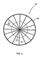
- Fig. 4 illustrates the former 10 when a plurality of transverse frame members 22 are mounted between the outer and inner frame members 20, 21.
- the transverse frame members 22 extend radially between the outer and inner frame members 20, 21.
- the former 10 is shown having four transverse frame members 22 mounted between the outer and inner frame members 20, 21.
- each groove 32 of the outer frame member 20 is aligned with an associated groove 42 of the inner frame member 21.
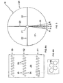
- grooves 32, 42 are adapted so that the transverse frame members 22 can be mounted in grooves 32, 42 which are not aligned with each other. This enables the transverse frame members 22 to be mounted such that they do not extend radially between the outer and inner frame members 20, 21 and are slightly skewed.
- the inclination of the transverse frame members 22 relative to the outer and inner frame members 20, 21 can be varied.
- grooves 32, 42 may be adapted to enable the transverse frame members 22 to be mounted between the outer and inner frame members 20, 21 in any one of the illustrated positions A, B, C, D or E.
- Figs. 6A and 6B further illustrate the transverse frame member 22 used in the former 10.
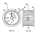
- FIG. 7A and 7B A second embodiment of a former is illustrated in Figs. 7A and 7B and is designated generally as 100.
- features of the former 100 that are similar or correspond to features of the former 10 have been referenced using the same reference numbers.
- the outer frame member 20 is generally in the form of a cylinder having flanges 30 located at either end.
- the cylinder is constructed from a plurality of longitudinally extending elongated members 101, wherein each elongated member 101 has a substantially rectangular transverse cross-section.
- Flanges 30 are provided by a pair of axially aligned rings that are spaced apart from each other.
- Each elongated member 101 extends between the rings and is suitably mounted to an inner surface of each ring.
- the elongated members 101 are mounted to the rings such that adjacent elongated members 101 are separated from each other by radial locating apertures 102 which function as locating formations.
- the locating apertures 102 which are identical to each other, extend the length of the outer frame member 20 and are substantially parallel with respect to a longitudinal axis of the outer frame member 20.
- the locating apertures 102 are evenly distributed around the perimeter of the outer frame member 20 and each locating aperture 102 is aligned with an associated groove 42 of the inner frame member 21.
- transverse frame members 22 can be mounted between the outer and inner frame members 20, 21 of the former 100.
- the first method is identical to the method described in connection with the former 10.
- a transverse frame member 22 is inserted through an associated locating aperture 102 so that a longitudinal edge of the transverse frame member 22 is received by an associated groove 42 and an opposite longitudinal edge is received by an associated locating aperture 102.
- This second method is illustrated in Fig. 7A which shows three different transverse frame members 22 at various stages of insertion between the outer and inner frame members 20, 21.
- the rod supports 11 must be removed from the transverse frame members 22 before the transverse frame members 22 are able to pass through the locating apertures 102.
- the transverse frame members 22 need to be secured to the outer or inner frame members 20, 21 by a suitable means to prevent them from falling out of the former 100.
- Grooves 42 and locating apertures 102 can be configured so that the inclination of the transverse frame members 22 relative to the outer and inner frame members 20, 21 can be varied.
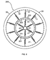
- FIG. 8 A third embodiment of a former is illustrated in Fig. 8 and is designated generally as 200.
- features of the former 200 that are similar or correspond to features of the previously described embodiments have been referenced using the same reference numbers.
- Former 200 is similar to former 10 except that former 200 includes an intermediate frame member 201. Also, transverse frame members 22 extend between the intermediate and inner frame members 201, 21. Further, transverse frame members 22 extend between the intermediate and outer frame members 201, 20.
- the intermediate frame member 201 has a similar configuration to the outer frame member 20 except that the intermediate frame member 201 has a plurality of locating formations in the form of radial grooves 202, 203 which are evenly distributed around an outer and inner surface, respectively, of the intermediate frame member 201. Grooves 202, 203 extend the length of the intermediate frame member 201 and are substantially parallel with respect to a longitudinal axis of the intermediate frame member 201. Each groove 202 of the intermediate frame member 201 is aligned with an associated groove 32 of the outer frame member 20. Also, each groove 203 of the intermediate frame member 201 is aligned with an associated groove 42 of the inner frame member 21.
- FIG. 9A and 9B A fourth embodiment of a former is illustrated in Figs. 9A and 9B and is designated generally as 300.
- the former 300 that are similar or correspond to features of the previously described embodiments have been referenced using the same reference numbers.
- Former 300 is similar to former 10 except that former 300 includes an aperture 301 which extends through the inner frame member 21.
- the aperture 301 is adapted to enable an axle having a non-circular transverse cross-section to rotatably lock with the inner frame member 21.
- the aperture 301 has a rectangular transverse cross-section.
- Fig. 10 illustrates the configuration of the transverse frame members 22 which are used in the former 300.
- FIG. 11A and 11B A fifth embodiment of a former is illustrated in Figs. 11A and 11B and is designated generally as 400.
- the former 400 that are similar or correspond to features of the previously described embodiments have been referenced using the same reference numbers.
- Former 400 is similar to former 300 except that former 400 uses transverse frame members 401 which have a different configuration to the transverse frame members 22 used by former 300.
- Each transverse frame member 401 is generally in the form of a rectangular plate.
- the length of each transverse frame member 401 is substantially equal to the length of the outer and inner frame members 20, 21.
- the width of each transverse frame member 401 is substantially equal to the width of the gap between the outer and inner frame members 20, 21.
- Each transverse frame member 401 includes a plurality of elongated mounting apertures 402, 403 extending therethrough.
- the mounting apertures 402, 403 are arranged into three banks 404 to 406 with each bank 404 to 406 being formed from a pair of parallel mounting apertures 402, 403 which are offset from one another.
- the rod support 11 illustrated in Figs. 13A and 13B is identical to the rod support 11 illustrated in Figs. 3A and 3B.
- the distance between each pair of adjacent lugs 61 is equal to the distance between an associated pair of adjacent and like mounting apertures 402, 403.
- Rod support 11 is mounted to the transverse frame member 401 by inserting each lug 61 into an associated mounting aperture 402 or 403. Once the lugs 61 are inserted into the transverse frame member 401, the rod support 11 is secured to the transverse frame member 401 by screwing a bolt into the threaded aperture of each lug 61.
- the location of the rod support 11 relative to the transverse frame member 401 can be varied by sliding the lugs 61 within the apertures 402, 403. This change of location can be implemented manually or by a suitable mechanical means.
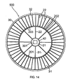
- a sixth embodiment of a former is illustrated in Fig. 14 and is designated generally as 500.
- features of the former 500 that are similar or correspond to features of the previously described embodiments have been referenced using the same reference numbers.
- Former 500 is similar to former 200 except that the inner frame member 21 of former 500 includes an aperture 301 in a similar manner to formers 300 and 400.
Landscapes
- Engineering & Computer Science (AREA)
- Mechanical Engineering (AREA)
- Tyre Moulding (AREA)
- Soil Working Implements (AREA)
- Moulds, Cores, Or Mandrels (AREA)
- Moulds For Moulding Plastics Or The Like (AREA)
- Preparation Of Compounds By Using Micro-Organisms (AREA)
- Telephone Function (AREA)
- Medicines Containing Material From Animals Or Micro-Organisms (AREA)
- Reinforcement Elements For Buildings (AREA)
- Piles And Underground Anchors (AREA)
Claims (24)
- Formbildner (10) zur Halterung einer Vielzahl von längserstreckten Stäben und zur Verwendung mit einer Vorrichtung zur Herstellung von Käfigen, die zur Produktion von Verstärkungskäfigen für Stahlbeton eingesetzt wird, enthaltend:einen inneren Rahmenteil (21);einen äußeren Rahmenteil (20);eine Vielzahl von Querrahmenteilen (22), die um den Umfang des inneren Rahmenteiles (21) herum angeordnet sind und sich zwischen dem inneren Rahmenteil (21) und dem äußeren Rahmenteil (20) erstrecken; undeine Vielzahl von Stabauflagern (11) zur Halterung der Stäbe, wobei die Stabauflager (11) relativ gegenüber den Querrahmenteilen (22) gesichert sind, und wobei die Querposition wenigstens eines Stabauflagers (11) relativ gegenüber dem zugehörigen Querrahmenteil (22), an welches das besagte Stabauflager (11) angeschlossen ist, in Querrichtung verstellbar ist,dadurch gekennzeichnet, dass sich die Querposition wenigstens eines der Querrahmenteile (22) relativ im Vergleich zum inneren Rahmenteil (21) und äußeren Rahmenteil (20) verstellen lässt, so dass sich das wenigstens eine Querrahmenteil (22) radial von einer bestimmten Position auf dem Umfang des inneren Rahmenteiles (21) in Richtung auf eine Vielzahl von Positionen auf dem äußeren Rahmenteil (22) radial verschwenken lässt.
- Formbildner (10) nach Anspruch 1, dadurch gekennzeichnet, dass sich eine Öffnung (31) im Wesentlichen durch das äußere Rahmenteil (20) erstreckt, wobei das innere Rahmenteil (21) mit Hilfe der Öffnung (31) in dem äußeren Rahmenteil (20) aufgenommen wird.
- Formbildner (10) nach Anspruch 2, dadurch gekennzeichnet, dass das äußere Rahmenteil (20) zylindrisch ausgebildet ist und sich die Öffnung (31) im Rahmenteil (20) längs durch das äußere Rahmenteil (20) erstreckt.
- Formbildner (10) nach Anspruch 1, dadurch gekennzeichnet, dass es sich bei dem inneren Rahmenteil (21) um einen Zylinder handelt.
- Formbildner (10) nach Anspruch 1, dadurch gekennzeichnet, dass sich die radiale Position wenigstens eines der Stabauflager (11) zwischen dem inneren Rahmenteil (21) und dem äußeren Rahmenteil (20) verstellen lässt.
- Formbildner (10) nach Anspruch 1, dadurch gekennzeichnet, dass sich wenigstens eines der Querrahmenteile (22) radial zwischen dem inneren Rahmenteil (21) und dem äußeren Rahmenteil (20) erstreckt.
- Formbildner (10) nach Anspruch 1, dadurch gekennzeichnet, dass wenigstens eines der Querrahmenteile (22) im Vergleich zu einer Position in radialer Richtung zwischen dem inneren Rahmenteil (21) und dem äußeren Rahmenteil (20) abgeschrägt ist.
- Formbildner (10) nach Anspruch 1, dadurch gekennzeichnet, dass sich eine Öffnung (301) durch das innere Rahmenteil (21) erstreckt.
- Formbildner (10) nach Anspruch 8, dadurch gekennzeichnet, dass die sich durch das innere Rahmenteil (21) erstreckende Öffnung (301) zur Rotationsfesselung einer Achse nicht kreisförmigen Querschnittes zur Verbindung mit dem inneren Rahmenteil (21) ausgebildet ist.
- Formbildner (10) nach Anspruch 9, dadurch gekennzeichnet, dass die sich durch den inneren Rahmenteil (21) erstreckende Öffnung (301) einen nicht kreisförmigen Querschnitt aufweist.
- Formbildner (10) nach Anspruch 10, dadurch gekennzeichnet, dass die sich durch den inneren Rahmenteil (21) erstreckende Öffnung (301) einen rechteckförmigen Querschnitt aufweist.
- Formbildner (10) nach Anspruch 1, dadurch gekennzeichnet, dass die Querrahmenteile (22) entfernbar zwischen dem inneren Rahmenteil (21) und dem äußeren Rahmenteil (20) befestigt sind.
- Formbildner (10) nach Anspruch 12, dadurch gekennzeichnet, dass sowohl der innere Rahmenteil (21) als auch der äußere Rahmenteil (20) Ortsfixierungen (32, 42) aufweisen, welche zur Festlegung der relativ im Vergleich zu dem inneren Rahmenteil (21) und dem äußeren Rahmenteil (20) entfernbaren Querrahmenteile (22) dienen.
- Formbildner (10) nach Anspruch 13, dadurch gekennzeichnet, dass die Ortsfixierungen (42) des inneren Rahmenteiles (21) einer Innenoberfläche des äußeren Rahmenteiles (20) gegenüberliegend angeordnet sind und die Ortsfixierungen (32) des äußeren Rahmenteiles (20) einer äußeren Oberfläche des inneren Rahmenteiles (21) gegenüberliegen.
- Formbildner (10) nach Anspruch 14, dadurch gekennzeichnet, dass die Ortsfixierungen (32, 42) jeweils als Nut ausgebildet sind, welche zur Aufnahme eines zugehörigen Gegenstückes des Querrahmenteiles (22) eingerichtet ist.
- Formbildner (10) nach Anspruch 15, dadurch gekennzeichnet, dass es sich bei den Ortsfixierungen (32, 42) jeweils um eine Radialnut handelt.
- Formbildner (10) nach Anspruch 13, dadurch gekennzeichnet, dass jede Ortsfixierung (42) des inneren Rahmenteils (21) eine Nut darstellt, welche geeignet ist, ein zugehöriges Gegenstück des Querrahmenteiles (22) aufzunehmen und jede der Ortsfixierungen (32) des äußeren Rahmenteiles (20) als Fixierungsöffnung ausgebildet ist, welche sich durch eine Seite des äußeren Rahmenteiles (20) erstreckt, wobei die Ortsfixierungen (32) eingerichtet sind, um die Querrahmenteile (22) aufzunehmen.
- Formbildner (10) nach Anspruch 17, dadurch gekennzeichnet, dass sich jede der Ortsfixierungen (32, 42) radial durch eine Seite des äußeren Rahmenteiles (20) erstreckt und jede der Ortsfixierungen (32, 42) des inneren Rahmenteiles (21) als Radialnut ausgebildet ist.
- Formbildner (10) nach Anspruch 1, dadurch gekennzeichnet, dass jedes der Querrahmenteile (22) als Platte ausgebildet ist.
- Formbildner (10) nach Anspruch 19, dadurch gekennzeichnet, dass jedes der Querrahmenteile (22) eine Vielzahl von Montageöffnungen (50) aufweist.
- Formbildner (10) nach Anspruch 20, dadurch gekennzeichnet, dass die Montageöffnungen (50) längserstreckt ausgebildet sind.
- Formbildner (10) nach Anspruch 20, dadurch gekennzeichnet, dass die Montageöffnungen (50) so ausgebildet sind, dass sie wenigstens eine der Stabauflager (11) entfernbar gesichert im Vergleich zu der Platte aufnehmen.
- Formbildner (10) nach Anspruch 1, dadurch gekennzeichnet, dass es sich bei den Stabauflagern (11) um Rohre handelt.
- Formbildner (10) nach Anspruch 23, dadurch gekennzeichnet, dass sich eine Vielzahl von Ansätzen (61) von jedem Stabauflager (11) ausgehend erstrecken, wobei die Ansätze (61) so eingerichtet sind, dass sie von den Querrahmenteilen (22) aufgenommen werden.
Applications Claiming Priority (3)
| Application Number | Priority Date | Filing Date | Title |
|---|---|---|---|
| AUPR3003A AUPR300301A0 (en) | 2001-02-09 | 2001-02-09 | A former associated with an apparatus for making cages |
| AUPR300301 | 2001-02-09 | ||
| PCT/AU2002/000124 WO2002064906A1 (en) | 2001-02-09 | 2002-02-08 | A former associated with an apparatus for making cages |
Publications (3)
| Publication Number | Publication Date |
|---|---|
| EP1366246A1 EP1366246A1 (de) | 2003-12-03 |
| EP1366246A4 EP1366246A4 (de) | 2005-03-16 |
| EP1366246B1 true EP1366246B1 (de) | 2007-04-11 |
Family
ID=3827026
Family Applications (1)
| Application Number | Title | Priority Date | Filing Date |
|---|---|---|---|
| EP02710688A Expired - Lifetime EP1366246B1 (de) | 2001-02-09 | 2002-02-08 | Einer vorrichtung zur herstellung von käfigen zugeordnetes bildungselement |
Country Status (7)
| Country | Link |
|---|---|
| US (1) | US7124785B2 (de) |
| EP (1) | EP1366246B1 (de) |
| AT (1) | ATE359414T1 (de) |
| AU (1) | AUPR300301A0 (de) |
| DE (1) | DE60219440T2 (de) |
| ES (1) | ES2286235T3 (de) |
| WO (1) | WO2002064906A1 (de) |
Cited By (1)
| Publication number | Priority date | Publication date | Assignee | Title |
|---|---|---|---|---|
| CN106938309A (zh) * | 2017-05-18 | 2017-07-11 | 荆门创佳机械科技有限公司 | 一种加工圆形钢筋笼的支撑装置 |
Families Citing this family (6)
| Publication number | Priority date | Publication date | Assignee | Title |
|---|---|---|---|---|
| NL1026278C2 (nl) | 2004-05-27 | 2005-11-30 | Steven Edward Kelly | Opbouwelement, basiselement, vasthoudmiddel en hulpmiddel voor het vervaardigen van een wapening, werkwijze voor het opbouwen van zo een hulpmiddel en werkwijze voor het vervaardigen van een wapening. |
| US20080257445A1 (en) * | 2007-04-20 | 2008-10-23 | Claudio Subacchi | Method And System For Manufacture Of A Wire Cage |
| ITBO20080118A1 (it) * | 2008-02-21 | 2009-08-22 | Gricor Impianti S R L | Dispositivo di supporto delle barre in macchine per realizzare gabbie metalliche |
| US8533956B2 (en) * | 2009-11-25 | 2013-09-17 | Jack Perry | Rebar installation system and method of securing rebar |
| US10654091B2 (en) | 2016-08-02 | 2020-05-19 | Dimension Fabricators, Inc. | Rebar cage assembly apparatus |
| CN106988301B (zh) * | 2017-05-21 | 2019-01-04 | 荆门创佳机械科技有限公司 | 一种加工圆形钢筋笼的中间支撑装置 |
Family Cites Families (17)
| Publication number | Priority date | Publication date | Assignee | Title |
|---|---|---|---|---|
| US1488340A (en) * | 1917-10-22 | 1924-03-25 | Andrew G Gustafson | Wheel |
| US1411382A (en) * | 1920-05-28 | 1922-04-04 | Central Wheel Company | Wire wheel |
| AU439402B2 (en) | 1969-06-18 | 1973-08-17 | Nippon Evola Pipes Co., Ltd | Apparatus for making a double-layer reinforcing cage for concrete pipes |
| US3579259A (en) * | 1969-06-23 | 1971-05-18 | Nippon Rocla Pipes Co Ltd | Apparatus for making a double-layer reinforcing cage for concrete pipes |
| DE2360532A1 (de) | 1973-12-05 | 1975-06-12 | Georg Pfender | Maschine zur herstellung von bewehrungskoerpern fuer betonrohre |
| IT1141782B (it) | 1980-03-05 | 1986-10-08 | Rema Macchine Utensili Spa | Macchina formatrice di gabbie |
| DE3422420A1 (de) * | 1984-06-16 | 1985-12-19 | Mbk Maschinenbau Gmbh, 7964 Kisslegg | Maschine zur herstellung von bewehrungskoerpern fuer betonrohre |
| DE3511824A1 (de) * | 1985-03-30 | 1986-10-09 | Hubert 7965 Ostrach Keller | Verfahren und vorrichtung zur herstellung eines armierungskorbes fuer stahlbetonbauteile |
| CA2043658C (en) * | 1990-06-07 | 1997-12-23 | Shinji Kubo | Polyester for electrophotography |
| ES2082249T3 (es) * | 1992-03-07 | 1996-03-16 | Mbk Maschinenbau Gmbh | Maquina y procedimiento para fabricar jaulas de refuerzo para tubos de hormigon. |
| DE19534450A1 (de) * | 1995-09-16 | 1997-03-20 | Sel Alcatel Ag | Videotelephoneinrichtung |
| GB2310875B (en) | 1996-03-09 | 2000-02-09 | Gray Eng Ltd | Support structure for a cage for reinforcing a concrete pile |
| DE19814091A1 (de) * | 1998-03-30 | 1999-10-07 | Mbk Maschinenbau Gmbh | Vorrichtung zur Herstellung von Bewehrungskörben für Rechteckrohre aus Beton |
| EP0955423A3 (de) | 1998-05-02 | 2000-05-31 | Rom Limited | Element um einen Betonverstärkungskäfig zu bilden |
| AUPP758898A0 (en) * | 1998-12-10 | 1999-01-07 | Barden, Wayne | An apparatus for making reinforcing cages for reinforcing concrete |
| AU722830B2 (en) | 1998-12-10 | 2000-08-10 | Wayne Barden | An apparatus for making reinforcing cages for reinforcing concrete |
| GB9901746D0 (en) | 1999-01-27 | 1999-03-17 | Rom Limited | Cage former and clamp therefor |
-
2001
- 2001-02-09 AU AUPR3003A patent/AUPR300301A0/en not_active Abandoned
-
2002
- 2002-02-08 EP EP02710688A patent/EP1366246B1/de not_active Expired - Lifetime
- 2002-02-08 WO PCT/AU2002/000124 patent/WO2002064906A1/en not_active Ceased
- 2002-02-08 ES ES02710688T patent/ES2286235T3/es not_active Expired - Lifetime
- 2002-02-08 US US10/470,270 patent/US7124785B2/en not_active Expired - Lifetime
- 2002-02-08 AT AT02710688T patent/ATE359414T1/de not_active IP Right Cessation
- 2002-02-08 DE DE60219440T patent/DE60219440T2/de not_active Expired - Lifetime
Cited By (1)
| Publication number | Priority date | Publication date | Assignee | Title |
|---|---|---|---|---|
| CN106938309A (zh) * | 2017-05-18 | 2017-07-11 | 荆门创佳机械科技有限公司 | 一种加工圆形钢筋笼的支撑装置 |
Also Published As
| Publication number | Publication date |
|---|---|
| WO2002064906A1 (en) | 2002-08-22 |
| EP1366246A4 (de) | 2005-03-16 |
| ES2286235T3 (es) | 2007-12-01 |
| EP1366246A1 (de) | 2003-12-03 |
| DE60219440T2 (de) | 2008-01-03 |
| US7124785B2 (en) | 2006-10-24 |
| DE60219440D1 (de) | 2007-05-24 |
| ATE359414T1 (de) | 2007-05-15 |
| AUPR300301A0 (en) | 2001-03-08 |
| US20040099330A1 (en) | 2004-05-27 |
Similar Documents
| Publication | Publication Date | Title |
|---|---|---|
| EP1366246B1 (de) | Einer vorrichtung zur herstellung von käfigen zugeordnetes bildungselement | |
| US6997330B2 (en) | Apparatus and method for storing or shipping elongated members | |
| US6901717B2 (en) | Pole reinforcing arrangement | |
| KR101188067B1 (ko) | 철근케이지의 제조 장치 | |
| WO2013055814A1 (en) | Truss system with integral channels | |
| CA2718022A1 (en) | Reel assemblies with customizable and interchangeable drums | |
| EP2265397B1 (de) | Stützvorrichtung für stangen in maschinen zur herstellung von metallkäfigen; verwendung der vorrichtung | |
| US11975924B2 (en) | Conveyor pulley apparatus, systems, and methods | |
| AU2002229408B2 (en) | A former associated with an apparatus for making cages | |
| US20100018274A1 (en) | Anti-bending profiling head and profiling machine fitted with such heads | |
| AU2002229408A1 (en) | A former associated with an apparatus for making cages | |
| US20040178301A1 (en) | Adjustable conduit reel and removable divider | |
| EP2475478B1 (de) | Verfahren und vorrichtung zum stützen von längsstäben bei der herstellung von bewehrungselementen | |
| CN214934781U (zh) | 一种便于调节的组装式电缆放线架 | |
| JP6250215B1 (ja) | 既設配管の更新方法 | |
| CN1322187C (zh) | 纺纱机 | |
| US20240302103A1 (en) | Fixing device for reinforcing the joint of a rotary heat exchanger | |
| JP2011011792A (ja) | 帯状部材結束体および帯状部材結束体の製造方法 | |
| CN219390672U (zh) | 用于支撑换热器的中心管的支撑机构 | |
| JP6250216B1 (ja) | 新設配管、パネル部材、および既設配管の更新方法 | |
| JPH10280402A (ja) | 場所打ちコンクリート杭の鉄筋かご | |
| KR101978947B1 (ko) | 앤드리스 컨베어 벨트 감는 장치 및 그를 이용한 앤드리스 컨베어 벨트 감는 방법 | |
| JPS5855933Y2 (ja) | 理化学実験用支持枠組立体 | |
| EP3563721A1 (de) | Aufbewahrungsmöbel | |
| US2055179A (en) | Reel and method of forming it |
Legal Events
| Date | Code | Title | Description |
|---|---|---|---|
| PUAI | Public reference made under article 153(3) epc to a published international application that has entered the european phase |
Free format text: ORIGINAL CODE: 0009012 |
|
| 17P | Request for examination filed |
Effective date: 20030909 |
|
| AK | Designated contracting states |
Kind code of ref document: A1 Designated state(s): AT BE CH CY DE DK ES FI FR GB GR IE IT LI LU MC NL PT SE TR |
|
| AX | Request for extension of the european patent |
Extension state: AL LT LV MK RO SI |
|
| A4 | Supplementary search report drawn up and despatched |
Effective date: 20050202 |
|
| RIC1 | Information provided on ipc code assigned before grant |
Ipc: 7B 21D 7/04 B Ipc: 7E 04C 5/06 A Ipc: 7B 21F 27/12 B Ipc: 7B 25B 11/02 B |
|
| GRAP | Despatch of communication of intention to grant a patent |
Free format text: ORIGINAL CODE: EPIDOSNIGR1 |
|
| GRAS | Grant fee paid |
Free format text: ORIGINAL CODE: EPIDOSNIGR3 |
|
| GRAA | (expected) grant |
Free format text: ORIGINAL CODE: 0009210 |
|
| AK | Designated contracting states |
Kind code of ref document: B1 Designated state(s): AT BE CH CY DE DK ES FI FR GB GR IE IT LI LU MC NL PT SE TR |
|
| PG25 | Lapsed in a contracting state [announced via postgrant information from national office to epo] |
Ref country code: LI Free format text: LAPSE BECAUSE OF FAILURE TO SUBMIT A TRANSLATION OF THE DESCRIPTION OR TO PAY THE FEE WITHIN THE PRESCRIBED TIME-LIMIT Effective date: 20070411 Ref country code: CH Free format text: LAPSE BECAUSE OF FAILURE TO SUBMIT A TRANSLATION OF THE DESCRIPTION OR TO PAY THE FEE WITHIN THE PRESCRIBED TIME-LIMIT Effective date: 20070411 Ref country code: FI Free format text: LAPSE BECAUSE OF FAILURE TO SUBMIT A TRANSLATION OF THE DESCRIPTION OR TO PAY THE FEE WITHIN THE PRESCRIBED TIME-LIMIT Effective date: 20070411 |
|
| REG | Reference to a national code |
Ref country code: GB Ref legal event code: FG4D |
|
| REG | Reference to a national code |
Ref country code: CH Ref legal event code: EP |
|
| REG | Reference to a national code |
Ref country code: IE Ref legal event code: FG4D |
|
| REF | Corresponds to: |
Ref document number: 60219440 Country of ref document: DE Date of ref document: 20070524 Kind code of ref document: P |
|
| PG25 | Lapsed in a contracting state [announced via postgrant information from national office to epo] |
Ref country code: SE Free format text: LAPSE BECAUSE OF FAILURE TO SUBMIT A TRANSLATION OF THE DESCRIPTION OR TO PAY THE FEE WITHIN THE PRESCRIBED TIME-LIMIT Effective date: 20070711 |
|
| PG25 | Lapsed in a contracting state [announced via postgrant information from national office to epo] |
Ref country code: PT Free format text: LAPSE BECAUSE OF FAILURE TO SUBMIT A TRANSLATION OF THE DESCRIPTION OR TO PAY THE FEE WITHIN THE PRESCRIBED TIME-LIMIT Effective date: 20070911 |
|
| NLV1 | Nl: lapsed or annulled due to failure to fulfill the requirements of art. 29p and 29m of the patents act | ||
| ET | Fr: translation filed | ||
| REG | Reference to a national code |
Ref country code: CH Ref legal event code: PL |
|
| PG25 | Lapsed in a contracting state [announced via postgrant information from national office to epo] |
Ref country code: AT Free format text: LAPSE BECAUSE OF FAILURE TO SUBMIT A TRANSLATION OF THE DESCRIPTION OR TO PAY THE FEE WITHIN THE PRESCRIBED TIME-LIMIT Effective date: 20070411 |
|
| REG | Reference to a national code |
Ref country code: ES Ref legal event code: FG2A Ref document number: 2286235 Country of ref document: ES Kind code of ref document: T3 |
|
| PG25 | Lapsed in a contracting state [announced via postgrant information from national office to epo] |
Ref country code: NL Free format text: LAPSE BECAUSE OF FAILURE TO SUBMIT A TRANSLATION OF THE DESCRIPTION OR TO PAY THE FEE WITHIN THE PRESCRIBED TIME-LIMIT Effective date: 20070411 Ref country code: DK Free format text: LAPSE BECAUSE OF FAILURE TO SUBMIT A TRANSLATION OF THE DESCRIPTION OR TO PAY THE FEE WITHIN THE PRESCRIBED TIME-LIMIT Effective date: 20070411 |
|
| PLBE | No opposition filed within time limit |
Free format text: ORIGINAL CODE: 0009261 |
|
| STAA | Information on the status of an ep patent application or granted ep patent |
Free format text: STATUS: NO OPPOSITION FILED WITHIN TIME LIMIT |
|
| 26N | No opposition filed |
Effective date: 20080114 |
|
| PG25 | Lapsed in a contracting state [announced via postgrant information from national office to epo] |
Ref country code: GR Free format text: LAPSE BECAUSE OF FAILURE TO SUBMIT A TRANSLATION OF THE DESCRIPTION OR TO PAY THE FEE WITHIN THE PRESCRIBED TIME-LIMIT Effective date: 20070712 |
|
| PG25 | Lapsed in a contracting state [announced via postgrant information from national office to epo] |
Ref country code: MC Free format text: LAPSE BECAUSE OF NON-PAYMENT OF DUE FEES Effective date: 20080228 |
|
| PG25 | Lapsed in a contracting state [announced via postgrant information from national office to epo] |
Ref country code: CY Free format text: LAPSE BECAUSE OF FAILURE TO SUBMIT A TRANSLATION OF THE DESCRIPTION OR TO PAY THE FEE WITHIN THE PRESCRIBED TIME-LIMIT Effective date: 20070411 |
|
| PG25 | Lapsed in a contracting state [announced via postgrant information from national office to epo] |
Ref country code: LU Free format text: LAPSE BECAUSE OF NON-PAYMENT OF DUE FEES Effective date: 20080208 |
|
| PG25 | Lapsed in a contracting state [announced via postgrant information from national office to epo] |
Ref country code: TR Free format text: LAPSE BECAUSE OF FAILURE TO SUBMIT A TRANSLATION OF THE DESCRIPTION OR TO PAY THE FEE WITHIN THE PRESCRIBED TIME-LIMIT Effective date: 20070411 |
|
| REG | Reference to a national code |
Ref country code: FR Ref legal event code: PLFP Year of fee payment: 15 |
|
| REG | Reference to a national code |
Ref country code: FR Ref legal event code: PLFP Year of fee payment: 16 |
|
| PGFP | Annual fee paid to national office [announced via postgrant information from national office to epo] |
Ref country code: FR Payment date: 20170220 Year of fee payment: 16 |
|
| PGFP | Annual fee paid to national office [announced via postgrant information from national office to epo] |
Ref country code: BE Payment date: 20170221 Year of fee payment: 16 Ref country code: IE Payment date: 20170221 Year of fee payment: 16 |
|
| REG | Reference to a national code |
Ref country code: BE Ref legal event code: MM Effective date: 20180228 |
|
| REG | Reference to a national code |
Ref country code: FR Ref legal event code: ST Effective date: 20181031 |
|
| REG | Reference to a national code |
Ref country code: IE Ref legal event code: MM4A |
|
| PG25 | Lapsed in a contracting state [announced via postgrant information from national office to epo] |
Ref country code: IE Free format text: LAPSE BECAUSE OF NON-PAYMENT OF DUE FEES Effective date: 20180208 |
|
| PG25 | Lapsed in a contracting state [announced via postgrant information from national office to epo] |
Ref country code: BE Free format text: LAPSE BECAUSE OF NON-PAYMENT OF DUE FEES Effective date: 20180228 Ref country code: FR Free format text: LAPSE BECAUSE OF NON-PAYMENT OF DUE FEES Effective date: 20180228 |
|
| PGFP | Annual fee paid to national office [announced via postgrant information from national office to epo] |
Ref country code: DE Payment date: 20210126 Year of fee payment: 20 Ref country code: GB Payment date: 20210127 Year of fee payment: 20 Ref country code: ES Payment date: 20210308 Year of fee payment: 20 |
|
| PGFP | Annual fee paid to national office [announced via postgrant information from national office to epo] |
Ref country code: IT Payment date: 20210126 Year of fee payment: 20 |
|
| REG | Reference to a national code |
Ref country code: GB Ref legal event code: PE20 Expiry date: 20220207 |
|
| PG25 | Lapsed in a contracting state [announced via postgrant information from national office to epo] |
Ref country code: GB Free format text: LAPSE BECAUSE OF EXPIRATION OF PROTECTION Effective date: 20220207 |
|
| REG | Reference to a national code |
Ref country code: ES Ref legal event code: FD2A Effective date: 20220526 |
|
| PG25 | Lapsed in a contracting state [announced via postgrant information from national office to epo] |
Ref country code: ES Free format text: LAPSE BECAUSE OF EXPIRATION OF PROTECTION Effective date: 20220209 |