EP1365674B1 - Bodenreinigungsgerät mit geringer bauhöhe - Google Patents
Bodenreinigungsgerät mit geringer bauhöhe Download PDFInfo
- Publication number
- EP1365674B1 EP1365674B1 EP02703606A EP02703606A EP1365674B1 EP 1365674 B1 EP1365674 B1 EP 1365674B1 EP 02703606 A EP02703606 A EP 02703606A EP 02703606 A EP02703606 A EP 02703606A EP 1365674 B1 EP1365674 B1 EP 1365674B1
- Authority
- EP
- European Patent Office
- Prior art keywords
- suction
- turbine
- floor cleaning
- cleaning appliance
- aligned
- Prior art date
- Legal status (The legal status is an assumption and is not a legal conclusion. Google has not performed a legal analysis and makes no representation as to the accuracy of the status listed.)
- Expired - Lifetime
Links
- 238000004140 cleaning Methods 0.000 title claims abstract description 36
- 238000010276 construction Methods 0.000 description 1
- 239000000428 dust Substances 0.000 description 1
- 230000000694 effects Effects 0.000 description 1
- 230000002349 favourable effect Effects 0.000 description 1
- 238000002347 injection Methods 0.000 description 1
- 239000007924 injection Substances 0.000 description 1
- 238000003756 stirring Methods 0.000 description 1
- 230000007704 transition Effects 0.000 description 1
- 238000011144 upstream manufacturing Methods 0.000 description 1
Images
Classifications
-
- A—HUMAN NECESSITIES
- A47—FURNITURE; DOMESTIC ARTICLES OR APPLIANCES; COFFEE MILLS; SPICE MILLS; SUCTION CLEANERS IN GENERAL
- A47L—DOMESTIC WASHING OR CLEANING; SUCTION CLEANERS IN GENERAL
- A47L5/00—Structural features of suction cleaners
- A47L5/12—Structural features of suction cleaners with power-driven air-pumps or air-compressors, e.g. driven by motor vehicle engine vacuum
- A47L5/22—Structural features of suction cleaners with power-driven air-pumps or air-compressors, e.g. driven by motor vehicle engine vacuum with rotary fans
-
- A—HUMAN NECESSITIES
- A47—FURNITURE; DOMESTIC ARTICLES OR APPLIANCES; COFFEE MILLS; SPICE MILLS; SUCTION CLEANERS IN GENERAL
- A47L—DOMESTIC WASHING OR CLEANING; SUCTION CLEANERS IN GENERAL
- A47L11/00—Machines for cleaning floors, carpets, furniture, walls, or wall coverings
- A47L11/02—Floor surfacing or polishing machines
- A47L11/20—Floor surfacing or polishing machines combined with vacuum cleaning devices
- A47L11/202—Floor surfacing or polishing machines combined with vacuum cleaning devices having separate drive for the cleaning brushes
-
- A—HUMAN NECESSITIES
- A47—FURNITURE; DOMESTIC ARTICLES OR APPLIANCES; COFFEE MILLS; SPICE MILLS; SUCTION CLEANERS IN GENERAL
- A47L—DOMESTIC WASHING OR CLEANING; SUCTION CLEANERS IN GENERAL
- A47L11/00—Machines for cleaning floors, carpets, furniture, walls, or wall coverings
- A47L11/24—Floor-sweeping machines, motor-driven
-
- A—HUMAN NECESSITIES
- A47—FURNITURE; DOMESTIC ARTICLES OR APPLIANCES; COFFEE MILLS; SPICE MILLS; SUCTION CLEANERS IN GENERAL
- A47L—DOMESTIC WASHING OR CLEANING; SUCTION CLEANERS IN GENERAL
- A47L11/00—Machines for cleaning floors, carpets, furniture, walls, or wall coverings
- A47L11/40—Parts or details of machines not provided for in groups A47L11/02 - A47L11/38, or not restricted to one of these groups, e.g. handles, arrangements of switches, skirts, buffers, levers
- A47L11/4027—Filtering or separating contaminants or debris
-
- A—HUMAN NECESSITIES
- A47—FURNITURE; DOMESTIC ARTICLES OR APPLIANCES; COFFEE MILLS; SPICE MILLS; SUCTION CLEANERS IN GENERAL
- A47L—DOMESTIC WASHING OR CLEANING; SUCTION CLEANERS IN GENERAL
- A47L11/00—Machines for cleaning floors, carpets, furniture, walls, or wall coverings
- A47L11/40—Parts or details of machines not provided for in groups A47L11/02 - A47L11/38, or not restricted to one of these groups, e.g. handles, arrangements of switches, skirts, buffers, levers
- A47L11/4036—Parts or details of the surface treating tools
- A47L11/4041—Roll shaped surface treating tools
-
- A—HUMAN NECESSITIES
- A47—FURNITURE; DOMESTIC ARTICLES OR APPLIANCES; COFFEE MILLS; SPICE MILLS; SUCTION CLEANERS IN GENERAL
- A47L—DOMESTIC WASHING OR CLEANING; SUCTION CLEANERS IN GENERAL
- A47L11/00—Machines for cleaning floors, carpets, furniture, walls, or wall coverings
- A47L11/40—Parts or details of machines not provided for in groups A47L11/02 - A47L11/38, or not restricted to one of these groups, e.g. handles, arrangements of switches, skirts, buffers, levers
- A47L11/4036—Parts or details of the surface treating tools
- A47L11/4044—Vacuuming or pick-up tools; Squeegees
-
- A—HUMAN NECESSITIES
- A47—FURNITURE; DOMESTIC ARTICLES OR APPLIANCES; COFFEE MILLS; SPICE MILLS; SUCTION CLEANERS IN GENERAL
- A47L—DOMESTIC WASHING OR CLEANING; SUCTION CLEANERS IN GENERAL
- A47L9/00—Details or accessories of suction cleaners, e.g. mechanical means for controlling the suction or for effecting pulsating action; Storing devices specially adapted to suction cleaners or parts thereof; Carrying-vehicles specially adapted for suction cleaners
- A47L9/22—Mountings for motor fan assemblies
Definitions
- the invention relates to a floor cleaning device having the features of the preamble of claim 1.
- a floor cleaning appliance comprising a suction turbine with a turbine wheel rotatably driven about a turbine axis, and a substantially horizontally oriented suction duct, via which the suction turbine is in flow communication with one of the bottom surface to be cleaned facing suction port, wherein the suction channel forms a dirt receptacle and receives a dirt filter ,
- the suction turbine with vertically aligned turbine axis is attached to the substantially extending in the horizontal direction of the suction channel. This allows the use of a relatively large turbine wheel, however, has the disadvantage that the floor cleaning device has a considerable height.
- EP 0 635 236 A1 is a floor cleaning device with the features of the preamble of claim 1 known.
- This floor cleaning device comprises a hand vacuum cleaner, wherein the suction turbine aligned obliquely to the vertical Turbine axis is attached to the suction channel.
- the hand vacuum cleaner is held on a mobile platform.
- Object of the present invention is to provide a floor cleaning device of the type mentioned with the least possible height, with as strong a suction flow as possible should be achievable in the suction opening and the floor cleaning device should still have a low noise.
- the suction turbine is designed as an axial-radial fan and that the suction turbine comprises an opening into at least one air outlet outlet passage which surrounds the turbine wheel in the circumferential direction and the mouth region at an angle of about 60 ° is oriented to about 80 ° to the vertical, wherein the outlet channel is formed spirally and continuously expanding in the flow direction.
- the suction turbine is designed as an axial-radial fan, with the aid of which the working air can be sucked in relative to the turbine axis in the axial direction and can be delivered in the radial direction.
- the use of an axial-radial fan allows the construction of a high pressure difference, so that a particularly strong suction flow can be achieved.
- the floor cleaning device according to the invention is characterized by a relatively low height. This makes it possible to reach by means of the floor cleaning device also areas of the floor surface to be cleaned below radiators, furniture and the like.
- the sucked by the suction turbine working air is discharged back to the environment after flowing through the dirt receiving container and the suction turbine.
- the suction turbine comprises an opening into at least one air outlet opening outlet, the mouth region obliquely to the vertical, namely at an angle of about 60 ° to about 80 ° to the vertical is aligned.
- the exhaust air can be discharged by means of obliquely oriented to the vertical mouth region with corresponding obliquely oriented exhaust air flow, so that the risk is reduced that is detected by the exhaust air flow dirt, which has been deposited for example on radiators, when the floor cleaning device is positioned under the radiators.
- a low noise is inventively achieved in that the outlet channel is formed spirally and continuously expanded in the flow direction.
- the exhaust air can expand continuously, so that a sudden air expansion is avoided with a corresponding noise.
- the invention provides that the outlet channel surrounds the turbine wheel in the circumferential direction. This makes it possible to use a comparatively long outlet channel, despite the fact that it is as compact as possible, whereby the noise of the suction turbine can be reduced.
- the use of a long outlet channel also results in an increase in the pressure difference between the inlet and outlet of the suction turbine, whereby the efficiency of the suction turbine is improved.
- the floor cleaning device according to the invention is thus distinguished by a compact design and a particularly effective mode of operation.
- the turbine axis is aligned at an angle of about 15 ° to about 75 ° to the vertical.
- an angle of about 20 ° to about 40 ° has proven to be particularly favorable to keep low on the one hand occurring flow losses in the transition region between the horizontally oriented suction duct and the suction turbine and on the other hand in compliance with a lowest possible height to allow the use of the largest possible turbine wheel.
- the floor cleaning device has a, arranged in the region of the suction opening, rotatably drivable brush roller.
- the brush roller By means of the brush roller, the floor surface to be cleaned can not only be sucked off, but additionally brushed.
- the suction turbine comprises an electric external rotor motor with a stator held on a support member and a rotatable about the turbine axis rotor, on which the turbine wheel is rotatably held.
- the use of the external rotor motor makes it possible to position the motor on the side facing away from the suction side of the turbine wheel, without this would have a significant increase in the height of the floor cleaning device result.
- This in turn has the advantage that the suction channel has no significant cross-sectional constrictions and thus characterized by the lowest possible flow resistance.
- the floor cleaning device is preferably designed to be self-propelled. It may for this purpose have a chassis on which two electric motor driven drive wheels are mounted.
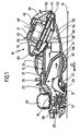
- a generally occupied by the reference numeral 10 self-propelled floor cleaning device is shown with a formed as a plastic injection molded chassis 12, on which two drive wheels 13, 14 are rotatably mounted, each by means of an electric drive motor 15 and 16 are driven in rotation.
- a lid can be placed, which forms a dust cover and to achieve better clarity in the FIGS. 1 and 2 not shown.
- the chassis 12 forms a substantially parallel to a bottom surface to be cleaned 19 aligned support plate 21 to which in the direction of travel 22 of the floor cleaning device 10 via a step 23 a also parallel to Floor surface 19 aligned support plate 24 and an aligned in the direction of the bottom surface 19 end wall 25 connect.
- a bottom plate 26 releasably connected, at whose front in the direction of travel 22 end support 27 support rollers 29 are freely rotatably mounted.
- the bottom plate 26 carries in its front region a Kehrschwelle 31 which dips into a bottom plate 26 by cross-suction opening 33 into which a substantially horizontally oriented suction channel 35 opens between the support plate 21, the step 23 and the support plate 24 on the one hand and the Bottom plate 26 on the other hand runs.
- a dirt filter 37 is held within the suction channel 35 obliquely to the longitudinal direction.
- the chassis 12 carries a suction turbine 40 with a turbine housing upper part 41 and a turbine housing lower part 42, which receive between them a turbine wheel 44 and an electric turbine drive 46.
- the turbine drive 46 is designed as an external rotor motor and comprises a rotatably held on the turbine housing top 46 stator 48 and a rotatably held on the stator 48 rotor 49 in the form of a stator 48 cross-hood 50, at the stator 48 facing the inside permanent magnets 51 are fixed and at the the turbine housing upper part 41 facing away from the bottom wall, the turbine wheel 44 is rotatably held.
- the turbine wheel 44 is drivable by means of the turbine drive 46 for a rotational movement about a turbine axis 54.
- the turbine axis 54 is aligned obliquely to the vertical and thus also obliquely to the longitudinal extent of the suction channel 35.
- the turbine wheel 44 is associated with an air inlet opening 56 of the suction turbine 40.
- the air inlet opening 56 is formed by an integrally connected to the turbine housing lower part 42 intake manifold 58, which establishes a flow connection between the suction passage 35 and the interior of the suction turbine 40th
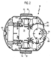
- the turbine wheel 44 is circumferentially surrounded by an outlet channel 60 which is configured spirally and continuously expanded in the flow direction and opens into an air outlet opening 62, wherein the air outlet opening 62 adjacent mouth region 64 of the outlet channel 60 is also aligned obliquely to the vertical.
- a suction flow symbolized by the arrows 66 can be generated within the suction channel 35, with the aid of which dirt can be transferred from the floor surface 19 to be cleaned into the suction channel 35 via the suction opening 33.
- the upstream of the dirt filter 37 arranged region of the suction channel 35 in this case forms a dirt receptacle 67th
- a brush roller 68 is rotatably supported on the chassis 12 in the region of the suction opening 33 with a rotational axis oriented transversely to the direction of travel 22 and parallel to the bottom surface 19.
- the drive of the brush roller 68 by means of a on the support plate 24 positioned electric brush drive 69 which is coupled via a known per se and therefore not shown in the drawing drive belt to the brush roller 68.
Landscapes
- Engineering & Computer Science (AREA)
- Mechanical Engineering (AREA)
- Nozzles For Electric Vacuum Cleaners (AREA)
- Electric Suction Cleaners (AREA)
Description
- Die Erfindung betrifft ein Bodenreinigungsgerät mit den Merkmalen des Oberbegriffes von Patentanspruch 1.
- Aus der internationalen Offenlegungsschrift
WO 99/28800 - Aus der europäischen Offenlegungsschrift
EP 0 635 236 A1 ist ein Bodenreinigungsgerät mit den Merkmalen des Oberbegriffes von Patentanspruch 1 bekannt. Dieses Bodenreinigungsgerät umfaßt einen Handstaubsauger, bei dem die Saugturbine mit schräg zur Vertikalen ausgerichteter Turbinenachse an den Saugkanal angesetzt ist. Der Handstaubsauger ist auf einer fahrbaren Plattform gehalten. - Aufgabe der vorliegenden Erfindung ist es, ein Bodenreinigungsgerät der eingangs genannten Art mit möglichst geringer Bauhöhe auszugestalten, wobei im Bereich der Saugöffnung eine möglichst starke Saugströmung erzielbar sein soll und das Bodenreinigungsgerät dennoch eine geringe Geräuschentwicklung aufweisen soll.
- Diese Aufgabe wird bei einem Bodenreinigungsgerät der gattungsgemäßen Art erfindungsgemäß dadurch gelöst, daß die Saugturbine als Axial-Radiallüfter ausgebildet ist und daß die Saugturbine einen in mindestens eine Luftauslaßöffnung einmündenden Auslaßkanal umfaßt, der das Turbinenrad in Umfangsrichtung umgibt und dessen Mündungsbereich in einem Winkel von etwa 60° bis ungefähr 80° zur Vertikalen ausgerichtet ist, wobei der Auslaßkanal spiralförmig ausgebildet ist und sich in Strömungsrichtung kontinuierlich erweitert.
- Die Ausrichtung der Saugturbine dergestalt, daß die Turbinenachse zur Vertikalen geneigt ist, ermöglicht es, die Bauhöhe des Bodenreinigungsgerätes auch bei Einsatz eines verhältnismäßig großen Turbinenrades gering zu halten. Außerdem hat eine derartige Anordnung den Vorteil, daß die von der Saugturbine hervorgerufene Saugströmung nur verhältnismäßig geringe Verluste durch im Verbindungsbereich zwischen Saugkanal und Saugturbine erfolgende Richtungsänderungen erleidet. Dies hat zur Folge, daß im Bereich der Saugöffnung eine verhältnismäßig starke Saugströmung erzeugt werden kann.
- Erfindungsgemäß ist die Saugturbine als Axial-Radiallüfter ausgebildet, mit dessen Hilfe die Arbeitsluft bezogen auf die Turbinenachse in axialer Richtung ansaugbar und in radialer Richtung abgebbar ist. Der Einsatz eines Axial-Radiallüfters ermöglicht den Aufbau einer hohen Druckdifferenz, so daß eine besonders starke Saugströmung erzielbar ist.
- Das erfindungsgemäße Bodenreinigungsgerät zeichnet sich durch eine verhältnismäßig geringe Bauhöhe aus. Dies ermöglicht es, mittels des Bodenreinigungsgerätes auch Bereiche der zu reinigenden Bodenfläche unterhalb von Heizkörpern, Möbelstücken und dergleichen zu erreichen. Die von der Saugturbine angesaugte Arbeitsluft wird nach Durchströmen des Schmutzaufnahmebehälters und der Saugturbine wieder an die Umgebung abgegeben. Um zu vermeiden, daß die abgegebene Arbeitsluft Schmutz aufwirbelt, der sich beispielsweise auf Heizkörpern niedergeschlagen hat, umfaßt die Saugturbine einen in mindestens eine Luftauslaßöffnung einmündenden Auslaßkanal, dessen Mündungsbereich schräg zur Vertikalen, nämlich in einem Winkel von etwa 60° bis ungefähr 80° zur Vertikalen ausgerichtet ist. Die Abluft kann mittels des schräg zur Vertikalen ausgerichteten Mündungsbereiches mit entsprechend schräg ausgerichteter Abluftströmung abgegeben werden, so daß die Gefahr vermindert wird, daß von der Abluftströmung Schmutz erfaßt wird, der sich beispielsweise auf Heizkörpern niedergeschlagen hat, wenn das Bodenreinigungsgerät unter den Heizkörpern positioniert wird.
- Eine geringe Geräuschentwicklung wird erfindungsgemäß dadurch erzielt, daß der Auslaßkanal spiralförmig ausgebildet ist und sich in Strömungsrichtung kontinuierlich erweitert. Bei einer derartigen Ausgestaltung kann sich die Abluft kontinuierlich ausdehnen, so daß eine schlagartige Luftausdehnung mit einer entsprechenden Geräuschentwicklung vermieden wird.
- Um die Geräuschentwicklung des Bodenreinigungsgerätes besonders gering zu halten, ist erfindungsgemäß vorgesehen, dass der Auslaßkanal das Turbinenrad in Umfangsrichtung umgibt. Dies ermöglicht es, trotz möglichst kompakt bauendem Bodenreinigungsgerät einen verhältnismäßig langen Auslaßkanal zu verwenden, wodurch die Geräuschentwicklung der Saugturbine reduziert werden kann. Der Einsatz eines langen Auslaßkanals hat außerdem eine Erhöhung der Druckdifferenz zwischen Einlaß und Auslaß der Saugturbine zur Folge, wodurch der Wirkungsgrad der Saugturbine verbessert wird.
- Das erfindungsgemäße Bodenreinigungsgerät zeichnet sich somit durch eine kompakte Ausgestaltung und eine besonders effektive Betriebsweise aus.
- Von Vorteil ist es, wenn die Turbinenachse in einem Winkel von ca. 15° bis etwa 75° zur Vertikalen ausgerichtet ist. Hierbei hat sich insbesondere ein Winkel von ca. 20° bis etwa 40° als besonders günstig erwiesen, um einerseits auftretende Strömungsverluste im Übergangsbereich zwischen dem horizontal ausgerichteten Saugkanal und der Saugturbine gering zu halten und andererseits unter Beachtung einer möglichst geringen Bauhöhe den Einsatz eines möglichst großen Turbinenrades zu ermöglichen.
- Zur Erzielung einer besonders effektiven Reinigungswirkung ist es von Vorteil, wenn das Bodenreinigungsgerät eine im Bereich der Saugöffnung angeordnete, rotierend antreibbare Bürstenwalze aufweist. Mittels der Bürstenwalze kann die zu reinigende Bodenfläche nicht nur abgesaugt, sondern zusätzlich gebürstet werden.
- Bei einer besonders bevorzugten Ausgestaltung des erfindungsgemäßen Bodenreinigungsgerätes ist vorgesehen, daß die Saugturbine einen elektrischen Außenläufermotor umfaßt mit einem an einem Tragelement gehaltenen Stator und einem um die Turbineachse drehbaren Rotor, an dem das Turbinenrad drehfest gehalten ist. Der Einsatz des Außenläufermotors ermöglicht es, den Motor auf der dem Saugkanal abgewandten Seite des Turbinenrades zu positionieren, ohne daß dies eine erhebliche Vergrößerung der Bauhöhe des Bodenreinigungsgerätes zur Folge hätte. Dies wiederum hat den Vorteil, daß der Saugkanal keine wesentlichen Querschnittsverengungen aufweist und sich somit durch einen möglichst geringen Strömungswiderstand auszeichnet.
- Das Bodenreinigungsgerät ist vorzugsweise selbstfahrend ausgestaltet. Es kann hierzu ein Fahrwerk aufweisen, an dem zwei elektromotorisch angetriebene Antriebsräder gelagert sind.
- Die nachfolgende Beschreibung einer bevorzugten Ausführungsform der Erfindung dient im Zusammenhang mit der Zeichnung der näheren Erläuterung. Es zeigen:
- Figur 1:
- eine schematische Schnittansicht eines Bodenreinigungsgerätes und
- Figur 2:
- eine Draufsicht auf das Bodenreinigungsgerät.
- In der Zeichnung ist ein insgesamt mit dem Bezugszeichen 10 belegtes selbstfahrendes Bodenreinigungsgerät dargestellt mit einem als Kunststoff-Spritzgußteil ausgebildeten Fahrwerk 12, an dem zwei Antriebsräder 13, 14 drehbar gelagert sind, die jeweils mittels eines elektrischen Antriebsmotors 15 bzw. 16 drehend antreibbar sind.
- Auf das Fahrwerk 12 kann ein Deckel aufgesetzt werden, der einen Staubschutz ausbildet und zur Erzielung einer besseren Übersichtlichkeit in den
Figuren 1 und2 nicht dargestellt ist. - Zwischen den beiden Antriebsrädern 13, 14 bildet das Fahrwerk 12 eine im wesentlichen parallel zu einer zu reinigenden Bodenfläche 19 ausgerichtete Tragplatte 21, an die sich in Fahrtrichtung 22 des Bodenreinigungsgerätes 10 über eine Stufe 23 eine ebenfalls parallel zur Bodenfläche 19 ausgerichtete Stützplatte 24 sowie eine in Richtung auf die Bodenfläche 19 ausgerichtete Stirnwand 25 anschließen.
- Im Abstand zur Tragplatte 21 ist am Fahrwerk 12 mittels an sich bekannter und deshalb in der Zeichnung nicht dargestellter Rastelemente eine Bodenplatte 26 lösbar verbindbar gehalten, an deren in Fahrtrichtung 22 vorderem Endbereich 27 Stützrollen 29 frei drehbar gelagert sind.
- Die Bodenplatte 26 trägt in ihrem vorderen Bereich eine Kehrschwelle 31, die in eine die Bodenplatte 26 durchgreifende Saugöffnung 33 eintaucht, in die ein im wesentlichen horizontal ausgerichteter Saugkanal 35 einmündet, der zwischen der Tragplatte 21, der Stufe 23 und der Stützplatte 24 einerseits und der Bodenplatte 26 andererseits verläuft. Innerhalb des Saugkanales 35 ist schräg zu dessen Längsrichtung ausgerichtet ein Schmutzfilter 37 gehalten.
- An seinem rückwärtigen Endbereich trägt das Fahrwerk 12 einen Saugturbine 40 mit einem Turbinengehäuseoberteil 41 und einem Turbinengehäuseunterteil 42, die zwischen sich ein Turbinenrad 44 sowie einen elektrischen Turbinenantrieb 46 aufnehmen.
- Der Turbinenantrieb 46 ist als Außenläufermotor ausgestaltet und umfaßt einen drehfest am Turbinengehäuseoberteil 46 gehaltenen Stator 48 sowie einen drehbar am Stator 48 gehaltenen Rotor 49 in Form einer den Stator 48 übergreifenden Haube 50, an deren dem Stator 48 zugewandter Innenseite Permanentmagnete 51 fixiert sind und an deren dem Turbinengehäuseoberteil 41 abgewandter Bodenwand das Turbinenrad 44 drehfest gehalten ist.
- Das Turbinenrad 44 ist mittels des Turbinenantriebes 46 zu einer Drehbewegung um eine Turbinenachse 54 antreibbar. Die Turbinenachse 54 ist schräg zur Vertikalen und somit auch schräg zur Längserstreckung des Saugkanales 35 ausgerichtet. Dem Turbinenrad 44 ist eine Lufteintrittsöffnung 56 der Saugturbine 40 zugeordnet. Die Lufteintrittsöffnung 56 wird von einem einstückig mit dem Turbinengehäuseunterteil 42 verbundenen Ansaugstutzen 58 ausgebildet, der eine Strömungsverbindung herstellt zwischen dem Saugkanal 35 und dem Inneren der Saugturbine 40.
- Wie insbesondere aus
Figur 2 deutlich wird, ist das Turbinenrad 44 in Umfangsrichtung von einem Auslaßkanal 60 umgeben, der spiralförmig ausgestaltet ist und sich in Strömungsrichtung kontinuierlich erweitert und in eine Luftaustrittsöffnung 62 einmündet, wobei der der Luftaustrittsöffnung 62 benachbarte Mündungsbereich 64 des Auslaßkanales 60 ebenfalls schräg zur Vertikalen ausgerichtet ist. - Mittels der Saugturbine 40 kann innerhalb des Saugkanales 35 eine durch die Pfeile 66 symbolisierte Saugströmung erzeugt werden, mit deren Hilfe von der zu reinigenden Bodenfläche 19 Schmutz über die Saugöffnung 33 in den Saugkanal 35 überführt werden kann. Der stromaufwärts des Schmutzfilters 37 angeordnete Bereich des Saugkanales 35 bildet hierbei einen Schmutzaufnahmebehälter 67.
- Um die Schmutzaufnahme zu verstärken, ist im Bereich der Saugöffnung 33 eine Bürstenwalze 68 mit quer zur Fahrtrichtung 22 und parallel zur Bodenfläche 19 ausgerichteter Drehachse drehbar am Fahrwerk 12 gehalten. Der Antrieb der Bürstenwalze 68 erfolgt mittels eines auf der Stützplatte 24 positionierten elektrischen Bürstenantriebes 69, der über einen an sich bekannten und deshalb in der Zeichnung nicht dargestellten Antriebsriemen mit der Bürstenwalze 68 gekoppelt ist.
- Da die Saugströmung 66 im Bereich des Saugkanales 35 sowie des schräg zur Vertikalen ausgerichteten Ansaugstutzens 58 nur geringe Strömungsverluste erleidet, kann im Bereich der Saugöffnung 33 eine starke Saugströmung erzielt werden, die in Kombination mit der Bürstenwalze 68 eine wirksame Bodenreinigung bewirkt. Durch die Saugströmung wird der von der Bürstenwalze 68 aufgewirbelte Schmutz erfaßt und in den Schmutzaufnahmebehälter 67 überführt. Die Ausrichtung der Saugturbine 40 mit schräg zur Vertikalen verlaufender Turbinenachse 54 ermöglicht hierbei den Einsatz eines verhältnismäßig großen Turbinenrades 44, wobei jedoch die Bauhöhe des Bodenreinigungsgerätes 10 gering gehalten werden kann.
Claims (5)
- Bodenreinigungsgerät umfassend eine Saugturbine (40) mit einem um eine Turbinenachse (54) drehend antreibbaren Turbinenrad (44), sowie einen im wesentlichen horizontal ausgerichteten Saugkanal (35), über den die Saugturbine (40) mit einer der zu reinigenden Bodenfläche (19) zugewandten Saugöffnung (33) in Strömungsverbindung steht, wobei der Saugkanal (35) einen Schmutzaufnahmebehälter (67) ausbildet und ein Schmutzfilter (37) aufnimmt und wobei die Saugturbine (40) mit schräg zur Vertikalen ausgerichteter Turbinenachse (54) an den Saugkanal (35) angesetzt ist, dadurch gekennzeichnet, daß die Saugturbine als Axial-Radiallüfter (40) ausgebildet ist, und daß die Saugturbine (40) einen in mindestens eine Luftauslaßöffnung (62) einmündenden Auslaßkanal (60) umfaßt, der das Turbinenrad (44) in Umfangsrichtung umgibt und dessen Mündungsbereich (64) in einem Winkel von etwa 60° bis ungefähr 80° zur Vertikalen ausgerichtet ist, wobei der Auslaßkanal (60) spiralförmig ausgebildet ist und sich in Strömungsrichtung kontinuierlich erweitert.
- Bodenreinigungsgerät nach Anspruch 1, dadurch gekennzeichnet, daß die Turbinenachse (54) in einem Winkel von ca. 15° bis etwa 75° zur Vertikalen ausgerichtet ist.
- Bodenreinigungsgerät nach Anspruch 1 oder 2, dadurch gekennzeichnet, daß das Bodenreinigungsgerät (10) eine im Bereich der Saugöffnung (33) angeordnete, rotierend antreibbare Bürstenwalze (68) aufweist.
- Bodenreinigungsgerät nach einem der voranstehenden Ansprüche, dadurch gekennzeichnet, daß die Saugturbine (40) einen elektrischen Außenläufermotor (46) umfaßt mit einem an einem Tragelement (41) gehaltenen Stator (48) und einem um die Turbinenachse (54) drehbaren Rotor (49), an dem das Turbinenrad (44) drehfest gehalten ist.
- Bodenreinigungsgerät nach einem der voranstehenden Ansprüche, dadurch gekennzeichnet, daß das Bodenreinigungsgerät (10) selbstfahrend ausgestaltet ist.
Applications Claiming Priority (3)
| Application Number | Priority Date | Filing Date | Title |
|---|---|---|---|
| DE10110907A DE10110907A1 (de) | 2001-03-07 | 2001-03-07 | Bodenreinigungsgerät |
| DE10110907 | 2001-03-07 | ||
| PCT/EP2002/002127 WO2002069774A1 (de) | 2001-03-07 | 2002-02-28 | Bobenreinigungsgerät |
Publications (2)
| Publication Number | Publication Date |
|---|---|
| EP1365674A1 EP1365674A1 (de) | 2003-12-03 |
| EP1365674B1 true EP1365674B1 (de) | 2008-12-31 |
Family
ID=7676577
Family Applications (1)
| Application Number | Title | Priority Date | Filing Date |
|---|---|---|---|
| EP02703606A Expired - Lifetime EP1365674B1 (de) | 2001-03-07 | 2002-02-28 | Bodenreinigungsgerät mit geringer bauhöhe |
Country Status (6)
| Country | Link |
|---|---|
| US (1) | US20040074044A1 (de) |
| EP (1) | EP1365674B1 (de) |
| CN (1) | CN1239119C (de) |
| AT (1) | ATE418902T1 (de) |
| DE (2) | DE10110907A1 (de) |
| WO (1) | WO2002069774A1 (de) |
Cited By (1)
| Publication number | Priority date | Publication date | Assignee | Title |
|---|---|---|---|---|
| WO2014094834A1 (de) | 2012-12-18 | 2014-06-26 | Alfred Kärcher Gmbh & Co. Kg | Selbstfahrendes und selbstlenkendes bodenreinigungsgerät |
Families Citing this family (38)
| Publication number | Priority date | Publication date | Assignee | Title |
|---|---|---|---|---|
| US8412377B2 (en) | 2000-01-24 | 2013-04-02 | Irobot Corporation | Obstacle following sensor scheme for a mobile robot |
| US8788092B2 (en) | 2000-01-24 | 2014-07-22 | Irobot Corporation | Obstacle following sensor scheme for a mobile robot |
| US6956348B2 (en) | 2004-01-28 | 2005-10-18 | Irobot Corporation | Debris sensor for cleaning apparatus |
| US6690134B1 (en) | 2001-01-24 | 2004-02-10 | Irobot Corporation | Method and system for robot localization and confinement |
| US7571511B2 (en) | 2002-01-03 | 2009-08-11 | Irobot Corporation | Autonomous floor-cleaning robot |
| US8396592B2 (en) | 2001-06-12 | 2013-03-12 | Irobot Corporation | Method and system for multi-mode coverage for an autonomous robot |
| US7429843B2 (en) | 2001-06-12 | 2008-09-30 | Irobot Corporation | Method and system for multi-mode coverage for an autonomous robot |
| US9128486B2 (en) | 2002-01-24 | 2015-09-08 | Irobot Corporation | Navigational control system for a robotic device |
| AU2003248102A1 (en) * | 2002-07-25 | 2004-02-16 | Toshiba Tec Kabushiki Kaisha | Vacuum cleaner |
| US8428778B2 (en) | 2002-09-13 | 2013-04-23 | Irobot Corporation | Navigational control system for a robotic device |
| US8386081B2 (en) | 2002-09-13 | 2013-02-26 | Irobot Corporation | Navigational control system for a robotic device |
| US7332890B2 (en) | 2004-01-21 | 2008-02-19 | Irobot Corporation | Autonomous robot auto-docking and energy management systems and methods |
| DE112005000738T5 (de) | 2004-03-29 | 2007-04-26 | Evolution Robotics, Inc., Pasadena | Verfahren und Vorrichtung zur Positionsbestimmung unter Verwendung von reflektierten Lichtquellen |
| KR101214723B1 (ko) | 2004-06-24 | 2012-12-24 | 아이로보트 코퍼레이션 | 자동 로봇 장치용의 원격 제어 스케줄러 및 방법 |
| US7706917B1 (en) | 2004-07-07 | 2010-04-27 | Irobot Corporation | Celestial navigation system for an autonomous robot |
| US8972052B2 (en) | 2004-07-07 | 2015-03-03 | Irobot Corporation | Celestial navigation system for an autonomous vehicle |
| US8392021B2 (en) | 2005-02-18 | 2013-03-05 | Irobot Corporation | Autonomous surface cleaning robot for wet cleaning |
| US7620476B2 (en) | 2005-02-18 | 2009-11-17 | Irobot Corporation | Autonomous surface cleaning robot for dry cleaning |
| ES2346343T3 (es) | 2005-02-18 | 2010-10-14 | Irobot Corporation | Robot autonomo de limpieza de superficies para una limpieza en seco y en mojado. |
| US8930023B2 (en) | 2009-11-06 | 2015-01-06 | Irobot Corporation | Localization by learning of wave-signal distributions |
| KR101300492B1 (ko) | 2005-12-02 | 2013-09-02 | 아이로보트 코퍼레이션 | 커버리지 로봇 이동성 |
| US8584305B2 (en) | 2005-12-02 | 2013-11-19 | Irobot Corporation | Modular robot |
| EP2533120B1 (de) | 2005-12-02 | 2019-01-16 | iRobot Corporation | Robotersystem |
| EP2829939B1 (de) | 2005-12-02 | 2019-11-13 | iRobot Corporation | Roboternavigationssystem mit autonomer Abdeckung |
| EP2816434A3 (de) * | 2005-12-02 | 2015-01-28 | iRobot Corporation | Roboter mit autonomem Wirkungsbereich |
| US8528157B2 (en) | 2006-05-19 | 2013-09-10 | Irobot Corporation | Coverage robots and associated cleaning bins |
| US8417383B2 (en) | 2006-05-31 | 2013-04-09 | Irobot Corporation | Detecting robot stasis |
| US20080276413A1 (en) | 2007-03-06 | 2008-11-13 | Kurt Clarence Adelman | Integral Vacuum Fan Housing |
| ES2559128T3 (es) | 2007-05-09 | 2016-02-10 | Irobot Corporation | Robot autónomo de cubrimiento compacto |
| DE102008008069A1 (de) * | 2008-02-01 | 2009-08-06 | Alfred Kärcher Gmbh & Co. Kg | Bodenreinigungsgerät |
| JP5073609B2 (ja) * | 2008-08-11 | 2012-11-14 | 日東電工株式会社 | 光導波路の製造方法 |
| KR101497197B1 (ko) | 2010-02-16 | 2015-02-27 | 아이로보트 코퍼레이션 | 진공 브러쉬 |
| CN105848549B (zh) * | 2013-12-06 | 2018-03-06 | 阿尔弗雷德·凯驰两合公司 | 自行驶且自转向的地板清洁设备和清洁系统 |
| JP6391976B2 (ja) * | 2014-04-22 | 2018-09-19 | 東芝ライフスタイル株式会社 | 電気掃除機 |
| DE102015105587A1 (de) * | 2015-04-13 | 2016-10-13 | Alfred Kärcher Gmbh & Co. Kg | Bodenreinigungsmaschine |
| WO2017096716A1 (zh) * | 2015-12-10 | 2017-06-15 | 江苏美的清洁电器股份有限公司 | 立式吸尘器 |
| US10292554B2 (en) | 2016-10-28 | 2019-05-21 | Irobot Corporation | Mobile cleaning robot with a bin |
| CN107725480A (zh) * | 2017-04-10 | 2018-02-23 | 宁波华宝海之创机器人科技有限公司 | 一种具有吸附力强的扫地机的风扇机构 |
Family Cites Families (18)
| Publication number | Priority date | Publication date | Assignee | Title |
|---|---|---|---|---|
| US1485188A (en) * | 1919-11-06 | 1924-02-26 | Electric Vacuum Cleaner Co | Suction cleaner |
| US1556021A (en) * | 1922-01-30 | 1925-10-06 | William V Orr | Suction cleaner |
| US1965885A (en) * | 1930-04-17 | 1934-07-10 | Delco Remy Corp | Suction cleaner |
| US1880915A (en) * | 1930-04-17 | 1932-10-04 | Delco Remy Corp | Suction cleaner |
| US2058371A (en) * | 1931-12-21 | 1936-10-20 | Hugo Van Rosen | Cleaner |
| US2036056A (en) * | 1934-06-07 | 1936-03-31 | Electric Vacuum Cleaner Co | Vacuum cleaner |
| GB568958A (en) * | 1943-09-22 | 1945-04-27 | Gen Electric Co Ltd | Improvements in vacuum cleaners |
| US2388280A (en) * | 1943-09-27 | 1945-11-06 | Air Way Electric Appl Corp | Suction cleaner |
| US2499330A (en) * | 1944-08-12 | 1950-02-28 | Gen Motors Corp | Vacuum cleaner |
| US2730750A (en) * | 1951-05-05 | 1956-01-17 | Hoover Co | Low height suction cleaner arrangement |
| NL6710948A (de) * | 1966-08-10 | 1968-02-12 | Eck Bruno Dr Ing | |
| US4120616A (en) * | 1975-10-06 | 1978-10-17 | Breuer Electric Manufacturing Company | Vacuum cleaner-blower assembly with sound absorbing arrangement |
| GB2146518B (en) * | 1983-09-14 | 1986-10-29 | John Mfg Ltd | Rechargeable battery vacuum cleaner |
| JP3047984B2 (ja) * | 1990-04-18 | 2000-06-05 | 株式会社日立製作所 | 電気掃除機 |
| IT1264951B1 (it) * | 1993-07-20 | 1996-10-17 | Anna Maria Boesi | Apparecchiatura aspirante per la pulizia di superfici |
| DE59701239D1 (de) * | 1996-01-11 | 2000-04-20 | Patent Ag Chur Sa | Elektromotorisch angetriebenes Bypass-Gebläse |
| WO1999028800A1 (fr) * | 1997-11-27 | 1999-06-10 | Solar & Robotics | Ameliorations a des robots mobiles et a leur systeme de commande |
| DE19919844A1 (de) * | 1999-04-30 | 2000-11-02 | Kaercher Gmbh & Co Alfred | Bodenreinigungsgerät |
-
2001
- 2001-03-07 DE DE10110907A patent/DE10110907A1/de not_active Ceased
-
2002
- 2002-02-28 CN CN02805969.7A patent/CN1239119C/zh not_active Expired - Lifetime
- 2002-02-28 EP EP02703606A patent/EP1365674B1/de not_active Expired - Lifetime
- 2002-02-28 WO PCT/EP2002/002127 patent/WO2002069774A1/de not_active Ceased
- 2002-02-28 AT AT02703606T patent/ATE418902T1/de not_active IP Right Cessation
- 2002-02-28 DE DE50213166T patent/DE50213166D1/de not_active Expired - Lifetime
-
2003
- 2003-08-15 US US10/641,734 patent/US20040074044A1/en not_active Abandoned
Cited By (1)
| Publication number | Priority date | Publication date | Assignee | Title |
|---|---|---|---|---|
| WO2014094834A1 (de) | 2012-12-18 | 2014-06-26 | Alfred Kärcher Gmbh & Co. Kg | Selbstfahrendes und selbstlenkendes bodenreinigungsgerät |
Also Published As
| Publication number | Publication date |
|---|---|
| CN1239119C (zh) | 2006-02-01 |
| DE50213166D1 (de) | 2009-02-12 |
| DE10110907A1 (de) | 2002-09-19 |
| ATE418902T1 (de) | 2009-01-15 |
| WO2002069774A1 (de) | 2002-09-12 |
| CN1494392A (zh) | 2004-05-05 |
| EP1365674A1 (de) | 2003-12-03 |
| US20040074044A1 (en) | 2004-04-22 |
Similar Documents
| Publication | Publication Date | Title |
|---|---|---|
| EP1365674A1 (de) | Bodenreinigungsgerät | |
| DE10035253B4 (de) | Staubsauger | |
| EP2408972B1 (de) | Selbstfahrende kehrmaschine | |
| DE10231390A1 (de) | Sauggerät für Reinigungszwecke | |
| EP2316322A2 (de) | Reinigungsroboter | |
| CH640126A5 (de) | Nassreinigungs-sauggeblaesevorrichtung. | |
| EP3021723B1 (de) | Tragbares hartflächenreinigungsgerät | |
| WO2011154092A1 (de) | Vorrichtung zum absaugen oder verdichten eines arbeitsfluids | |
| WO2009144257A2 (de) | Laubsauger | |
| EP2320780A1 (de) | Staubsauger | |
| EP2640250B1 (de) | Fahrbares bodenreinigungsgerät mit geräuschdämmung | |
| EP2808553B1 (de) | Elektromotor mit Gebläserad | |
| EP3739126A1 (de) | Selbstfahrende kehrmaschine | |
| EP2320783B1 (de) | Staubsauger | |
| EP2330958B1 (de) | Staubsauger | |
| EP3047770B1 (de) | Bodenstaubsauger | |
| EP0933056A2 (de) | Schmutzsauger | |
| DE20317886U1 (de) | Fahrbares Bodenreinigungsgerät | |
| KR200232588Y1 (ko) | 내연기관을 이용한 진공청소장비 | |
| EP4111923A1 (de) | Bodenreinigungsmaschine | |
| EP4649870A1 (de) | Saugreinigungsgerät | |
| EP2428149B1 (de) | Saugreinigungsvorrichtung | |
| DE102011113687A1 (de) | Saugeinrichtung für den dentalmedizinischen Bereich | |
| EP1903924A1 (de) | Staubsauger | |
| DE102005047073A1 (de) | Staubsauger mit Fliehkraftabscheider |
Legal Events
| Date | Code | Title | Description |
|---|---|---|---|
| PUAI | Public reference made under article 153(3) epc to a published international application that has entered the european phase |
Free format text: ORIGINAL CODE: 0009012 |
|
| 17P | Request for examination filed |
Effective date: 20030717 |
|
| AK | Designated contracting states |
Kind code of ref document: A1 Designated state(s): AT BE CH CY DE DK ES FI FR GB GR IE IT LI LU MC NL PT SE TR |
|
| AX | Request for extension of the european patent |
Extension state: AL LT LV MK RO SI |
|
| 17Q | First examination report despatched |
Effective date: 20051114 |
|
| GRAP | Despatch of communication of intention to grant a patent |
Free format text: ORIGINAL CODE: EPIDOSNIGR1 |
|
| RTI1 | Title (correction) |
Free format text: FLOOR CLEANING DEVICE OF SMALL HEIGHT |
|
| GRAS | Grant fee paid |
Free format text: ORIGINAL CODE: EPIDOSNIGR3 |
|
| GRAA | (expected) grant |
Free format text: ORIGINAL CODE: 0009210 |
|
| AK | Designated contracting states |
Kind code of ref document: B1 Designated state(s): AT BE CH CY DE DK ES FI FR GB GR IE IT LI LU MC NL PT SE TR |
|
| REG | Reference to a national code |
Ref country code: CH Ref legal event code: EP Ref country code: GB Ref legal event code: FG4D Free format text: NOT ENGLISH Ref country code: CH Ref legal event code: NV Representative=s name: ISLER & PEDRAZZINI AG |
|
| REF | Corresponds to: |
Ref document number: 50213166 Country of ref document: DE Date of ref document: 20090212 Kind code of ref document: P |
|
| REG | Reference to a national code |
Ref country code: IE Ref legal event code: FG4D Free format text: LANGUAGE OF EP DOCUMENT: GERMAN |
|
| PG25 | Lapsed in a contracting state [announced via postgrant information from national office to epo] |
Ref country code: FI Free format text: LAPSE BECAUSE OF FAILURE TO SUBMIT A TRANSLATION OF THE DESCRIPTION OR TO PAY THE FEE WITHIN THE PRESCRIBED TIME-LIMIT Effective date: 20081231 Ref country code: NL Free format text: LAPSE BECAUSE OF FAILURE TO SUBMIT A TRANSLATION OF THE DESCRIPTION OR TO PAY THE FEE WITHIN THE PRESCRIBED TIME-LIMIT Effective date: 20081231 |
|
| NLV1 | Nl: lapsed or annulled due to failure to fulfill the requirements of art. 29p and 29m of the patents act | ||
| PG25 | Lapsed in a contracting state [announced via postgrant information from national office to epo] |
Ref country code: ES Free format text: LAPSE BECAUSE OF FAILURE TO SUBMIT A TRANSLATION OF THE DESCRIPTION OR TO PAY THE FEE WITHIN THE PRESCRIBED TIME-LIMIT Effective date: 20090411 |
|
| REG | Reference to a national code |
Ref country code: IE Ref legal event code: FD4D |
|
| BERE | Be: lapsed |
Owner name: ALFRED KARCHER G.M.B.H. & CO. KG Effective date: 20090228 |
|
| PG25 | Lapsed in a contracting state [announced via postgrant information from national office to epo] |
Ref country code: SE Free format text: LAPSE BECAUSE OF FAILURE TO SUBMIT A TRANSLATION OF THE DESCRIPTION OR TO PAY THE FEE WITHIN THE PRESCRIBED TIME-LIMIT Effective date: 20090331 Ref country code: PT Free format text: LAPSE BECAUSE OF FAILURE TO SUBMIT A TRANSLATION OF THE DESCRIPTION OR TO PAY THE FEE WITHIN THE PRESCRIBED TIME-LIMIT Effective date: 20090601 |
|
| PG25 | Lapsed in a contracting state [announced via postgrant information from national office to epo] |
Ref country code: MC Free format text: LAPSE BECAUSE OF NON-PAYMENT OF DUE FEES Effective date: 20090228 |
|
| PG25 | Lapsed in a contracting state [announced via postgrant information from national office to epo] |
Ref country code: IE Free format text: LAPSE BECAUSE OF FAILURE TO SUBMIT A TRANSLATION OF THE DESCRIPTION OR TO PAY THE FEE WITHIN THE PRESCRIBED TIME-LIMIT Effective date: 20081231 Ref country code: DK Free format text: LAPSE BECAUSE OF FAILURE TO SUBMIT A TRANSLATION OF THE DESCRIPTION OR TO PAY THE FEE WITHIN THE PRESCRIBED TIME-LIMIT Effective date: 20081231 |
|
| PLBE | No opposition filed within time limit |
Free format text: ORIGINAL CODE: 0009261 |
|
| STAA | Information on the status of an ep patent application or granted ep patent |
Free format text: STATUS: NO OPPOSITION FILED WITHIN TIME LIMIT |
|
| GBPC | Gb: european patent ceased through non-payment of renewal fee |
Effective date: 20090331 |
|
| REG | Reference to a national code |
Ref country code: FR Ref legal event code: ST Effective date: 20091030 |
|
| 26N | No opposition filed |
Effective date: 20091001 |
|
| PG25 | Lapsed in a contracting state [announced via postgrant information from national office to epo] |
Ref country code: BE Free format text: LAPSE BECAUSE OF NON-PAYMENT OF DUE FEES Effective date: 20090228 |
|
| PG25 | Lapsed in a contracting state [announced via postgrant information from national office to epo] |
Ref country code: GB Free format text: LAPSE BECAUSE OF NON-PAYMENT OF DUE FEES Effective date: 20090331 Ref country code: FR Free format text: LAPSE BECAUSE OF NON-PAYMENT OF DUE FEES Effective date: 20090302 |
|
| PG25 | Lapsed in a contracting state [announced via postgrant information from national office to epo] |
Ref country code: AT Free format text: LAPSE BECAUSE OF NON-PAYMENT OF DUE FEES Effective date: 20090228 |
|
| PG25 | Lapsed in a contracting state [announced via postgrant information from national office to epo] |
Ref country code: GR Free format text: LAPSE BECAUSE OF FAILURE TO SUBMIT A TRANSLATION OF THE DESCRIPTION OR TO PAY THE FEE WITHIN THE PRESCRIBED TIME-LIMIT Effective date: 20090401 |
|
| PG25 | Lapsed in a contracting state [announced via postgrant information from national office to epo] |
Ref country code: LU Free format text: LAPSE BECAUSE OF NON-PAYMENT OF DUE FEES Effective date: 20090228 |
|
| PG25 | Lapsed in a contracting state [announced via postgrant information from national office to epo] |
Ref country code: TR Free format text: LAPSE BECAUSE OF FAILURE TO SUBMIT A TRANSLATION OF THE DESCRIPTION OR TO PAY THE FEE WITHIN THE PRESCRIBED TIME-LIMIT Effective date: 20081231 |
|
| PG25 | Lapsed in a contracting state [announced via postgrant information from national office to epo] |
Ref country code: CY Free format text: LAPSE BECAUSE OF FAILURE TO SUBMIT A TRANSLATION OF THE DESCRIPTION OR TO PAY THE FEE WITHIN THE PRESCRIBED TIME-LIMIT Effective date: 20081231 |
|
| REG | Reference to a national code |
Ref country code: DE Ref legal event code: R082 Ref document number: 50213166 Country of ref document: DE Representative=s name: HOEGER, STELLRECHT & PARTNER PATENTANWAELTE MB, DE |
|
| PGFP | Annual fee paid to national office [announced via postgrant information from national office to epo] |
Ref country code: CH Payment date: 20160211 Year of fee payment: 15 Ref country code: DE Payment date: 20160323 Year of fee payment: 15 Ref country code: IT Payment date: 20160222 Year of fee payment: 15 |
|
| REG | Reference to a national code |
Ref country code: DE Ref legal event code: R119 Ref document number: 50213166 Country of ref document: DE |
|
| REG | Reference to a national code |
Ref country code: CH Ref legal event code: PL |
|
| PG25 | Lapsed in a contracting state [announced via postgrant information from national office to epo] |
Ref country code: CH Free format text: LAPSE BECAUSE OF NON-PAYMENT OF DUE FEES Effective date: 20170228 Ref country code: LI Free format text: LAPSE BECAUSE OF NON-PAYMENT OF DUE FEES Effective date: 20170228 |
|
| PG25 | Lapsed in a contracting state [announced via postgrant information from national office to epo] |
Ref country code: DE Free format text: LAPSE BECAUSE OF NON-PAYMENT OF DUE FEES Effective date: 20170901 |
|
| PG25 | Lapsed in a contracting state [announced via postgrant information from national office to epo] |
Ref country code: IT Free format text: LAPSE BECAUSE OF NON-PAYMENT OF DUE FEES Effective date: 20170228 |