EP1365352B1 - Bilderzeugungsgerät - Google Patents
Bilderzeugungsgerät Download PDFInfo
- Publication number
- EP1365352B1 EP1365352B1 EP03252939A EP03252939A EP1365352B1 EP 1365352 B1 EP1365352 B1 EP 1365352B1 EP 03252939 A EP03252939 A EP 03252939A EP 03252939 A EP03252939 A EP 03252939A EP 1365352 B1 EP1365352 B1 EP 1365352B1
- Authority
- EP
- European Patent Office
- Prior art keywords
- laser beam
- photoconductor
- unit
- color
- image
- Prior art date
- Legal status (The legal status is an assumption and is not a legal conclusion. Google has not performed a legal analysis and makes no representation as to the accuracy of the status listed.)
- Expired - Lifetime
Links
Images


Classifications
-
- G—PHYSICS
- G06—COMPUTING OR CALCULATING; COUNTING
- G06K—GRAPHICAL DATA READING; PRESENTATION OF DATA; RECORD CARRIERS; HANDLING RECORD CARRIERS
- G06K15/00—Arrangements for producing a permanent visual presentation of the output data, e.g. computer output printers
- G06K15/02—Arrangements for producing a permanent visual presentation of the output data, e.g. computer output printers using printers
- G06K15/12—Arrangements for producing a permanent visual presentation of the output data, e.g. computer output printers using printers by photographic printing, e.g. by laser printers
- G06K15/1204—Arrangements for producing a permanent visual presentation of the output data, e.g. computer output printers using printers by photographic printing, e.g. by laser printers involving the fast moving of an optical beam in the main scanning direction
- G06K15/1219—Detection, control or error compensation of scanning velocity or position, e.g. synchronisation
-
- G—PHYSICS
- G03—PHOTOGRAPHY; CINEMATOGRAPHY; ANALOGOUS TECHNIQUES USING WAVES OTHER THAN OPTICAL WAVES; ELECTROGRAPHY; HOLOGRAPHY
- G03G—ELECTROGRAPHY; ELECTROPHOTOGRAPHY; MAGNETOGRAPHY
- G03G15/00—Apparatus for electrographic processes using a charge pattern
- G03G15/01—Apparatus for electrographic processes using a charge pattern for producing multicoloured copies
Definitions
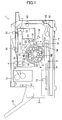
- the polygon mirror 32 has six mirror surfaces.
- the optical element unit 70 is installed movably. When a toner image is formed on the photoconductor belt 23, the optical element unit 70 is moved driven by the beam position control circuit 83 and the beam position adjustment motor 75, and thereby the beam spot on the photoconductor belt 23 is displaced in the sub scanning direction.
- the beam position control circuit 83 and the beam position adjustment motor 75 are controlled based on a count from the counter 82 representing the time difference between the ITT signal from the mark detection sensor 8 indicating one turning cycle of the intermediate transfer belt 51 and the main scanning synchronization signal output from the synchronization detection sensor 36 indicating writing timing of the laser beam 37 on the photo conduct belt 23.
- the rotational center axis OS of the optical element unit 70 is deviated from the optical axis of the laser beam 37 mainly in the main scanning direction.
Landscapes
- Physics & Mathematics (AREA)
- General Physics & Mathematics (AREA)
- Engineering & Computer Science (AREA)
- Optics & Photonics (AREA)
- General Engineering & Computer Science (AREA)
- Theoretical Computer Science (AREA)
- Color Electrophotography (AREA)
- Electrostatic Charge, Transfer And Separation In Electrography (AREA)
- Mechanical Optical Scanning Systems (AREA)
- Facsimile Heads (AREA)
- Exposure Or Original Feeding In Electrophotography (AREA)
- Electrophotography Configuration And Component (AREA)
- Control Or Security For Electrophotography (AREA)
- Facsimile Scanning Arrangements (AREA)
- Laser Beam Printer (AREA)
- Fax Reproducing Arrangements (AREA)
Claims (5)
- Bilderzeugungsvorrichtung, die umfasst:eine Einheit (70) mit optischem Element, die beweglich installiert ist und eine Laseremissionseinheit zum Emittieren eines Laserstrahlenbündels enthält, wobei die Laseremissionseinheit an der Einheit mit optischem Element einteilig befestigt ist;eine rotierende Ablenkeinrichtung (32), um das emittierte Laserstrahlenbündel abzusenken, während sie sich dreht;einen Photoleiter (23), derart, dass ein Bild einer Farbe auf dem Photoleiter erzeugt wird, wenn der Photoleiter mit dem abgelenkten Laserstrahlenbündel überstrichen wird, und durch einen Entwicklungsagenten bearbeitet wird, und der derart positioniert ist, dass sich ein Fleck des Laserstrahlenbündels auf dem Photoleiter in einer ersten Richtung bewegt, wenn das Laserstrahlenbündel durch die rotierende Ablenkeinrichtung abgelenkt wird;ein drehbares Übertragungselement (51), das mit dem Photoleiter in Kontakt ist, wobei mehrere der Bilder unterschiedlicher Farbe, die auf dem Photoleiter erzeugt werden, nacheinander jedes Mal, wenn sich das drehbare Übertragungselement um einen Zyklus dreht, an eine vorgegebene Position auf dem drehbaren Übertragurtgselement übertragen werden, wobei die übertragenen Bilder auf dem drehbaren Überfiragungselement ein Farbbild ergeben;eine erste Detektionseinheit (8), die in der Nähe des drehbaren Übertragungselements angeordnet ist, um jedes Mal, wenn sich das drehbare Übertragungselement um einen Zyklus dreht, ein erstes Signal auszugeben;eine zweite Detektionseinheit (36), die zwischen der rotierenden Ablenkeinrichtung und dem Photoleiter angeordnet ist, um das abgelenkte Laserstrahlenbündel zu detektieren und ein zweites Signal auszugeben, wenn das Laserstrahlenbündel beginnt, den Photoleiter in der ersten Richtung zu überstreichen; undeine Recheneinheit (1), die dafür ausgelegt ist, einen Zeitunterschied zwischen dem ersten Signal und dem zweiten Signal zu berechnen, gekennzeichnet durch:eine Verlagerungsantriebseinheit (75, 76), die mit der Einheit mit optischem Element verbunden ist, um die Einheit mit optischem Element um eine Drehachse zu drehen, wobei die Drehachse von einer optischen Achse des von der Laseremissionseinheit emittierten Laserstrahlenbündels abweicht, wobei der Fleck des Laserstrahlenbündels auf dem Photoleiter in einer zweiten Richtung verlagert wird, wenn die Einheit mit optischem Element durch die Verlagerungsantriebseinheit bewegt wird;wobei die Verlagerungsantriebseinheit dafür ausgelegt ist, die Einheit mit optischem Element zu bewegen, um den Fleck des Laserstrahlenbirindels um eine Strecke in der zweiten Richtung zu verlagern, um eine Startposition der Erzeugung jedes der mehreren Bilder unterschiedlicher Farbe auf dem Photoleiter zu verändern, wobei die Strecke durch den Zeitunterschied bestimmt ist.
- Bilderzeugungsvorrichtung nach Anspruch 1, wobei
mehrere Referenzmarkierungen (66A-F) auf dem drehbaren Übertragungselement in regelmäßigen Intervallen gebildet sind; und
die erste Detektionseinheit (8) dafür ausgelegt ist, das erste Signal jedes Mal auszugeben, wenn eine Bestimmte der Referenzmarkierungen detektiert wird. - Bilderzeugungsvorrichtung nach Anspruch 1 oder 2, wobei
das drehbare Übertragungselement (51) riemenartig oder trommelartig ist; und
das drehbare Übertragungselement dafür ausgelegt ist, ferner das darauf befindliche Farbbild auf ein Bildträgerelement zu übertragen. - Bilderzeugungsvorrichtung nach Anspruch 1, 2 oder 3, wobei die Drehachse von der optischen Achse des Laserstrahlenbündels in einer Ebene abweicht, die durch das durch die rotierende Ablenkeinrichtung abgelenkte Laserstrahlenbündel gebildet wird.
- Bilderzeugungsvorrichtung nach Anspruch 4, wobei sich die Drehachse der Einheit mit optischem Element und die optische Achse des Laserstrahlenbündels ungefähr an derselben Position auf der rotierenden Ablenkeinrichtung schneiden.
Applications Claiming Priority (2)
| Application Number | Priority Date | Filing Date | Title |
|---|---|---|---|
| JP2002138932A JP4139135B2 (ja) | 2002-05-14 | 2002-05-14 | 画像形成装置 |
| JP2002138932 | 2002-05-14 |
Publications (3)
| Publication Number | Publication Date |
|---|---|
| EP1365352A2 EP1365352A2 (de) | 2003-11-26 |
| EP1365352A3 EP1365352A3 (de) | 2010-06-23 |
| EP1365352B1 true EP1365352B1 (de) | 2012-12-12 |
Family
ID=29397586
Family Applications (1)
| Application Number | Title | Priority Date | Filing Date |
|---|---|---|---|
| EP03252939A Expired - Lifetime EP1365352B1 (de) | 2002-05-14 | 2003-05-12 | Bilderzeugungsgerät |
Country Status (4)
| Country | Link |
|---|---|
| US (1) | US6873346B2 (de) |
| EP (1) | EP1365352B1 (de) |
| JP (1) | JP4139135B2 (de) |
| KR (1) | KR100523345B1 (de) |
Families Citing this family (11)
| Publication number | Priority date | Publication date | Assignee | Title |
|---|---|---|---|---|
| JP2005148128A (ja) * | 2003-11-11 | 2005-06-09 | Ricoh Co Ltd | 光書込装置及び画像形成装置 |
| US7632620B2 (en) * | 2005-01-28 | 2009-12-15 | Xerox Corporation | Coated carrier |
| JP4694926B2 (ja) | 2005-09-16 | 2011-06-08 | 株式会社リコー | 光走査装置及び画像形成装置 |
| CN100578378C (zh) * | 2006-01-25 | 2010-01-06 | 株式会社理光 | 图像形成装置 |
| JP4927481B2 (ja) * | 2006-09-05 | 2012-05-09 | 株式会社リコー | 光走査装置及び画像形成装置 |
| US8044986B2 (en) * | 2007-03-12 | 2011-10-25 | Canon Kabushiki Kaisha | Image forming apparatus and method for controlling the same |
| JP4918439B2 (ja) * | 2007-09-04 | 2012-04-18 | 株式会社リコー | 光書込装置及び画像形成装置 |
| JP5033548B2 (ja) * | 2007-09-10 | 2012-09-26 | 株式会社リコー | 光書込装置及び画像形成装置 |
| JP5022945B2 (ja) | 2008-02-29 | 2012-09-12 | 株式会社リコー | 光書込装置及び画像形成装置 |
| JP2011133861A (ja) * | 2009-11-30 | 2011-07-07 | Canon Inc | 画像形成装置 |
| KR101250587B1 (ko) | 2010-04-20 | 2013-04-03 | 연세대학교 산학협력단 | 전이금속 산화물/탄소나노튜브 복합체 제조 방법 및 그 복합체 |
Family Cites Families (19)
| Publication number | Priority date | Publication date | Assignee | Title |
|---|---|---|---|---|
| JP2672313B2 (ja) * | 1988-01-18 | 1997-11-05 | キヤノン株式会社 | 画像形成装置 |
| US5315322A (en) | 1990-02-21 | 1994-05-24 | Ricoh Company, Ltd. | Image forming apparatus with anti-banding implementation |
| JP3159727B2 (ja) | 1990-10-11 | 2001-04-23 | 株式会社リコー | 給紙装置 |
| JP3310685B2 (ja) | 1991-03-20 | 2002-08-05 | 株式会社リコー | 画像形成装置 |
| US5297376A (en) | 1991-07-05 | 1994-03-29 | Ricoh Company, Ltd. | Finisher for an image forming apparatus |
| US5390033A (en) | 1991-07-19 | 1995-02-14 | Ricoh Company, Ltd. | Method and apparatus for turning over pages of book-original |
| JPH05216337A (ja) | 1991-07-31 | 1993-08-27 | Ricoh Co Ltd | 画像形成装置 |
| US5224693A (en) | 1991-10-22 | 1993-07-06 | Ricoh Company, Ltd. | Multistage paper feeding/conveying apparatus and method that uses electro static forces |
| US5255904A (en) | 1991-11-20 | 1993-10-26 | Ricoh Company, Ltd. | Feeder or image forming apparatus |
| JP3441467B2 (ja) | 1991-12-13 | 2003-09-02 | 株式会社リコー | 画像読み取り装置 |
| JP3413221B2 (ja) | 1991-12-27 | 2003-06-03 | 株式会社リコー | 画像読み取り装置 |
| US5583662A (en) | 1991-12-27 | 1996-12-10 | Ricoh Company, Ltd. | Book document reading device having a page turning capability |
| JP3302761B2 (ja) | 1993-02-24 | 2002-07-15 | 株式会社リコー | 本原稿読み取り装置 |
| JP3311414B2 (ja) | 1993-03-01 | 2002-08-05 | 株式会社リコー | 画像読み取り装置 |
| JPH06314004A (ja) | 1993-03-01 | 1994-11-08 | Ricoh Co Ltd | 画像形成装置 |
| JP3293939B2 (ja) | 1993-04-05 | 2002-06-17 | 株式会社リコー | 本原稿の頁めくり装置 |
| US6184910B1 (en) * | 1994-04-08 | 2001-02-06 | Ricoh Company, Ltd. | Color image forming apparatus with polygonal mirror rotation phase control |
| JP3487450B2 (ja) * | 1994-11-30 | 2004-01-19 | 株式会社リコー | カラー画像形成装置 |
| JPH1014291A (ja) * | 1996-06-18 | 1998-01-16 | Canon Inc | カラー画像形成装置、モータ制御方法および記憶媒体 |
-
2002
- 2002-05-14 JP JP2002138932A patent/JP4139135B2/ja not_active Expired - Fee Related
-
2003
- 2003-05-12 EP EP03252939A patent/EP1365352B1/de not_active Expired - Lifetime
- 2003-05-12 KR KR10-2003-0029719A patent/KR100523345B1/ko not_active Expired - Fee Related
- 2003-05-13 US US10/437,558 patent/US6873346B2/en not_active Expired - Fee Related
Also Published As
| Publication number | Publication date |
|---|---|
| KR20040021511A (ko) | 2004-03-10 |
| JP2003330243A (ja) | 2003-11-19 |
| JP4139135B2 (ja) | 2008-08-27 |
| EP1365352A2 (de) | 2003-11-26 |
| US6873346B2 (en) | 2005-03-29 |
| US20040036761A1 (en) | 2004-02-26 |
| EP1365352A3 (de) | 2010-06-23 |
| KR100523345B1 (ko) | 2005-10-25 |
Similar Documents
| Publication | Publication Date | Title |
|---|---|---|
| US5175570A (en) | Color image forming apparatus having an adjustor which corrects the position of a latent image according to registration marks | |
| EP1424609A2 (de) | Farbverschiebungskorrektur, Belichtungsvorrichtung und Bilderzeugungsgerät | |
| JPH06171156A (ja) | カラー重ね合わせ制御装置 | |
| US7623143B2 (en) | Light quantity adjusting apparatus, color-registration-deviation amount detecting apparatus light quantity adjusting method, and color-registration-deviation amount detecting method | |
| EP1365352B1 (de) | Bilderzeugungsgerät | |
| EP1296512B1 (de) | Farbbilderzeugungsgerät | |
| JP2002096502A (ja) | 画像形成装置 | |
| EP0435640B1 (de) | Vorrichtung zur Bildung von Farbbildern | |
| JP3066762B2 (ja) | 画像形成装置 | |
| JPH11352737A (ja) | 画像形成装置 | |
| US7830402B2 (en) | Image forming apparatus and image write start position adjusting method for the same | |
| JPH0850385A (ja) | 画像形成装置 | |
| JP4316703B2 (ja) | カラー画像形成装置 | |
| JP3189097B2 (ja) | カラー画像形成装置 | |
| US6195108B1 (en) | Image formation method for forming electrostatic latent image on photosensitive belt with laser beam and image formation apparatus of the same | |
| US11025799B2 (en) | Image forming apparatus correcting magnification of image in scanning direction of light beam | |
| JP3920868B2 (ja) | 画像形成装置 | |
| JP4849878B2 (ja) | 位置ずれ補正方法及びカラー画像形成装置 | |
| JP2907337B2 (ja) | 画像形成装置 | |
| US20150323881A1 (en) | Image forming apparatus | |
| JP2006181879A (ja) | 画像形成装置 | |
| JPH04373253A (ja) | カラー画像形成装置 | |
| JPS62267774A (ja) | レ−ザカラ−プリンタ | |
| JPH11272031A (ja) | 画像形成装置 | |
| JP2008046614A (ja) | 走査光学装置及び画像形成装置 |
Legal Events
| Date | Code | Title | Description |
|---|---|---|---|
| PUAI | Public reference made under article 153(3) epc to a published international application that has entered the european phase |
Free format text: ORIGINAL CODE: 0009012 |
|
| 17P | Request for examination filed |
Effective date: 20030519 |
|
| AK | Designated contracting states |
Kind code of ref document: A2 Designated state(s): AT BE BG CH CY CZ DE DK EE ES FI FR GB GR HU IE IT LI LU MC NL PT RO SE SI SK TR |
|
| AX | Request for extension of the european patent |
Extension state: AL LT LV MK |
|
| PUAL | Search report despatched |
Free format text: ORIGINAL CODE: 0009013 |
|
| AK | Designated contracting states |
Kind code of ref document: A3 Designated state(s): AT BE BG CH CY CZ DE DK EE ES FI FR GB GR HU IE IT LI LU MC NL PT RO SE SI SK TR |
|
| AX | Request for extension of the european patent |
Extension state: AL LT LV MK |
|
| AKX | Designation fees paid |
Designated state(s): DE ES FR GB IT NL |
|
| 17Q | First examination report despatched |
Effective date: 20110221 |
|
| GRAP | Despatch of communication of intention to grant a patent |
Free format text: ORIGINAL CODE: EPIDOSNIGR1 |
|
| GRAS | Grant fee paid |
Free format text: ORIGINAL CODE: EPIDOSNIGR3 |
|
| GRAA | (expected) grant |
Free format text: ORIGINAL CODE: 0009210 |
|
| AK | Designated contracting states |
Kind code of ref document: B1 Designated state(s): DE ES FR GB IT NL |
|
| REG | Reference to a national code |
Ref country code: GB Ref legal event code: FG4D |
|
| REG | Reference to a national code |
Ref country code: DE Ref legal event code: R096 Ref document number: 60342827 Country of ref document: DE Effective date: 20130207 |
|
| PG25 | Lapsed in a contracting state [announced via postgrant information from national office to epo] |
Ref country code: ES Free format text: LAPSE BECAUSE OF FAILURE TO SUBMIT A TRANSLATION OF THE DESCRIPTION OR TO PAY THE FEE WITHIN THE PRESCRIBED TIME-LIMIT Effective date: 20130323 |
|
| REG | Reference to a national code |
Ref country code: NL Ref legal event code: VDEP Effective date: 20121212 |
|
| PG25 | Lapsed in a contracting state [announced via postgrant information from national office to epo] |
Ref country code: NL Free format text: LAPSE BECAUSE OF FAILURE TO SUBMIT A TRANSLATION OF THE DESCRIPTION OR TO PAY THE FEE WITHIN THE PRESCRIBED TIME-LIMIT Effective date: 20121212 |
|
| PLBE | No opposition filed within time limit |
Free format text: ORIGINAL CODE: 0009261 |
|
| STAA | Information on the status of an ep patent application or granted ep patent |
Free format text: STATUS: NO OPPOSITION FILED WITHIN TIME LIMIT |
|
| 26N | No opposition filed |
Effective date: 20130913 |
|
| PG25 | Lapsed in a contracting state [announced via postgrant information from national office to epo] |
Ref country code: IT Free format text: LAPSE BECAUSE OF FAILURE TO SUBMIT A TRANSLATION OF THE DESCRIPTION OR TO PAY THE FEE WITHIN THE PRESCRIBED TIME-LIMIT Effective date: 20121212 |
|
| REG | Reference to a national code |
Ref country code: DE Ref legal event code: R097 Ref document number: 60342827 Country of ref document: DE Effective date: 20130913 |
|
| REG | Reference to a national code |
Ref country code: FR Ref legal event code: PLFP Year of fee payment: 14 |
|
| PGFP | Annual fee paid to national office [announced via postgrant information from national office to epo] |
Ref country code: DE Payment date: 20160520 Year of fee payment: 14 Ref country code: GB Payment date: 20160520 Year of fee payment: 14 |
|
| PGFP | Annual fee paid to national office [announced via postgrant information from national office to epo] |
Ref country code: FR Payment date: 20160520 Year of fee payment: 14 |
|
| REG | Reference to a national code |
Ref country code: DE Ref legal event code: R119 Ref document number: 60342827 Country of ref document: DE |
|
| GBPC | Gb: european patent ceased through non-payment of renewal fee |
Effective date: 20170512 |
|
| REG | Reference to a national code |
Ref country code: FR Ref legal event code: ST Effective date: 20180131 |
|
| PG25 | Lapsed in a contracting state [announced via postgrant information from national office to epo] |
Ref country code: GB Free format text: LAPSE BECAUSE OF NON-PAYMENT OF DUE FEES Effective date: 20170512 Ref country code: DE Free format text: LAPSE BECAUSE OF NON-PAYMENT OF DUE FEES Effective date: 20171201 |
|
| PG25 | Lapsed in a contracting state [announced via postgrant information from national office to epo] |
Ref country code: FR Free format text: LAPSE BECAUSE OF NON-PAYMENT OF DUE FEES Effective date: 20170531 |