EP1365171A2 - Worm gear transmission for cement mixer - Google Patents
Worm gear transmission for cement mixer Download PDFInfo
- Publication number
- EP1365171A2 EP1365171A2 EP03011429A EP03011429A EP1365171A2 EP 1365171 A2 EP1365171 A2 EP 1365171A2 EP 03011429 A EP03011429 A EP 03011429A EP 03011429 A EP03011429 A EP 03011429A EP 1365171 A2 EP1365171 A2 EP 1365171A2
- Authority
- EP
- European Patent Office
- Prior art keywords
- shaft
- reducer
- motor
- tank
- worm
- Prior art date
- Legal status (The legal status is an assumption and is not a legal conclusion. Google has not performed a legal analysis and makes no representation as to the accuracy of the status listed.)
- Withdrawn
Links
Images

Classifications
-
- F—MECHANICAL ENGINEERING; LIGHTING; HEATING; WEAPONS; BLASTING
- F16—ENGINEERING ELEMENTS AND UNITS; GENERAL MEASURES FOR PRODUCING AND MAINTAINING EFFECTIVE FUNCTIONING OF MACHINES OR INSTALLATIONS; THERMAL INSULATION IN GENERAL
- F16H—GEARING
- F16H57/00—General details of gearing
- F16H57/02—Gearboxes; Mounting gearing therein
- F16H57/039—Gearboxes for accommodating worm gears
-
- B—PERFORMING OPERATIONS; TRANSPORTING
- B28—WORKING CEMENT, CLAY, OR STONE
- B28C—PREPARING CLAY; PRODUCING MIXTURES CONTAINING CLAY OR CEMENTITIOUS MATERIAL, e.g. PLASTER
- B28C5/00—Apparatus or methods for producing mixtures of cement with other substances, e.g. slurries, mortars, porous or fibrous compositions
- B28C5/08—Apparatus or methods for producing mixtures of cement with other substances, e.g. slurries, mortars, porous or fibrous compositions using driven mechanical means affecting the mixing
- B28C5/0806—Details; Accessories
- B28C5/0831—Drives or drive systems, e.g. toothed racks, winches
- B28C5/0837—Drives for mixers of the tilted-drum type
-
- F—MECHANICAL ENGINEERING; LIGHTING; HEATING; WEAPONS; BLASTING
- F16—ENGINEERING ELEMENTS AND UNITS; GENERAL MEASURES FOR PRODUCING AND MAINTAINING EFFECTIVE FUNCTIONING OF MACHINES OR INSTALLATIONS; THERMAL INSULATION IN GENERAL
- F16H—GEARING
- F16H1/00—Toothed gearings for conveying rotary motion
- F16H1/02—Toothed gearings for conveying rotary motion without gears having orbital motion
- F16H1/04—Toothed gearings for conveying rotary motion without gears having orbital motion involving only two intermeshing members
- F16H1/12—Toothed gearings for conveying rotary motion without gears having orbital motion involving only two intermeshing members with non-parallel axes
- F16H1/16—Toothed gearings for conveying rotary motion without gears having orbital motion involving only two intermeshing members with non-parallel axes comprising worm and worm-wheel
-
- F—MECHANICAL ENGINEERING; LIGHTING; HEATING; WEAPONS; BLASTING
- F16—ENGINEERING ELEMENTS AND UNITS; GENERAL MEASURES FOR PRODUCING AND MAINTAINING EFFECTIVE FUNCTIONING OF MACHINES OR INSTALLATIONS; THERMAL INSULATION IN GENERAL
- F16H—GEARING
- F16H57/00—General details of gearing
- F16H57/02—Gearboxes; Mounting gearing therein
- F16H2057/02039—Gearboxes for particular applications
- F16H2057/02069—Gearboxes for particular applications for industrial applications
- F16H2057/02073—Reduction gearboxes for industry
-
- F—MECHANICAL ENGINEERING; LIGHTING; HEATING; WEAPONS; BLASTING
- F16—ENGINEERING ELEMENTS AND UNITS; GENERAL MEASURES FOR PRODUCING AND MAINTAINING EFFECTIVE FUNCTIONING OF MACHINES OR INSTALLATIONS; THERMAL INSULATION IN GENERAL
- F16H—GEARING
- F16H57/00—General details of gearing
- F16H57/02—Gearboxes; Mounting gearing therein
- F16H2057/02086—Measures for reducing size of gearbox, e.g. for creating a more compact transmission casing
-
- F—MECHANICAL ENGINEERING; LIGHTING; HEATING; WEAPONS; BLASTING
- F16—ENGINEERING ELEMENTS AND UNITS; GENERAL MEASURES FOR PRODUCING AND MAINTAINING EFFECTIVE FUNCTIONING OF MACHINES OR INSTALLATIONS; THERMAL INSULATION IN GENERAL
- F16H—GEARING
- F16H57/00—General details of gearing
- F16H57/02—Gearboxes; Mounting gearing therein
- F16H2057/02095—Measures for reducing number of parts or components
-
- F—MECHANICAL ENGINEERING; LIGHTING; HEATING; WEAPONS; BLASTING
- F16—ENGINEERING ELEMENTS AND UNITS; GENERAL MEASURES FOR PRODUCING AND MAINTAINING EFFECTIVE FUNCTIONING OF MACHINES OR INSTALLATIONS; THERMAL INSULATION IN GENERAL
- F16H—GEARING
- F16H57/00—General details of gearing
- F16H57/02—Gearboxes; Mounting gearing therein
- F16H57/021—Shaft support structures, e.g. partition walls, bearing eyes, casing walls or covers with bearings
- F16H2057/0213—Support of worm gear shafts
Definitions
- the present invention relates to a mechanical reduction gear transmission of movement, in particular to a reduction gear of the screwless type fine / hollow gear.
- the reducer according to the invention can, in a way general, be applied on several separate devices, it aims particularly the application on concrete mixers, its design having had instead of the need to design a reducer for a concrete mixer. So, the application to the concrete mixers of the reducers according to the invention also incorporates the invention.
- Mechanical motion transmission reducers are devices that transform a movement of a component mechanical (for example, a tree), in a movement of another mechanical component (for example, another tree). Traditionally, they are used to convert a rotational movement into another lower angular velocity rotation movement, these movements of rotation occurring either around an axis, or around parallel axes, or around oblique axes, or around orthogonal axes. They are devices motion transmission mechanics which are found very frequently their application in accounting for the velocities of the driving organs (generally high) compared to the lower velocities required by other organs in certain devices.
- reducers To which the movements of rotation in the input shaft and in the output shaft arrive on axes orthogonal, they are known from reducers that use a worm and a hollow gear. By each complete turn of the worm, the toothed wheel advances a tooth and, therefore, the ratio of velocity input and output velocity is equal to the number of teeth of the wheel at hollow teeth.
- these reducers are made up of a body outdoor with input and output connections made by trees allowing to be assembled by means of connections external to the organ motor and to the external organ to be moved. Both the worm and the hollow gear wheels are supported in the body of the gearbox by means of bearings or support bearings to allow alignment suitable for the worm gear and the hollow gear. These reducers have a cover at the gear wheel area and another at the area of the auger, these covers closing all the system.
- Concrete mixers are devices that prepare the concrete, by means of a mixture of their components in a tank which, for the effect is set to rotate around its axis.
- Classic mobile concrete mixers have a configuration general very typical, of which we notice the perimeter crown whose tank is externally endowed and which is actuated by a drive pinion supported by the concrete mixer frame, which also supports an arm tilting in the shape of a "U" which supports the tank, the latter being fixed by its bottom to that one, but remaining free to turn around its axis when it is pushed by the respective crown by the action of said pinion.
- this arm By action of a steering wheel which actuates a set of cogwheels, this arm is strictly in a rocking motion, causing the lowering of the mouth of the tank to facilitate loading of the tank or cause its unloading by gravity, conforms the least or the most great degree of tilting, respectively, i.e., the least or the largest angle of the tilting movement.
- This type of concrete mixer basically corresponds to the concrete mixer described in US55118198.
- the reducer (R) will be of the type described in Italian patent application ITFI95 A 30.
- This reducer includes two pairs of gears, having an intermediate shaft placed between the input shaft and the output shaft, being this intermediate shaft, at less, supported inside the body of the reducer.
- One of the aims of the present invention relates to a concrete mixer to which the transmission of the movement of the motor member to the tank is made without use of no external crown in the tank and to which the connection of this drive member is made directly to the actuation reducer of the tank, without any belts or pulleys, aiming, likewise, a reducer to very low profile and with such an orientation of the input and output shafts that the motor and the gearbox remain very close to the end of the tank and does not significantly increase the risk of collision when tilting the concrete mixer tank, especially with a trolley that is found under the tank.
- Another goal, also related to the low profile of the reducer, is that this one has too simple a constitution and a number of components very low, especially by sharing several elements with the engine and with the member to be actuated, being, then, very compact.
- a mechanical transmission reducer - comprising a body, a screw end and a hollow gear - which is characterized by not having, itself, no shaft or any bearing or bearing, the support shaft of the worm being the motor shaft (30) and the hollow gear wheel shaft being the shaft of the external member to be actuated, which, in the case of concrete mixers, is the shaft of the tank.
- the hollow toothed wheel is not not supported on the body, the latter being open on the side of the said wheel hollow teeth and the shaft support of the external member to be actuated serving as a cover for the body mentioned, by sealing the reducer.
- the body is only provided a fulcrum for a bearing supporting the motor shaft / worm and said body is provided with a motor connection flange, this flange replacing the traditional engine cover.
- the concrete mixer is characterized in that it has a reducer like already described, mounted on the central part of its tilting arm - shaped "U" - and directly linked to the shaft of the tank.
- the motor assumes a position substantially parallel to the central part "U" shaped arm.
- the concrete mixer according to the invention by enjoying these advantages, allows direct actuation of the tank without the need for a crown and so little a belt or equivalent element for transmitting the engine to the reducing, without, however, significantly increasing the risk of collision, during the tilting of the tank, between this motor or the reducer and the objects which are close to the concrete mixer, in particular a carriage which has remained below this one.
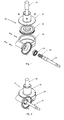
- Figure 1 shows, schematically, in perspective exploded, a reducer according to the invention.
- Figure 2 shows schematically, also in perspective, this same reducer, after assembly.
- Figure 3 shows, in a simplified way, a perspective rear side of a concrete mixer according to the invention, provided with a reducer also according to the invention, upon transmission of the rotational movement to the tank, and another reducer, also according to some of the characteristics of the invention, the transmission of the tilting movement to the arm tilting tank support, still allowing to identify areas corresponding to the amplifications represented in FIGS. 4 and 5.
- the perspective we took by frontal view the corresponding view to the placement of a worker facing the mouth of the tank.
- FIGS. 4 and 5 represent amplified perspective views, respectively, the area of the manual tilting handwheel of the tilting support arm of the tank and the area of the reducer and the motor for actuating the rotational movement of the tank around its axis.
- Figures 1 and 2 which represent a particular configuration of the gearbox (35) in question, it consists a body which, on one side, defines a motor connection flange (30) - visible in Figure 3 - and a seat for a bearing (34) for supporting the worm (38) which is the shaft (31) itself of the engine.
- the body (36) is open from the side the hollow toothed wheel (39), which is enveloped by this body but has no support point on this body, being fixed directly on the shaft (40) of the tank (4), this shaft being supported on the support (42) which serves simultaneously from cover to body.
- fixing the cover (42) to the body (36) is made by means of screws and the same happens to the fixing of the motor to said flange, which serves as a cover for the motor.
- the fixing of the motor (30) to the flange and the bearing (34) ensure the centering of the shaft / worm (31, 38), while centering the wheel hollow toothing is ensured by its placement in the tree (40).
- Figures 3 and 5 demonstrate the application of this reducer (35) on a concrete mixer (1).
- the reducer (35) is applied to the shaft (40) of the tank (4), being screwed to the support cube (42) of the shaft of the tank (4).
- This type of compact reducer applied to the concrete mixer, allows to eliminate, in an efficient and simple way, the classic transmission by pinion which has as disadvantages its operating noise and the danger of crushing, allowing easier certification of the product in the outline of community rules.
- This type of reducer can also be applied to tilting the tank (4), according to Figure 4, the arm shaft (3) being applied to the wheel hollow teeth and - in the case of manual actuation - the worm being linked to a steering wheel (or crank), either directly or, preferably, by means of a pair of bevel gears allowing the axis of rotation to be arranged of the steering wheel parallel to the tilting axis of said arm (3).
- This allows greater lightness during actuation, even in the case of actuation manual, as well as the elimination of the existing brake on concrete mixers traditional, thereby removing the risk associated with the incorrect manipulation of this.
Abstract
Description
La présente invention se rapporte à un réducteur mécanique de transmission de mouvement, notamment à un réducteur du type vis sans fin/roue à denture creuse.The present invention relates to a mechanical reduction gear transmission of movement, in particular to a reduction gear of the screwless type fine / hollow gear.
Malgré le fait que le réducteur, selon l'invention, puisse, d'une façon générale, être appliqué sur des plusieurs appareils distincts, il vise particulièrement l'application sur des bétonnières, sa conception ayant eu lieu de la nécessité de concevoir un réducteur pour une bétonnière. Alors, l'application sur les bétonnières des réducteurs selon l'invention intègre aussi l'invention.Despite the fact that the reducer according to the invention can, in a way general, be applied on several separate devices, it aims particularly the application on concrete mixers, its design having had instead of the need to design a reducer for a concrete mixer. So, the application to the concrete mixers of the reducers according to the invention also incorporates the invention.
Les réducteurs mécaniques de transmission de mouvement sont des appareils qui permettent de transformer un mouvement d'un composant mécanique (par exemple, un arbre), dans un mouvement d'un autre composant mécanique (par exemple, un autre arbre). Traditionnellement, ils sont employés pour convertir un mouvement de rotation dans un autre mouvement de rotation de vélocité angulaire inférieur, ces mouvements de rotation arrivant soit autour d'un axe, soit autour d'axes parallèles, soit autour d'axes obliques, soit encore autour d'axes orthogonaux. Ils sont des appareils mécaniques de transmission de mouvement qui trouvent très fréquemment leur application dans la comptabilisation des vélocités des organes moteurs (généralement élevées) au rapport aux vélocités plus basses requises par d'autres organes dans certains appareils.Mechanical motion transmission reducers are devices that transform a movement of a component mechanical (for example, a tree), in a movement of another mechanical component (for example, another tree). Traditionally, they are used to convert a rotational movement into another lower angular velocity rotation movement, these movements of rotation occurring either around an axis, or around parallel axes, or around oblique axes, or around orthogonal axes. They are devices motion transmission mechanics which are found very frequently their application in accounting for the velocities of the driving organs (generally high) compared to the lower velocities required by other organs in certain devices.
D'entre plusieurs types de réducteurs auxquels les mouvements de rotation dans l'arbre d'entrée et dans l'arbre de sortie arrivent sur des axes orthogonaux, ils sont connus des réducteurs qui utilisent une vis sans fin et une roue à denture creuse. Par chaque tour complète de la vis sans fin, la roue dentée avance un dent et, par conséquent, le rapport entre la vélocité d'entrée et la vélocité de sortie est égal au nombre des dents de la roue à denture creuse.Of several types of reducers to which the movements of rotation in the input shaft and in the output shaft arrive on axes orthogonal, they are known from reducers that use a worm and a hollow gear. By each complete turn of the worm, the toothed wheel advances a tooth and, therefore, the ratio of velocity input and output velocity is equal to the number of teeth of the wheel at hollow teeth.
Traditionnellement, ces réducteurs sont constitués d'un corps extérieur avec les liaisons d'entrée et de sortie effectuées au moyen d'arbres permettant d'être assemblés au moyen de liaisons extérieures à l'organe moteur et à l'organe extérieur à mouvementer. Autant la vis sans fin que la roue à denture creuse sont supportées dans le corps du réducteur au moyen de roulements ou de paliers d'appui afin de permettre l'alignement convenable de la vis sans fin et de la roue à denture creuse. Ces réducteurs disposent d'un couvercle à l'area de la roue dentée et d'un autre à l'area d'entrée de la vis sans fin, ces couvercles effectuant la clôture de tout le système.Traditionally, these reducers are made up of a body outdoor with input and output connections made by trees allowing to be assembled by means of connections external to the organ motor and to the external organ to be moved. Both the worm and the hollow gear wheels are supported in the body of the gearbox by means of bearings or support bearings to allow alignment suitable for the worm gear and the hollow gear. These reducers have a cover at the gear wheel area and another at the area of the auger, these covers closing all the system.
Les bétonnières sont des appareils qui permettent de préparer le béton, au moyen d'un mélange de leurs composants dans une cuve qui, pour l'effet, est mise à tourner, autour de son axe.Concrete mixers are devices that prepare the concrete, by means of a mixture of their components in a tank which, for the effect is set to rotate around its axis.
Particulièrement généralisées, notamment dans les travaux de construction civile de dimension intermédiaire - où il n'est pas rentable d'installer une centrale à béton, mais où la préparation manuelle est aussi complètement exclue en face des quantités déjà significatives de béton à préparer - ce sont les bétonnières mobiles, c'est-à-dire, bétonnières dont la cuve et les respectifs moyens d'actionnement se trouvent installés sur un bâti mobile, normalement doté de deux roues coaxiales, dans une extrémité, et d'un pieds d'appui, dans l'extrémité inverse.Particularly widespread, especially in the work of civil construction of intermediate size - where it is not profitable to install a concrete plant, but where manual preparation is also completely excluded in front of the already significant quantities of concrete to prepare - these are mobile concrete mixers, that is to say, concrete mixers whose tank and the respective actuation means are installed on a frame mobile, normally with two coaxial wheels at one end, and a support leg, in the opposite end.
Les bétonnières mobiles classiques disposent d'une configuration générale très typique, dont on remarque la couronne périmétrique dont la cuve est dotée extérieurement et qui est actionnée par un pignon moteur supporté par le bâti de la bétonnière, celui-ci supportant également un bras basculant en forme de "U" qui supporte la cuve, celle-ci étant fixée par son fond à celui-là, mais restant libre pour tourner autour de son axe quant elle est poussée par la respective couronne par l'action dudit pignon. Par l'action d'un volant qui actionne un ensemble de roues dentées, ce bras est mouvementé selon un mouvement basculant, en entraínant l'abaissement de l'embouchure de la cuve afin de faciliter le chargement de celle-ci ou de provoquer son déchargement par gravité, conforme le moindre ou le plus grand degré de basculement, respectivement, c'est-à-dire, le moindre ou le plus grand angle du mouvement basculant.Classic mobile concrete mixers have a configuration general very typical, of which we notice the perimeter crown whose tank is externally endowed and which is actuated by a drive pinion supported by the concrete mixer frame, which also supports an arm tilting in the shape of a "U" which supports the tank, the latter being fixed by its bottom to that one, but remaining free to turn around its axis when it is pushed by the respective crown by the action of said pinion. By action of a steering wheel which actuates a set of cogwheels, this arm is hectic in a rocking motion, causing the lowering of the mouth of the tank to facilitate loading of the tank or cause its unloading by gravity, conforms the least or the most great degree of tilting, respectively, i.e., the least or the largest angle of the tilting movement.
Ce type de bétonnières correspond, dans l'essentiel, à la bétonnière décrite à US55118198.This type of concrete mixer basically corresponds to the concrete mixer described in US55118198.
De même, dans la demande d'enregistrement du modèle d'utilité
décrit à FR2752391 A3 (avec priorité de 1996) on trouve une description
détaillée des bétonnières mobiles classiques (voyez: feuille 1, ligne 3 jusqu'à
la feuille 2, ligne 3, de la respective description), ainsi qu'une description des
respectifs inconvénients (voyez: feuille 2, ligne 4 jusqu'à la feuille 3, ligne 23
de la même description), comme l'haut bruit provoqué, notamment par
l'engrenage extérieur du pignon avec la couronne, les problèmes de sécurité
relatifs à cet engrenage extérieur, ainsi que les problèmes d'encombrement
arrivés. Selon la description y concernée, les inconvénients mentionnés
seraient éliminés ou diminués en utilisant, d'un côté, un réducteur assemblé
directement à la cuve et supporté sur le bras basculant et, d'autre côté, un
réducteur de roue à denture creuse-vis sans fin pour le basculement dudit
bras (et da la cuve correspondante) avec l'actionnement manuel (au moyen
d'une manivelle) ou avec l'actionnement motorisé. Il est prévu un réducteur
(R) à engrenages à bain d'huile pour l'actionnement de la cuve, lequel est
vissé sur le bras basculant et actionne la cuve au moyen d'un arbre de sortie
en forme conique qui se dépose sur un siège correspondant existant au fond
de la cuve est qui est vissée au bout de cet arbre. De préférence (voyez:
feuille 7, lignes 7 jusqu'à 9, de la description), le réducteur (R) sera du type
décrit dans la demande de brevet italien ITFI95 A 30. Ce réducteur
comprend deux pairs d'engrenages, étant doté d'un arbre intermédiaire placé
entre l'arbre d'entrée et l'arbre de sortie, étant cet arbre intermédiaire, au
moins, supporté à l'intérieur du corps du réducteur.Similarly, in the application for registration of the utility model
described in FR2752391 A3 (with priority from 1996) there is a description
detail of conventional mobile concrete mixers (see:
De plus, l'abordage d'inclure l'organe moteur dans le bras
basculant, afin d'éliminer la dite couronne, était déjà connu antérieurement
(au moins depuis 1990), étant référée à propos de la définition de
l'arrière-plan technologique comme décrit au brevet US5190372. Le
problème technique y concerné se rapportait surtout à l'adoption d'une
solution qui permettait d'éviter le placement du moteur sur le bras basculant
du côté contraire à celui de la cuve, en évitant de cette façon le risque de
choc accidentel, au moment du mouvement de basculement du bras, des
éléments de l'organe moteur contre un chariot placé sous la cuve, en se
lésant (voyez: colonne 1, lignes 25 jusqu'à 31). La solution de ce problème se
faisait soit par l'application de l'organe moteur à l'intérieur de la cuve (voyez:
figure 3), soit par le placement de l'organe moteur sur le bras basculant, mais
placé vers le côté de la cuve (voyez: figure 2), en utilisant une transmission
par courroie. Dans les deux cas, la transmission prévoyait un réducteur placé
dans la cuve, ayant ce réducteur une transmission épicycloïdale et en
particulier planocentrique (voyez colonne 2, lignes 14 jusqu'à 22).In addition, the boarding to include the motor organ in the arm
tilting, in order to eliminate the said crown, was already known previously
(at least since 1990), being referred to in connection with the definition of
the technological background as described in patent US5190372. The
technical problem concerned related mainly to the adoption of a
solution which made it possible to avoid placing the motor on the rocking arm
on the opposite side to that of the tank, thereby avoiding the risk of
accidental shock, during the tilting movement of the arm,
elements of the drive unit against a carriage placed under the tank,
aggressor (see:
Malgré le fait que la déposante dudit modèle d'utilité français ne se rapporte pas, dans le document correspondant; à ce problème, elle l'a eut, certainement, en considération, car on vérifie que postérieurement elle a déposé le modèle d'utilité publié sous FR2803557 (avec priorité de 2000), lequel a suivi une philosophie pareille à celle dudit brevet américain US5190372, sauf en ce qui concerne la circonstance que le réducteur n'est pas partiellement placé dans le tambour, certes afin d'éviter un des inconvénients du dispositif de ce même brevet US5190372, c'est-à-dire, le gaspillage du volume utile de la cuve, lequel, afin d'être minimisé, a impliqué le recours à la transmission épicycloïdale mentionnée.Despite the fact that the applicant for said French utility model did not not report in the corresponding document; to this problem, she had it, certainly, in consideration, because we check that later it has registered the utility model published under FR2803557 (with priority of 2000), which followed a philosophy similar to that of said American patent US5190372, except for the circumstance that the reducer is not not partially placed in the drum, certainly to avoid one of the disadvantages of the device of this same patent US5190372, that is to say, the waste of the useful volume of the tank, which, in order to be minimized, involved the use of the epicyclic transmission mentioned.
Un des buts de la présente invention vise une bétonnière à laquelle la transmission du mouvement de l'organe moteur vers la cuve soit faite sans recours à aucune couronne extérieure dans la cuve et à laquelle la liaison de cet organe moteur soit faite directement au réducteur d'actionnement de la cuve, sans aucunes courroies ou poulies, en visant, de même, un réducteur à profil très bas et muni d'une telle orientation des arbres d'entrée et de sortie que le moteur et le réducteur restent très proches du bout de la cuve et n'augment pas significativement le risque de collision, lors du basculement de la cuve de la bétonnière, notamment avec un chariot qu'on trouve sous la cuve.One of the aims of the present invention relates to a concrete mixer to which the transmission of the movement of the motor member to the tank is made without use of no external crown in the tank and to which the connection of this drive member is made directly to the actuation reducer of the tank, without any belts or pulleys, aiming, likewise, a reducer to very low profile and with such an orientation of the input and output shafts that the motor and the gearbox remain very close to the end of the tank and does not significantly increase the risk of collision when tilting the concrete mixer tank, especially with a trolley that is found under the tank.
Un autre but, d'ailleurs rapporté au bas profil du réducteur, c'est que celui-ci aie une constitution trop simple et un nombre de composants très bas, notamment en partageant plusieurs éléments avec le moteur et avec l'organe à actionner, étant, alors, très compact.Another goal, also related to the low profile of the reducer, is that this one has too simple a constitution and a number of components very low, especially by sharing several elements with the engine and with the member to be actuated, being, then, very compact.
D'autres buts découleront de la lecture de la présente description, ainsi que des revendications.Other purposes will result from reading this description, as well as claims.
Selon la présente invention les buts sont atteints au moyen d'un réducteur de transmission mécanique - comprenant un corps, une vis sans fin et une roue à denture creuse - qui se caractérise par ne posséder, lui-même, aucun arbre ou aucun roulement ou palier, l'arbre de support de la vis sans fin étant l'arbre du moteur (30) et l'arbre de la roue à denture creuse étant l'arbre de l'organe extérieur à actionner, lequel, au cas des bétonnières, est l'arbre de la cuve.According to the present invention the objects are achieved by means of a mechanical transmission reducer - comprising a body, a screw end and a hollow gear - which is characterized by not having, itself, no shaft or any bearing or bearing, the support shaft of the worm being the motor shaft (30) and the hollow gear wheel shaft being the shaft of the external member to be actuated, which, in the case of concrete mixers, is the shaft of the tank.
Alors, au réducteur selon l'invention, la roue à denture creuse n'est pas supportée sur le corps, celui-ci étant ouvert du côté de la dite roue à denture creuse et le support de l'arbre de l'organe extérieur à actionner servant de couvercle au corps mentionné, en étanchant le réducteur.Then, with the reduction gear according to the invention, the hollow toothed wheel is not not supported on the body, the latter being open on the side of the said wheel hollow teeth and the shaft support of the external member to be actuated serving as a cover for the body mentioned, by sealing the reducer.
En outre, au réducteur selon l'invention, le corps n'est pourvu que d'un point d'appui pour un roulement d'appui de l'arbre du moteur/vis sans fin et ledit corps est pourvu d'une bride de liaison au moteur, cette bride remplaçant le traditionnel couvercle du moteur.In addition, with the reducer according to the invention, the body is only provided a fulcrum for a bearing supporting the motor shaft / worm and said body is provided with a motor connection flange, this flange replacing the traditional engine cover.
La bétonnière se caractérise en ce qu'elle a un réducteur comme déjà décrit, monté sur la partie centrale de son bras basculant - en forme de «U» - et directement lié à l'arbre de la cuve.The concrete mixer is characterized in that it has a reducer like already described, mounted on the central part of its tilting arm - shaped "U" - and directly linked to the shaft of the tank.
Selon une forme préférée d'exécution de la présente invention, le moteur assume une position substantiellement parallèle à la partie centrale du bras en forme de «U».According to a preferred embodiment of the present invention, the motor assumes a position substantially parallel to the central part "U" shaped arm.
En face des caractéristiques du réducteur de l'invention, on vérifie qu'il est plus compact, notamment au niveau du corps, que les traditionnels et qu'il dispose d'un nombre plus petit de pièces mobiles et, alors, d'un nombre plus petit de pièces sujettes à la consumation, et qu'il dispose encore d'un nombre plus petit de points de machination. De plus, il ne nécessite pas d'éléments autonomes, notamment d'accouplements individuels, soit à la liaison à l'organe moteur, soit à la liaison à l'organe à actionner. Tout cela se traduit par un moindre coût de production et de montage. A son tour, la bétonnière selon l'invention, en jouissant de ces avantages, permet l'actionnement direct de la cuve sans nécessité d'une couronne et si peu d'une courroie ou d'un élément équivalent de transmission du moteur vers le réducteur, sans, pourtant, augmenter significativement le risque de collision, lors du basculement de la cuve, entre ce moteur ou le réducteur et les objets qui se trouvent proches de la bétonnière, notamment un chariot resté au-dessous ce celle-ci.In front of the characteristics of the reducer of the invention, we check that it is more compact, especially in terms of the body, than traditional and that it has a smaller number of moving parts and then a number smaller parts subject to consumption, and that it still has a smaller number of machining points. In addition, it does not require autonomous elements, in particular individual couplings, either at the connection to the motor member, or to the connection to the member to be actuated. All of this results in lower production and assembly costs. In turn, the concrete mixer according to the invention, by enjoying these advantages, allows direct actuation of the tank without the need for a crown and so little a belt or equivalent element for transmitting the engine to the reducing, without, however, significantly increasing the risk of collision, during the tilting of the tank, between this motor or the reducer and the objects which are close to the concrete mixer, in particular a carriage which has remained below this one.
Les figures en annexe, présentées à titre simplement illustratif et pas limitatif, permettent de mieux comprendre la présente invention, ainsi que les principales différences par rapport à une solution de l'arrière-plan de la technique.The attached figures, presented for illustrative purposes only and not limiting, allow a better understanding of the present invention, as well as the main differences from a background solution of the technical.
La figure 1 représente, d'une façon schématique, en perspective explosée, un réducteur selon l'invention.Figure 1 shows, schematically, in perspective exploded, a reducer according to the invention.
La figure 2 représente schématiquement, aussi en perspective, ce même réducteur, après le montage.Figure 2 shows schematically, also in perspective, this same reducer, after assembly.
La figure 3 représente, d'une façon simplifiée, une perspective latérale postérieure d'une bétonnière selon l'invention, munie d'un réducteur également selon l'invention, à la transmission du mouvement de rotation à la cuve, et d'un autre réducteur, aussi selon quelques-unes des caractéristiques de l'invention, à la transmission du mouvement de basculement au bras basculant de support de la cuve, en permettant encore d'identifier les areas correspondantes aux ampliations représentées aux figures 4 et 5. Dans la désignation de la perspective on a pris par vue frontale la vue correspondante au placement d'un ouvrier tourné vis-à-vis l'embouchure de la cuve.Figure 3 shows, in a simplified way, a perspective rear side of a concrete mixer according to the invention, provided with a reducer also according to the invention, upon transmission of the rotational movement to the tank, and another reducer, also according to some of the characteristics of the invention, the transmission of the tilting movement to the arm tilting tank support, still allowing to identify areas corresponding to the amplifications represented in FIGS. 4 and 5. In the designation of the perspective we took by frontal view the corresponding view to the placement of a worker facing the mouth of the tank.
Les figures 4 et 5 représentent des vues amplifiées en perspective, respectivement, de l'area du volant d'actionnement manuel du basculement du bras basculant de support de la cuve et de l'area du réducteur et du moteur d'actionnement du mouvement de rotation de la cuve autour de son axe.FIGS. 4 and 5 represent amplified perspective views, respectively, the area of the manual tilting handwheel of the tilting support arm of the tank and the area of the reducer and the motor for actuating the rotational movement of the tank around its axis.
La description complémentaire de l'invention est maintenant faite avec référence aux figures citées, où les divers éléments se trouvent référenciés de la façon suivante:
Bétonnière 1;Bâti 2;- Bras basculant 3;
Moteur 30;- Arbre 31;
Roulement 34 ;Réducteur 35;Corps 36;- Vis sans
fin 38; - Roue à denture creuse 39;
- Cuve/organe extérieur à actionner 4;
Arbre 40;- Couvercle/
support 42.
-
Concrete mixer 1; -
Frame 2; - Rocking
arm 3;-
Motor 30; -
Tree 31; -
Bearing 34; -
Reducer 35; -
Body 36; -
Worm 38; -
Hollow gear 39;
-
- Tank / external member to be operated 4;
-
Tree 40; - Cover /
holder 42.
-
Comme on vérifie au moyen des figures 1 et 2 qui représentent une configuration particulaire du réducteur (35) en cause, celui-ci est constitué d'un corps qui, d'un côté, définit une bride de liaison au moteur (30) - visible à la figure 3 - et un siège pour un roulement (34) d'appui de la vis sans fin (38) qui est l'arbre (31) lui-même du moteur. Le corps (36) est ouvert du côté de la roue à denture creuse (39), laquelle est enveloppée par ce corps mais ne dispose d'aucun point d'appui sur ce corps, étant fixée directement sur l'arbre (40) de la cuve (4), cet arbre étant soutenu sur le support (42) qui sert simultanément de couvercle au corps. De préférence, la fixation du couvercle (42) au corps (36) est faite au moyen de vis et le même arrive à la fixation du moteur à ladite bride, laquelle sert comme couvercle au moteur.As we verify by means of Figures 1 and 2 which represent a particular configuration of the gearbox (35) in question, it consists a body which, on one side, defines a motor connection flange (30) - visible in Figure 3 - and a seat for a bearing (34) for supporting the worm (38) which is the shaft (31) itself of the engine. The body (36) is open from the side the hollow toothed wheel (39), which is enveloped by this body but has no support point on this body, being fixed directly on the shaft (40) of the tank (4), this shaft being supported on the support (42) which serves simultaneously from cover to body. Preferably fixing the cover (42) to the body (36) is made by means of screws and the same happens to the fixing of the motor to said flange, which serves as a cover for the motor.
La fixation du moteur (30) à la bride et le roulement (34) assurent le centrage de l'arbre/vis sans fin (31, 38), pendant que le centrage de la roue à denture creuse est assuré par son placage dans l'arbre (40).The fixing of the motor (30) to the flange and the bearing (34) ensure the centering of the shaft / worm (31, 38), while centering the wheel hollow toothing is ensured by its placement in the tree (40).
A son tour, les figures 3 et 5 démontrent l'application de ce réducteur (35) sur une bétonnière (1).In turn, Figures 3 and 5 demonstrate the application of this reducer (35) on a concrete mixer (1).
Sur une bétonnière, l'application de ce type de réducteur (35) au mouvement de la cuve est spécialement indiquée, due à son bas poids et forme compacte.On a concrete mixer, the application of this type of reducer (35) to movement of the tank is specially indicated, due to its low weight and compact shape.
Le réducteur (35) est appliqué sur l'arbre (40) de la cuve (4), étant vissé au cube de support (42) de l'arbre de la cuve (4).The reducer (35) is applied to the shaft (40) of the tank (4), being screwed to the support cube (42) of the shaft of the tank (4).
Sans préjudice de que le réducteur du type mentionné puisse être utilisé dans d'autres types d'applications ou d'appareils, il se trouve bien adapté à l'application concrète sur les bétonnières, soit en termes des efforts à subir, soit en termes de l'adéquation aux vélocités typiques d'entrée et de sortie, de l'ordre de 1500rpm environ sur celle-là et de 25rpm environ sur celle-ci, laquelle constitue la vélocité idéale au mélange du béton sur des cuves de la grandeur traditionnelle dans ce type de bétonnières.Without prejudice to the fact that the reduction gear of the type mentioned may be used in other types of apps or devices it sits well adapted to the concrete application on concrete mixers, in terms of efforts to undergo, either in terms of the adequacy at the typical velocities of entry and output, around 1500rpm on this one and around 25rpm on this this, which constitutes the ideal velocity for mixing concrete on tanks of traditional greatness in this type of concrete mixers.
Ce type de réducteur compact, appliqué sur la bétonnière, permet d'éliminer, d'une façon efficace et simple, la classique transmission par pignon qui a comme inconvénients son bruit de fonctionnement et le danger d'écrasement, en permettant une plus facile certification du produit dans le contour des règles communautaires.This type of compact reducer, applied to the concrete mixer, allows to eliminate, in an efficient and simple way, the classic transmission by pinion which has as disadvantages its operating noise and the danger of crushing, allowing easier certification of the product in the outline of community rules.
Ce type de réducteur peut aussi être appliqué au basculement de la cuve (4), selon la figure 4, l'arbre du bras (3) étant appliqué sur la roue à denture creuse et - au cas de l'actionnement manuel - la vis sans fin étant liée à un volant (ou manivelle), soit directement, soit, de préférence, au moyen d'un pair de pignons coniques permettant de disposer l'axe de rotation du volant parallèlement à l'axe de basculement dudit bras (3). Cela permet une plus grande légèreté à l'actionnement, même au cas de l'actionnement manuel, ainsi que l'élimination du frein existant sur les bétonnières traditionnelles, en supprimant, de cette façon, le risque associé à l'incorrecte manipulation de ceci.This type of reducer can also be applied to tilting the tank (4), according to Figure 4, the arm shaft (3) being applied to the wheel hollow teeth and - in the case of manual actuation - the worm being linked to a steering wheel (or crank), either directly or, preferably, by means of a pair of bevel gears allowing the axis of rotation to be arranged of the steering wheel parallel to the tilting axis of said arm (3). This allows greater lightness during actuation, even in the case of actuation manual, as well as the elimination of the existing brake on concrete mixers traditional, thereby removing the risk associated with the incorrect manipulation of this.
Malgré le fait que dans l'exemple décrit, le sans fin (38) et l'arbre (31) du moteur (30) soient un seul composant, il est manifeste qu'il pourrait s'agir de deux pièces distinctes, la vis sans fin étant liée à l'arbre dudit moteur, selon quelque méthode conventionnel.Despite the fact that in the example described, the endless (38) and the tree (31) of the motor (30) are a single component, it is obvious that it could be two separate parts, the worm being linked to the shaft of said engine, by some conventional method.
Malgré le fait que le réducteur selon l'invention aie provenu d'une conception motivé par une application concrète sur des bétonnières, les caractéristiques de simplicité et le caractère compact de ce réducteur le rendent aussi adéquat à l'application sur d'autre type d'appareils, où on exige une transmission mécanique avec réduction de vélocité, étant le dimensionnement en termes de puissance et de vélocités d'entrée et de sortie des tâches manifestement du domaine des connaissances générales de l'homme du métier.Despite the fact that the reducer according to the invention came from a design motivated by a concrete application on concrete mixers, simplicity features and compactness of this reducer the also make it suitable for application on other types of devices, where it is required a mechanical transmission with velocity reduction, being the dimensioning in terms of power and input velocities and leaving tasks clearly in the realm of general knowledge of the skilled person.
Claims (8)
Applications Claiming Priority (2)
| Application Number | Priority Date | Filing Date | Title |
|---|---|---|---|
| PT10278002 | 2002-05-20 | ||
| PT10278002A PT102780B (en) | 2002-05-20 | 2002-05-20 | TRANSMISSION REDUCER AND ITS APPLICATION |
Publications (2)
| Publication Number | Publication Date |
|---|---|
| EP1365171A2 true EP1365171A2 (en) | 2003-11-26 |
| EP1365171A3 EP1365171A3 (en) | 2004-09-29 |
Family
ID=20086108
Family Applications (1)
| Application Number | Title | Priority Date | Filing Date |
|---|---|---|---|
| EP03011429A Withdrawn EP1365171A3 (en) | 2002-05-20 | 2003-05-20 | Worm gear transmission for cement mixer |
Country Status (2)
| Country | Link |
|---|---|
| EP (1) | EP1365171A3 (en) |
| PT (1) | PT102780B (en) |
Cited By (2)
| Publication number | Priority date | Publication date | Assignee | Title |
|---|---|---|---|---|
| CN104613130A (en) * | 2015-01-28 | 2015-05-13 | 周正英 | Turbine and worm reducer |
| CN106346612A (en) * | 2016-09-07 | 2017-01-25 | 江苏大学 | Lifting vibration type cement mortar agitation mechanism |
Families Citing this family (1)
| Publication number | Priority date | Publication date | Assignee | Title |
|---|---|---|---|---|
| CN109159297A (en) * | 2018-10-29 | 2019-01-08 | 长安大学 | A kind of conjuncted cartridge type upright shaft stirring machine of double worm gear list worm-drive |
Citations (8)
| Publication number | Priority date | Publication date | Assignee | Title |
|---|---|---|---|---|
| GB127560A (en) * | 1918-05-29 | 1920-01-29 | Nathan Clarke Johnson | Improvements relating to the Mixing of Cement and Apparatus therefor. |
| DE871720C (en) * | 1950-11-13 | 1953-03-26 | Urpo Ristola | Mixer for concrete and similar building materials |
| GB718945A (en) * | 1952-01-29 | 1954-11-24 | Bishop Arthur E | Improved concrete mixer |
| CH365320A (en) * | 1959-03-26 | 1962-10-31 | Stothert & Pitt Ltd | Cement mixer |
| FR2748436A1 (en) * | 1996-05-07 | 1997-11-14 | Valeo Systemes Dessuyage | Electric motor and gearing assembly for motor vehicle windscreen wipers |
| FR2752391A3 (en) * | 1996-06-14 | 1998-02-20 | Imer Int Spa | Concrete mixer |
| US5836219A (en) * | 1995-08-25 | 1998-11-17 | Siemens Aktiengesellshcaft | Gear-case arrangement for a motor-gear drive unit, in particular for automobile window lifters or the like |
| FR2803557A3 (en) * | 2000-01-11 | 2001-07-13 | Imer Internat Spa | Concrete mixer has arm supporting drum rotated around axis forming pivot for drum |
-
2002
- 2002-05-20 PT PT10278002A patent/PT102780B/en not_active IP Right Cessation
-
2003
- 2003-05-20 EP EP03011429A patent/EP1365171A3/en not_active Withdrawn
Patent Citations (8)
| Publication number | Priority date | Publication date | Assignee | Title |
|---|---|---|---|---|
| GB127560A (en) * | 1918-05-29 | 1920-01-29 | Nathan Clarke Johnson | Improvements relating to the Mixing of Cement and Apparatus therefor. |
| DE871720C (en) * | 1950-11-13 | 1953-03-26 | Urpo Ristola | Mixer for concrete and similar building materials |
| GB718945A (en) * | 1952-01-29 | 1954-11-24 | Bishop Arthur E | Improved concrete mixer |
| CH365320A (en) * | 1959-03-26 | 1962-10-31 | Stothert & Pitt Ltd | Cement mixer |
| US5836219A (en) * | 1995-08-25 | 1998-11-17 | Siemens Aktiengesellshcaft | Gear-case arrangement for a motor-gear drive unit, in particular for automobile window lifters or the like |
| FR2748436A1 (en) * | 1996-05-07 | 1997-11-14 | Valeo Systemes Dessuyage | Electric motor and gearing assembly for motor vehicle windscreen wipers |
| FR2752391A3 (en) * | 1996-06-14 | 1998-02-20 | Imer Int Spa | Concrete mixer |
| FR2803557A3 (en) * | 2000-01-11 | 2001-07-13 | Imer Internat Spa | Concrete mixer has arm supporting drum rotated around axis forming pivot for drum |
Cited By (2)
| Publication number | Priority date | Publication date | Assignee | Title |
|---|---|---|---|---|
| CN104613130A (en) * | 2015-01-28 | 2015-05-13 | 周正英 | Turbine and worm reducer |
| CN106346612A (en) * | 2016-09-07 | 2017-01-25 | 江苏大学 | Lifting vibration type cement mortar agitation mechanism |
Also Published As
| Publication number | Publication date |
|---|---|
| EP1365171A3 (en) | 2004-09-29 |
| PT102780A (en) | 2003-01-31 |
| PT102780B (en) | 2004-10-29 |
Similar Documents
| Publication | Publication Date | Title |
|---|---|---|
| FR2492027A1 (en) | METHOD FOR MOUNTING A WHEEL DRIVE AND DOUBLE KINEMATICS CHAIN AND MOTOR REDUCER THEREFOR | |
| EP1365171A2 (en) | Worm gear transmission for cement mixer | |
| EP0004230A1 (en) | Device for controlling and checking the tilting of a vehicle's bodywork | |
| FR3042569A1 (en) | GEARBOX FOR MOTORCYCLE EQUIPMENT AND MOTORCYCLE EQUIPMENT COMPRISING SUCH A GEARBOX. | |
| EP0730991B2 (en) | Gearbox | |
| FR2558233A1 (en) | MULTI-RANGE DRIVE AXLE ASSEMBLY FOR A MOTOR VEHICLE | |
| FR2636894A1 (en) | TRANSFORMATION ASSEMBLY OF A TWO-WHEEL DRIVE VEHICLE INTO A FOUR-DRIVE VEHICLE | |
| FR2892168A1 (en) | GEARBOX FOR MOTOCULTURE EQUIPMENT | |
| FR2561341A1 (en) | SPEED REDUCER WITH BALANCED AXIAL AND CROSS-SECTIONAL COMPONENTS | |
| FR2726619A1 (en) | Vehicle gearbox with two secondary shafts for use with transverse mounted engines | |
| EP1097317B1 (en) | Transmission unit with reversing mechanism mounted between a gearbox and at least two drive wheels | |
| CH277293A (en) | Mixer. | |
| FR2542806A1 (en) | DEVICE FOR DRIVING THE CAMSHAFT OF AN INTERNAL COMBUSTION ENGINE | |
| FR2754035A1 (en) | Differential transmission for front wheel drive motor vehicles | |
| FR2757239A1 (en) | Reciprocating IC engine camshaft transmission balancing system | |
| FR2812843A1 (en) | CARRIER CARRIER DRIVE UNIT | |
| FR2688556A1 (en) | DRIVE COUPLING SYSTEM FOR ROTATING THE ROTARY MEMBER OF A WORKING DEVICE FOR A BEARING VEHICLE. | |
| FR2543641A1 (en) | GEAR SPEED REDUCER, ESPECIALLY FOR TELEPHERIC, OR THE LIKE | |
| EP0001366A1 (en) | Simplified fore-axle with two drive wheels for automotive vehicle | |
| FR2711720A1 (en) | Angle return device for rolling shutter. | |
| FR2555274A1 (en) | Transmission joint with bevel gears | |
| FR2535577A1 (en) | Device for driving a dough mixing arm | |
| FR2624668A1 (en) | ELECTRIC TRANSMISSION MOTOR | |
| FR2791407A1 (en) | Automatic multispeed transmission for road vehicle has two gearboxes with epicyclic gearing connected in series to give large number of ratio changes | |
| FR2674812A3 (en) | Transmission mechanism structure for bicycles |
Legal Events
| Date | Code | Title | Description |
|---|---|---|---|
| PUAI | Public reference made under article 153(3) epc to a published international application that has entered the european phase |
Free format text: ORIGINAL CODE: 0009012 |
|
| AK | Designated contracting states |
Kind code of ref document: A2 Designated state(s): AT BE BG CH CY CZ DE DK EE ES FI FR GB GR HU IE IT LI LU MC NL PT RO SE SI SK TR |
|
| AX | Request for extension of the european patent |
Extension state: AL LT LV MK |
|
| PUAL | Search report despatched |
Free format text: ORIGINAL CODE: 0009013 |
|
| AK | Designated contracting states |
Kind code of ref document: A3 Designated state(s): AT BE BG CH CY CZ DE DK EE ES FI FR GB GR HU IE IT LI LU MC NL PT RO SE SI SK TR |
|
| AX | Request for extension of the european patent |
Extension state: AL LT LV MK |
|
| RIC1 | Information provided on ipc code assigned before grant |
Ipc: 7B 28C 5/26 - Ipc: 7B 28C 5/08 B Ipc: 7F 16H 57/02 B Ipc: 7F 16H 1/16 A |
|
| 17P | Request for examination filed |
Effective date: 20050328 |
|
| AKX | Designation fees paid |
Designated state(s): AT BE BG CH CY CZ DE DK EE ES FI FR GB GR HU IE IT LI LU MC NL PT RO SE SI SK TR |
|
| 17Q | First examination report despatched |
Effective date: 20050623 |
|
| STAA | Information on the status of an ep patent application or granted ep patent |
Free format text: STATUS: THE APPLICATION IS DEEMED TO BE WITHDRAWN |
|
| 18D | Application deemed to be withdrawn |
Effective date: 20060708 |