EP1365171A2 - Réducteur de transmission mécanique à vis sans fin pour bétonnière - Google Patents
Réducteur de transmission mécanique à vis sans fin pour bétonnière Download PDFInfo
- Publication number
- EP1365171A2 EP1365171A2 EP03011429A EP03011429A EP1365171A2 EP 1365171 A2 EP1365171 A2 EP 1365171A2 EP 03011429 A EP03011429 A EP 03011429A EP 03011429 A EP03011429 A EP 03011429A EP 1365171 A2 EP1365171 A2 EP 1365171A2
- Authority
- EP
- European Patent Office
- Prior art keywords
- shaft
- reducer
- motor
- tank
- worm
- Prior art date
- Legal status (The legal status is an assumption and is not a legal conclusion. Google has not performed a legal analysis and makes no representation as to the accuracy of the status listed.)
- Withdrawn
Links
Images

Classifications
-
- F—MECHANICAL ENGINEERING; LIGHTING; HEATING; WEAPONS; BLASTING
- F16—ENGINEERING ELEMENTS AND UNITS; GENERAL MEASURES FOR PRODUCING AND MAINTAINING EFFECTIVE FUNCTIONING OF MACHINES OR INSTALLATIONS; THERMAL INSULATION IN GENERAL
- F16H—GEARING
- F16H57/00—General details of gearing
- F16H57/02—Gearboxes; Mounting gearing therein
- F16H57/039—Gearboxes for accommodating worm gears
-
- B—PERFORMING OPERATIONS; TRANSPORTING
- B28—WORKING CEMENT, CLAY, OR STONE
- B28C—PREPARING CLAY; PRODUCING MIXTURES CONTAINING CLAY OR CEMENTITIOUS MATERIAL, e.g. PLASTER
- B28C5/00—Apparatus or methods for producing mixtures of cement with other substances, e.g. slurries, mortars, porous or fibrous compositions
- B28C5/08—Apparatus or methods for producing mixtures of cement with other substances, e.g. slurries, mortars, porous or fibrous compositions using driven mechanical means affecting the mixing
- B28C5/0806—Details; Accessories
- B28C5/0831—Drives or drive systems, e.g. toothed racks, winches
- B28C5/0837—Drives for mixers of the tilted-drum type
-
- F—MECHANICAL ENGINEERING; LIGHTING; HEATING; WEAPONS; BLASTING
- F16—ENGINEERING ELEMENTS AND UNITS; GENERAL MEASURES FOR PRODUCING AND MAINTAINING EFFECTIVE FUNCTIONING OF MACHINES OR INSTALLATIONS; THERMAL INSULATION IN GENERAL
- F16H—GEARING
- F16H1/00—Toothed gearings for conveying rotary motion
- F16H1/02—Toothed gearings for conveying rotary motion without gears having orbital motion
- F16H1/04—Toothed gearings for conveying rotary motion without gears having orbital motion involving only two intermeshing members
- F16H1/12—Toothed gearings for conveying rotary motion without gears having orbital motion involving only two intermeshing members with non-parallel axes
- F16H1/16—Toothed gearings for conveying rotary motion without gears having orbital motion involving only two intermeshing members with non-parallel axes comprising worm and worm-wheel
-
- F—MECHANICAL ENGINEERING; LIGHTING; HEATING; WEAPONS; BLASTING
- F16—ENGINEERING ELEMENTS AND UNITS; GENERAL MEASURES FOR PRODUCING AND MAINTAINING EFFECTIVE FUNCTIONING OF MACHINES OR INSTALLATIONS; THERMAL INSULATION IN GENERAL
- F16H—GEARING
- F16H57/00—General details of gearing
- F16H57/02—Gearboxes; Mounting gearing therein
- F16H2057/02039—Gearboxes for particular applications
- F16H2057/02069—Gearboxes for particular applications for industrial applications
- F16H2057/02073—Reduction gearboxes for industry
-
- F—MECHANICAL ENGINEERING; LIGHTING; HEATING; WEAPONS; BLASTING
- F16—ENGINEERING ELEMENTS AND UNITS; GENERAL MEASURES FOR PRODUCING AND MAINTAINING EFFECTIVE FUNCTIONING OF MACHINES OR INSTALLATIONS; THERMAL INSULATION IN GENERAL
- F16H—GEARING
- F16H57/00—General details of gearing
- F16H57/02—Gearboxes; Mounting gearing therein
- F16H2057/02086—Measures for reducing size of gearbox, e.g. for creating a more compact transmission casing
-
- F—MECHANICAL ENGINEERING; LIGHTING; HEATING; WEAPONS; BLASTING
- F16—ENGINEERING ELEMENTS AND UNITS; GENERAL MEASURES FOR PRODUCING AND MAINTAINING EFFECTIVE FUNCTIONING OF MACHINES OR INSTALLATIONS; THERMAL INSULATION IN GENERAL
- F16H—GEARING
- F16H57/00—General details of gearing
- F16H57/02—Gearboxes; Mounting gearing therein
- F16H2057/02095—Measures for reducing number of parts or components
-
- F—MECHANICAL ENGINEERING; LIGHTING; HEATING; WEAPONS; BLASTING
- F16—ENGINEERING ELEMENTS AND UNITS; GENERAL MEASURES FOR PRODUCING AND MAINTAINING EFFECTIVE FUNCTIONING OF MACHINES OR INSTALLATIONS; THERMAL INSULATION IN GENERAL
- F16H—GEARING
- F16H57/00—General details of gearing
- F16H57/02—Gearboxes; Mounting gearing therein
- F16H57/021—Shaft support structures, e.g. partition walls, bearing eyes, casing walls or covers with bearings
- F16H2057/0213—Support of worm gear shafts
Definitions
- the present invention relates to a mechanical reduction gear transmission of movement, in particular to a reduction gear of the screwless type fine / hollow gear.
- the reducer according to the invention can, in a way general, be applied on several separate devices, it aims particularly the application on concrete mixers, its design having had instead of the need to design a reducer for a concrete mixer. So, the application to the concrete mixers of the reducers according to the invention also incorporates the invention.
- Mechanical motion transmission reducers are devices that transform a movement of a component mechanical (for example, a tree), in a movement of another mechanical component (for example, another tree). Traditionally, they are used to convert a rotational movement into another lower angular velocity rotation movement, these movements of rotation occurring either around an axis, or around parallel axes, or around oblique axes, or around orthogonal axes. They are devices motion transmission mechanics which are found very frequently their application in accounting for the velocities of the driving organs (generally high) compared to the lower velocities required by other organs in certain devices.
- reducers To which the movements of rotation in the input shaft and in the output shaft arrive on axes orthogonal, they are known from reducers that use a worm and a hollow gear. By each complete turn of the worm, the toothed wheel advances a tooth and, therefore, the ratio of velocity input and output velocity is equal to the number of teeth of the wheel at hollow teeth.
- these reducers are made up of a body outdoor with input and output connections made by trees allowing to be assembled by means of connections external to the organ motor and to the external organ to be moved. Both the worm and the hollow gear wheels are supported in the body of the gearbox by means of bearings or support bearings to allow alignment suitable for the worm gear and the hollow gear. These reducers have a cover at the gear wheel area and another at the area of the auger, these covers closing all the system.
- Concrete mixers are devices that prepare the concrete, by means of a mixture of their components in a tank which, for the effect is set to rotate around its axis.
- Classic mobile concrete mixers have a configuration general very typical, of which we notice the perimeter crown whose tank is externally endowed and which is actuated by a drive pinion supported by the concrete mixer frame, which also supports an arm tilting in the shape of a "U" which supports the tank, the latter being fixed by its bottom to that one, but remaining free to turn around its axis when it is pushed by the respective crown by the action of said pinion.
- this arm By action of a steering wheel which actuates a set of cogwheels, this arm is strictly in a rocking motion, causing the lowering of the mouth of the tank to facilitate loading of the tank or cause its unloading by gravity, conforms the least or the most great degree of tilting, respectively, i.e., the least or the largest angle of the tilting movement.
- This type of concrete mixer basically corresponds to the concrete mixer described in US55118198.
- the reducer (R) will be of the type described in Italian patent application ITFI95 A 30.
- This reducer includes two pairs of gears, having an intermediate shaft placed between the input shaft and the output shaft, being this intermediate shaft, at less, supported inside the body of the reducer.
- One of the aims of the present invention relates to a concrete mixer to which the transmission of the movement of the motor member to the tank is made without use of no external crown in the tank and to which the connection of this drive member is made directly to the actuation reducer of the tank, without any belts or pulleys, aiming, likewise, a reducer to very low profile and with such an orientation of the input and output shafts that the motor and the gearbox remain very close to the end of the tank and does not significantly increase the risk of collision when tilting the concrete mixer tank, especially with a trolley that is found under the tank.
- Another goal, also related to the low profile of the reducer, is that this one has too simple a constitution and a number of components very low, especially by sharing several elements with the engine and with the member to be actuated, being, then, very compact.
- a mechanical transmission reducer - comprising a body, a screw end and a hollow gear - which is characterized by not having, itself, no shaft or any bearing or bearing, the support shaft of the worm being the motor shaft (30) and the hollow gear wheel shaft being the shaft of the external member to be actuated, which, in the case of concrete mixers, is the shaft of the tank.
- the hollow toothed wheel is not not supported on the body, the latter being open on the side of the said wheel hollow teeth and the shaft support of the external member to be actuated serving as a cover for the body mentioned, by sealing the reducer.
- the body is only provided a fulcrum for a bearing supporting the motor shaft / worm and said body is provided with a motor connection flange, this flange replacing the traditional engine cover.
- the concrete mixer is characterized in that it has a reducer like already described, mounted on the central part of its tilting arm - shaped "U" - and directly linked to the shaft of the tank.
- the motor assumes a position substantially parallel to the central part "U" shaped arm.
- the concrete mixer according to the invention by enjoying these advantages, allows direct actuation of the tank without the need for a crown and so little a belt or equivalent element for transmitting the engine to the reducing, without, however, significantly increasing the risk of collision, during the tilting of the tank, between this motor or the reducer and the objects which are close to the concrete mixer, in particular a carriage which has remained below this one.
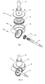
- Figure 1 shows, schematically, in perspective exploded, a reducer according to the invention.
- Figure 2 shows schematically, also in perspective, this same reducer, after assembly.
- Figure 3 shows, in a simplified way, a perspective rear side of a concrete mixer according to the invention, provided with a reducer also according to the invention, upon transmission of the rotational movement to the tank, and another reducer, also according to some of the characteristics of the invention, the transmission of the tilting movement to the arm tilting tank support, still allowing to identify areas corresponding to the amplifications represented in FIGS. 4 and 5.
- the perspective we took by frontal view the corresponding view to the placement of a worker facing the mouth of the tank.
- FIGS. 4 and 5 represent amplified perspective views, respectively, the area of the manual tilting handwheel of the tilting support arm of the tank and the area of the reducer and the motor for actuating the rotational movement of the tank around its axis.
- Figures 1 and 2 which represent a particular configuration of the gearbox (35) in question, it consists a body which, on one side, defines a motor connection flange (30) - visible in Figure 3 - and a seat for a bearing (34) for supporting the worm (38) which is the shaft (31) itself of the engine.
- the body (36) is open from the side the hollow toothed wheel (39), which is enveloped by this body but has no support point on this body, being fixed directly on the shaft (40) of the tank (4), this shaft being supported on the support (42) which serves simultaneously from cover to body.
- fixing the cover (42) to the body (36) is made by means of screws and the same happens to the fixing of the motor to said flange, which serves as a cover for the motor.
- the fixing of the motor (30) to the flange and the bearing (34) ensure the centering of the shaft / worm (31, 38), while centering the wheel hollow toothing is ensured by its placement in the tree (40).
- Figures 3 and 5 demonstrate the application of this reducer (35) on a concrete mixer (1).
- the reducer (35) is applied to the shaft (40) of the tank (4), being screwed to the support cube (42) of the shaft of the tank (4).
- This type of compact reducer applied to the concrete mixer, allows to eliminate, in an efficient and simple way, the classic transmission by pinion which has as disadvantages its operating noise and the danger of crushing, allowing easier certification of the product in the outline of community rules.
- This type of reducer can also be applied to tilting the tank (4), according to Figure 4, the arm shaft (3) being applied to the wheel hollow teeth and - in the case of manual actuation - the worm being linked to a steering wheel (or crank), either directly or, preferably, by means of a pair of bevel gears allowing the axis of rotation to be arranged of the steering wheel parallel to the tilting axis of said arm (3).
- This allows greater lightness during actuation, even in the case of actuation manual, as well as the elimination of the existing brake on concrete mixers traditional, thereby removing the risk associated with the incorrect manipulation of this.
Abstract
Description
- Bétonnière 1;
- Bâti 2;
- Bras basculant 3;
- Moteur 30;
- Arbre 31;
- Roulement 34 ;
- Réducteur 35;
- Corps 36;
- Vis sans fin 38;
- Roue à denture creuse 39;
- Cuve/organe extérieur à actionner 4;
- Arbre 40;
- Couvercle/support 42.
Claims (8)
- Réducteur de transmission mécanique (35) comprenant un corps (36), une vis sans fin (38) et une roue à denture creuse (39), caractérisé par ne posséder, lui-même, aucun arbre ou aucun roulement ou palier, l'arbre (31) de support de la vis sans fin étant l'arbre du moteur (30) et l'arbre de la roue à denture creuse (39) étant l'arbre (40) de l'organe extérieur à actionner (4).
- Réducteur selon la revendication antérieure, caractérisé en ce que la roue à denture creuse (39) n'est pas supportée sur le corps (36.
- Réducteur selon la revendication antérieure, caractérisé en ce que le corps (36) est ouvert du côté de la dite roue à denture creuse (39) et le support (42) de l'arbre (40) de l'organe extérieur à actionner (4) sert de couvercle au corps mentionné, en étanchant le réducteur.
- Réducteur selon la revendication 1, caractérisé en ce que le corps (36) n'est pourvu que d'un point d'appui pour un roulement (34) d'appui de l'arbre du moteur/vis sans fin (31, 38).
- Réducteur selon la revendication antérieure, caractérisé en ce que le corps est pourvu d'une bride de liaison au moteur (30), laquelle remplace le traditionnel couvercle du moteur.
- Bétonnière (1) caractérisée en ce qu'elle a un réducteur (35), selon quelqu'une des revendications antérieures, monté sur la partie centrale de son bras basculant (3) en forme de «U» et directement lié à l'arbre (40) de la cuve (4).
- Bétonnière selon la revendication antérieure, caractérisée en ce que le moteur (30) assume une position substantiellement parallèle à la partie centrale du bras (3) en forme de «U».
- Bétonnière selon quelqu'une des revendications 6 ou 7, caractérisée en ce que le mouvement basculant du bras (3) est actionné au moyen d'un réducteur de transmission mécanique de vis sans fin/roue à denture creuse, notamment selon quelqu'une des revendications 1 ou 2, et manuellement ou à moteur, en ce cas-ci possédant une bride de liaison au moteur et, en ce cas-la, étant actionné par un volant ou une manivelle lié au respectif arbre/vis sans fin, notamment au mayen d'un pair de pair de pignons coniques.
Applications Claiming Priority (2)
| Application Number | Priority Date | Filing Date | Title |
|---|---|---|---|
| PT10278002A PT102780B (pt) | 2002-05-20 | 2002-05-20 | Redutor de transmissao e sua aplicacao |
| PT10278002 | 2002-05-20 |
Publications (2)
| Publication Number | Publication Date |
|---|---|
| EP1365171A2 true EP1365171A2 (fr) | 2003-11-26 |
| EP1365171A3 EP1365171A3 (fr) | 2004-09-29 |
Family
ID=20086108
Family Applications (1)
| Application Number | Title | Priority Date | Filing Date |
|---|---|---|---|
| EP03011429A Withdrawn EP1365171A3 (fr) | 2002-05-20 | 2003-05-20 | Réducteur de transmission mécanique à vis sans fin pour bétonnière |
Country Status (2)
| Country | Link |
|---|---|
| EP (1) | EP1365171A3 (fr) |
| PT (1) | PT102780B (fr) |
Cited By (2)
| Publication number | Priority date | Publication date | Assignee | Title |
|---|---|---|---|---|
| CN104613130A (zh) * | 2015-01-28 | 2015-05-13 | 周正英 | 一种蜗轮蜗杆减速器 |
| CN106346612A (zh) * | 2016-09-07 | 2017-01-25 | 江苏大学 | 一种升降振动式水泥沙胶搅拌机构 |
Families Citing this family (1)
| Publication number | Priority date | Publication date | Assignee | Title |
|---|---|---|---|---|
| CN109159297A (zh) * | 2018-10-29 | 2019-01-08 | 长安大学 | 一种双蜗轮单蜗杆传动联体筒式立轴搅拌机 |
Citations (8)
| Publication number | Priority date | Publication date | Assignee | Title |
|---|---|---|---|---|
| GB127560A (en) * | 1918-05-29 | 1920-01-29 | Nathan Clarke Johnson | Improvements relating to the Mixing of Cement and Apparatus therefor. |
| DE871720C (de) * | 1950-11-13 | 1953-03-26 | Urpo Ristola | Mischer fuer Beton und aehnliche Baumaterialien |
| GB718945A (en) * | 1952-01-29 | 1954-11-24 | Bishop Arthur E | Improved concrete mixer |
| CH365320A (fr) * | 1959-03-26 | 1962-10-31 | Stothert & Pitt Ltd | Bétonnière |
| FR2748436A1 (fr) * | 1996-05-07 | 1997-11-14 | Valeo Systemes Dessuyage | Motoreducteur pour essuie-glace sans butee de blocage d'arbre |
| FR2752391A3 (fr) * | 1996-06-14 | 1998-02-20 | Imer Int Spa | Betonniere |
| US5836219A (en) * | 1995-08-25 | 1998-11-17 | Siemens Aktiengesellshcaft | Gear-case arrangement for a motor-gear drive unit, in particular for automobile window lifters or the like |
| FR2803557A3 (fr) * | 2000-01-11 | 2001-07-13 | Imer Internat Spa | Betonniere |
-
2002
- 2002-05-20 PT PT10278002A patent/PT102780B/pt not_active IP Right Cessation
-
2003
- 2003-05-20 EP EP03011429A patent/EP1365171A3/fr not_active Withdrawn
Patent Citations (8)
| Publication number | Priority date | Publication date | Assignee | Title |
|---|---|---|---|---|
| GB127560A (en) * | 1918-05-29 | 1920-01-29 | Nathan Clarke Johnson | Improvements relating to the Mixing of Cement and Apparatus therefor. |
| DE871720C (de) * | 1950-11-13 | 1953-03-26 | Urpo Ristola | Mischer fuer Beton und aehnliche Baumaterialien |
| GB718945A (en) * | 1952-01-29 | 1954-11-24 | Bishop Arthur E | Improved concrete mixer |
| CH365320A (fr) * | 1959-03-26 | 1962-10-31 | Stothert & Pitt Ltd | Bétonnière |
| US5836219A (en) * | 1995-08-25 | 1998-11-17 | Siemens Aktiengesellshcaft | Gear-case arrangement for a motor-gear drive unit, in particular for automobile window lifters or the like |
| FR2748436A1 (fr) * | 1996-05-07 | 1997-11-14 | Valeo Systemes Dessuyage | Motoreducteur pour essuie-glace sans butee de blocage d'arbre |
| FR2752391A3 (fr) * | 1996-06-14 | 1998-02-20 | Imer Int Spa | Betonniere |
| FR2803557A3 (fr) * | 2000-01-11 | 2001-07-13 | Imer Internat Spa | Betonniere |
Cited By (2)
| Publication number | Priority date | Publication date | Assignee | Title |
|---|---|---|---|---|
| CN104613130A (zh) * | 2015-01-28 | 2015-05-13 | 周正英 | 一种蜗轮蜗杆减速器 |
| CN106346612A (zh) * | 2016-09-07 | 2017-01-25 | 江苏大学 | 一种升降振动式水泥沙胶搅拌机构 |
Also Published As
| Publication number | Publication date |
|---|---|
| EP1365171A3 (fr) | 2004-09-29 |
| PT102780B (pt) | 2004-10-29 |
| PT102780A (pt) | 2003-01-31 |
Similar Documents
| Publication | Publication Date | Title |
|---|---|---|
| FR2492027A1 (fr) | Procede de montage d'un motoreducteur a vis sans fin et double chaine cinematique et motoreducteur correspondant | |
| EP1365171A2 (fr) | Réducteur de transmission mécanique à vis sans fin pour bétonnière | |
| EP0004230A1 (fr) | Dispositif de commande et de contrôle de l'inclinaison de la caisse d'un véhicule | |
| FR3042569A1 (fr) | Boite de vitesses pour equipement de motoculture et equipement de motoculture comprenant une telle boite de vitesses. | |
| EP0730991B2 (fr) | Dispositif de transmission | |
| FR2558233A1 (fr) | Ensemble d'essieux d'entrainement a plusieurs gammes pour un vehicule automobile | |
| FR2636894A1 (fr) | Ensemble de transformation d'un vehicule a deux roues motrices en vehicule a quatre roues motrices | |
| FR2892168A1 (fr) | Boite de vitesses pour equipement de motoculture | |
| FR2561341A1 (fr) | Reducteur de vitesse a composantes axiales et transversales equilibrees | |
| FR2726619A1 (fr) | Boite de vitesses du type a deux arbres secondaires | |
| EP1097317B1 (fr) | Transmission a inverseur montee entre une boite de vitesses et au moins deux roues motrices | |
| CH277293A (fr) | Mélangeur. | |
| FR2542806A1 (fr) | Dispositif d'entrainement de l'arbre a cames d'un moteur a combustion interne | |
| FR2754035A1 (fr) | Dispositif de transmission pour vehicule automobile | |
| FR2757239A1 (fr) | Systeme d'equilibrage d'un moteur a combustion interne | |
| FR2812843A1 (fr) | Unite d'entrainement de chariot transporteur | |
| FR2688556A1 (fr) | Systeme d'accouplement d'entrainement en rotation de l'organe rotatif d'un dispositif de travail a un vehicule porteur. | |
| FR2543641A1 (fr) | Reducteur de vitesse a engrenages, en particulier pour telepherique, ou analogue | |
| EP0001366A1 (fr) | Train avant simplifié à deux roues motrices pour véhicule automobile | |
| FR2711720A1 (fr) | Dispositif de renvoi d'angle pour volet roulant. | |
| FR2555274A1 (fr) | Joint de transmission a engrenages coniques | |
| FR2535577A1 (fr) | Dispositif d'entrainement d'un bras de petrin | |
| FR2624668A1 (fr) | Moteur electrique a transmission | |
| FR2791407A1 (fr) | Transmission pour vehicule automobile a boite de vitesses automatiques | |
| FR2674812A3 (fr) | Structure de mecanisme de transmission pour bicyclettes. |
Legal Events
| Date | Code | Title | Description |
|---|---|---|---|
| PUAI | Public reference made under article 153(3) epc to a published international application that has entered the european phase |
Free format text: ORIGINAL CODE: 0009012 |
|
| AK | Designated contracting states |
Kind code of ref document: A2 Designated state(s): AT BE BG CH CY CZ DE DK EE ES FI FR GB GR HU IE IT LI LU MC NL PT RO SE SI SK TR |
|
| AX | Request for extension of the european patent |
Extension state: AL LT LV MK |
|
| PUAL | Search report despatched |
Free format text: ORIGINAL CODE: 0009013 |
|
| AK | Designated contracting states |
Kind code of ref document: A3 Designated state(s): AT BE BG CH CY CZ DE DK EE ES FI FR GB GR HU IE IT LI LU MC NL PT RO SE SI SK TR |
|
| AX | Request for extension of the european patent |
Extension state: AL LT LV MK |
|
| RIC1 | Information provided on ipc code assigned before grant |
Ipc: 7B 28C 5/26 - Ipc: 7B 28C 5/08 B Ipc: 7F 16H 57/02 B Ipc: 7F 16H 1/16 A |
|
| 17P | Request for examination filed |
Effective date: 20050328 |
|
| AKX | Designation fees paid |
Designated state(s): AT BE BG CH CY CZ DE DK EE ES FI FR GB GR HU IE IT LI LU MC NL PT RO SE SI SK TR |
|
| 17Q | First examination report despatched |
Effective date: 20050623 |
|
| STAA | Information on the status of an ep patent application or granted ep patent |
Free format text: STATUS: THE APPLICATION IS DEEMED TO BE WITHDRAWN |
|
| 18D | Application deemed to be withdrawn |
Effective date: 20060708 |