EP1364576A2 - Stall mit Bodenmatte - Google Patents
Stall mit Bodenmatte Download PDFInfo
- Publication number
- EP1364576A2 EP1364576A2 EP03076571A EP03076571A EP1364576A2 EP 1364576 A2 EP1364576 A2 EP 1364576A2 EP 03076571 A EP03076571 A EP 03076571A EP 03076571 A EP03076571 A EP 03076571A EP 1364576 A2 EP1364576 A2 EP 1364576A2
- Authority
- EP
- European Patent Office
- Prior art keywords
- mat
- concrete
- stable
- floor
- grid
- Prior art date
- Legal status (The legal status is an assumption and is not a legal conclusion. Google has not performed a legal analysis and makes no representation as to the accuracy of the status listed.)
- Withdrawn
Links
Images


Classifications
-
- A—HUMAN NECESSITIES
- A01—AGRICULTURE; FORESTRY; ANIMAL HUSBANDRY; HUNTING; TRAPPING; FISHING
- A01K—ANIMAL HUSBANDRY; AVICULTURE; APICULTURE; PISCICULTURE; FISHING; REARING OR BREEDING ANIMALS, NOT OTHERWISE PROVIDED FOR; NEW BREEDS OF ANIMALS
- A01K1/00—Housing animals; Equipment therefor
- A01K1/015—Floor coverings, e.g. bedding-down sheets ; Stable floors
- A01K1/0157—Mats; Sheets
Definitions
- the present invention relates to a stable for livestock, comprising a building with a floor of concrete and a mat of resilient material, such as plastic and/or rubber, on the concrete floor.
- the mat is thus intended to simulate to some extent the situation outside in the meadow, as far as this is possible.
- the welfare of the livestock is important from a social viewpoint and it has further been found that the production of the livestock, measured for instance in quantities of milk, is higher when the livestock feel more comfortable.
- the mat is fixed, since if it could shift the animals of the livestock could fall as a result of walking on the mat when it shifts.
- a first solution here for from the known art is that the mats are made so thick that they remain in place because of their own weight.
- An obvious drawback here are the associated costs. In order to fix the mat through its own weight much more material is used for the mat than is necessary to achieve the desired effect of simulating a meadow.
- the present invention has for its object to obviate or at least considerably diminish the problems of the known art, for which purpose the mat is arranged on the stable floor and fixed against shifting by at least one element for fastening to the stable floor and for connecting to or connected to the mat.
- Such an element according to the present invention then forms an intermediary between the concrete floor and the mat in order to fix the mat onto the concrete floor.
- the mat can have the thickness required for the desired effect and does not have to be made thicker.
- the costs are hereby also considerably limited compared to the solutions known in the art. It is moreover ensured that the mat is then fixed onto the concrete floor.
- the concrete floor itself forms an anchoring for the mat in that the concrete of the concrete floor engages the element and an effective fixing is established by the connection of the element to the mat.
- the element can herein take the form of a grid.
- An effective design is hereby realized to provide a high degree of engagement on the element by the poured concrete of the concrete floor, while a large area of the element, which lies freely on the surface of the concrete floor, is simultaneously available for fixing of the mat.
- the very high degree of engagement is particularly favourable if the mats are placed or used at a location in the stable where a device, such as a per se known manure scraper, is also being used for cleaning purposes.
- a connection between mat and floor via the element which provides insufficient fixation for instance if the mat can be released from the floor by manual force, cannot withstand the forces exerted on the mat by such a device, and so the mat can be simply pulled loose by this device.
- a grid-like or otherwise designed element can be pressed into not yet hardened concrete during the construction of the stable or at a remote location (prefabrication).
- An effective and efficient anchoring of the element in the concrete floor is hereby ensured, as well as fixing of the mat thereon.
- the mat can then be arranged on the element at a later stage when the concrete has actually hardened, or in advance, i.e. before pouring of the concrete, or the mat and the element can form a unit.
- the element can preferably be connected to the mat.
- An example hereof is vulcanization of the element and the material of the mat. Due to the properties of the element functioning as intermediary a reliable connection between the concrete floor and the mat can thus be realized, which means a considerable improvement compared to the known art.
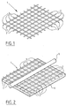
- Fig. 1 shows a grid-like element 1, which can be used to form an intermediary component between a concrete stable floor and a mat thereon.
- the grid-like element 1 comprises a number of wires 2 located on the bottom in fig. 1 and also a number of wires 3 arranged on top of and fixedly connected to wires 2.
- the grid-like element 1 being a specific embodiment of the invention given by way of example, can be pressed into a not yet hardened layer of concrete 4.
- the bottom wires 2 herein sink into the not yet hardened layer of concrete 4, which is brought about with a roller 5 or a press, this latter option not being shown.
- the wires 3 (on top of wires 2) herein remain visible and accessible in or above the surface of the layer of concrete 4 still to harden and for contact.
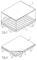
- a mat 7 can be placed on the hardened layer of concrete 6 and fastened to the upper wires 3 of grid-like element 1, wherein the wires 2 located under the surface of the hardened concrete 6 ensure a fixing of element 1 and the wires 3 located on top of grid-like element 1 lie exposed in the upper surface of the hardened concrete 6 for placing into contact with mat 7.
- the latter can take place by vulcanization, adhesion or in other manner with means which are readily suitable to fixedly connect the top wires 3 of grid-like element 1 to mat 7, where this would be considerably less readily possible without interposing of the grid-like element 1 functioning as intermediary.
- grid-like element 1 is first pressed into not yet hardened concrete and mat 7 is arranged thereon later.
- the mat 7 is provided beforehand with a grid-like element 1 by mutual connection thereto or to a similar configuration forming an intermediary. This is even recommended to some extent, since prefabricated elements can hereby be produced.
- the mat can be placed with this construction on the top side thereof in a holder or the like and concrete is then poured thereover.
- the holder which is used here has dimensions such that prefabricated elements are manufactured with standard dimensions, which can facilitate placing at the intended location in the stable, to the extent that standard dimensions are also used in this stable.
- Fig. 5 shows an alternative embodiment to that of figures 1-4.
- Mat 7 herein forms a unit with a grid-like element 8.
- Grid-like element 8 comprises protrusions 9 on the side of mat 7 which is directed toward a layer of concrete 6 which has not yet hardened.
- Mat 7 is lowered along arrows A and B, in that order, and pressed into the not yet hardened concrete 6 so that air between mat 7 and concrete 6 has the opportunity to escape.
- Protrusions 9 are hereby pressed very deeply into concrete 6 and as little air as possible remains between mat 7 and concrete 6, which air could prevent a good adhesion.
- Protrusions 9 are placed in rows with channels 10 therebetween. Arranged between the protrusions 9 in a row as shown in fig. 6B are shoulders 11 which are wider than the protrusions 9 in the longitudinal direction of a row with protrusions 9, but wherein the shoulders 11 are formed lower than protrusions 9. This is shown in a perspective view in fig. 7.
- protrusions 12 have a narrowed portion followed by a widened portion in a direction away from mat 7.
- the adhesion of the not yet hardened concrete to the protrusions 12 can hereby be further optimized compared to the protrusions 9 extending straight upward from mat 7.
- Such an embodiment is particularly favourable because the mat and the element form a unit and element 8 is formed by protrusions 9, 11 and/or 12, whereby a very durable fixation can be realized which is not easy to break, not even if a manure scraper is drawn over mat 7 (over the upper surface thereof, in the situation assembled with a concrete plate 6).
- the element which is described in the foregoing as a grid-like element does not have to be a grid-like element which is sunk into the not yet hardened concrete of the stable floor, but that it is equally possible to provide an existing stable floor, which has therefore already hardened, with a mat in the manner set forth according to the invention, by arranging anchors in the hardened concrete for fixing the mat to be positioned thereover. It is important for the present invention that between the hardened concrete floor and the mat there is arranged an intermediary (which can form an integral part of the mat), for instance in the form of a grid-like element and for instance in newly poured concrete, as described and shown here, but alternatively in other manner, in order to fix the mat relative to the concrete floor in the finally fitted situation.
- an intermediary which can form an integral part of the mat
Landscapes
- Life Sciences & Earth Sciences (AREA)
- Environmental Sciences (AREA)
- Zoology (AREA)
- Animal Husbandry (AREA)
- Biodiversity & Conservation Biology (AREA)
- Floor Finish (AREA)
- Housing For Livestock And Birds (AREA)
Applications Claiming Priority (2)
| Application Number | Priority Date | Filing Date | Title |
|---|---|---|---|
| NL1020660 | 2002-05-23 | ||
| NL1020660A NL1020660C2 (nl) | 2002-05-23 | 2002-05-23 | Stal met mat op vloer. |
Publications (2)
| Publication Number | Publication Date |
|---|---|
| EP1364576A2 true EP1364576A2 (de) | 2003-11-26 |
| EP1364576A3 EP1364576A3 (de) | 2004-01-07 |
Family
ID=29398576
Family Applications (1)
| Application Number | Title | Priority Date | Filing Date |
|---|---|---|---|
| EP03076571A Withdrawn EP1364576A3 (de) | 2002-05-23 | 2003-05-23 | Stall mit Bodenmatte |
Country Status (2)
| Country | Link |
|---|---|
| EP (1) | EP1364576A3 (de) |
| NL (1) | NL1020660C2 (de) |
Cited By (1)
| Publication number | Priority date | Publication date | Assignee | Title |
|---|---|---|---|---|
| EP1747716A1 (de) * | 2005-07-25 | 2007-01-31 | Hartmann Grundbesitz GmbH & Co. KG | Betonfertigteilesystem für einen Stallboden, Verfahren zur Herstellung eines Stallbodens, Stallboden und ein den Stallboden umfassender Stall |
Family Cites Families (5)
| Publication number | Priority date | Publication date | Assignee | Title |
|---|---|---|---|---|
| GB543829A (en) * | 1941-05-30 | 1942-03-13 | Cornelis Waltherus Bastiaansen | Improvements in and relating to floors for stables and the like |
| GB1458257A (en) * | 1974-03-07 | 1976-12-15 | Westhoff H | Floor or prefabricated floor element |
| DE2649054A1 (de) * | 1976-10-28 | 1978-05-03 | Freudenberg Carl Fa | Tierboxeneinlage |
| DE3320346C2 (de) * | 1983-06-04 | 1985-04-11 | Dynamit Nobel Ag, 5210 Troisdorf | Kernschicht für eine Aufsprungmatte |
| WO2000016611A2 (en) * | 1998-09-18 | 2000-03-30 | Patrick Roy Mooney | Apparatus for joining animal mats and covering slatted floors |
-
2002
- 2002-05-23 NL NL1020660A patent/NL1020660C2/nl not_active IP Right Cessation
-
2003
- 2003-05-23 EP EP03076571A patent/EP1364576A3/de not_active Withdrawn
Cited By (1)
| Publication number | Priority date | Publication date | Assignee | Title |
|---|---|---|---|---|
| EP1747716A1 (de) * | 2005-07-25 | 2007-01-31 | Hartmann Grundbesitz GmbH & Co. KG | Betonfertigteilesystem für einen Stallboden, Verfahren zur Herstellung eines Stallbodens, Stallboden und ein den Stallboden umfassender Stall |
Also Published As
| Publication number | Publication date |
|---|---|
| EP1364576A3 (de) | 2004-01-07 |
| NL1020660C2 (nl) | 2003-11-25 |
Similar Documents
| Publication | Publication Date | Title |
|---|---|---|
| US8668977B2 (en) | Support structures and methods | |
| JP5698304B2 (ja) | コンクリート構造物の製造方法 | |
| RU95113120A (ru) | Рельсовое крепление и способ его образования | |
| JP4541592B2 (ja) | 段差スラブ成形用コンクリート版及びこれを用いた段差スラブ構造 | |
| EP3162196B1 (de) | Gerilltes bodenelement für einen kuhstall, substrat und biegsame matte | |
| JP3721448B2 (ja) | 防蟻用断熱板の施工方法 | |
| KR101419449B1 (ko) | 트렌치 누수방지용 보강재 및 그 시공방법 | |
| KR20150145681A (ko) | 멀티기능을 가진 보도블록 | |
| JP2015208862A (ja) | ハーフプレキャスト版製造方法及びハーフプレキャスト版 | |
| KR20190011442A (ko) | 조립식 스포츠 코트 블럭 | |
| JP2010159586A (ja) | 土間廻り部の構造及びその施工方法 | |
| US4213210A (en) | Air channel device | |
| NL1020660C2 (nl) | Stal met mat op vloer. | |
| US20030192484A1 (en) | Cattle flooring method & apparatus | |
| JP3836016B2 (ja) | 埋込材ユニットおよびこれを使用したプレキャストコンクリート板ならびに中空スラブの構築方法 | |
| KR102175546B1 (ko) | 하프피씨 바닥판 및, 바닥판구조체 | |
| JP3241680B2 (ja) | 法面保護用コンクリートブロック集合体 | |
| KR102961532B1 (ko) | 층간소음저감바닥시공을 위한 시공재어셈블리 | |
| JP5547829B1 (ja) | 覆工材 | |
| JP3050701U (ja) | 連結敷設用床材 | |
| JP3488434B2 (ja) | 硬質タイルの敷設工法 | |
| JPH078562Y2 (ja) | 透水性タイルブロック | |
| JP2004293175A (ja) | 緑化路面用ベースプレート及びこれを用いた緑化路面形成方法 | |
| JP2003064684A (ja) | 緑化工法 | |
| JP2551992Y2 (ja) | タイル取付構造 |
Legal Events
| Date | Code | Title | Description |
|---|---|---|---|
| PUAI | Public reference made under article 153(3) epc to a published international application that has entered the european phase |
Free format text: ORIGINAL CODE: 0009012 |
|
| PUAL | Search report despatched |
Free format text: ORIGINAL CODE: 0009013 |
|
| AK | Designated contracting states |
Kind code of ref document: A2 Designated state(s): AT BE BG CH CY CZ DE DK EE ES FI FR GB GR HU IE IT LI LU MC NL PT RO SE SI SK TR |
|
| AX | Request for extension of the european patent |
Extension state: AL LT LV MK |
|
| AK | Designated contracting states |
Kind code of ref document: A3 Designated state(s): AT BE BG CH CY CZ DE DK EE ES FI FR GB GR HU IE IT LI LU MC NL PT RO SE SI SK TR |
|
| AX | Request for extension of the european patent |
Extension state: AL LT LV MK |
|
| AKX | Designation fees paid | ||
| REG | Reference to a national code |
Ref country code: DE Ref legal event code: 8566 |
|
| STAA | Information on the status of an ep patent application or granted ep patent |
Free format text: STATUS: THE APPLICATION IS DEEMED TO BE WITHDRAWN |
|
| 18D | Application deemed to be withdrawn |
Effective date: 20040708 |