EP1363142A1 - Revetement reduisant la reflexion, materiau de base et transducteur photoelectrique pourvu de ce revetement reducteur de reflexion - Google Patents
Revetement reduisant la reflexion, materiau de base et transducteur photoelectrique pourvu de ce revetement reducteur de reflexion Download PDFInfo
- Publication number
- EP1363142A1 EP1363142A1 EP01271550A EP01271550A EP1363142A1 EP 1363142 A1 EP1363142 A1 EP 1363142A1 EP 01271550 A EP01271550 A EP 01271550A EP 01271550 A EP01271550 A EP 01271550A EP 1363142 A1 EP1363142 A1 EP 1363142A1
- Authority
- EP
- European Patent Office
- Prior art keywords
- antireflection film
- binder layer
- fine particles
- substrate
- photoelectric conversion
- Prior art date
- Legal status (The legal status is an assumption and is not a legal conclusion. Google has not performed a legal analysis and makes no representation as to the accuracy of the status listed.)
- Withdrawn
Links
- 239000011248 coating agent Substances 0.000 title abstract description 32
- 238000000576 coating method Methods 0.000 title abstract description 32
- 239000000463 material Substances 0.000 title description 12
- 239000011230 binding agent Substances 0.000 claims abstract description 65
- 239000010419 fine particle Substances 0.000 claims description 63
- 239000000758 substrate Substances 0.000 claims description 38
- VYPSYNLAJGMNEJ-UHFFFAOYSA-N Silicium dioxide Chemical compound O=[Si]=O VYPSYNLAJGMNEJ-UHFFFAOYSA-N 0.000 claims description 29
- 238000006243 chemical reaction Methods 0.000 claims description 27
- 238000005299 abrasion Methods 0.000 claims description 25
- 239000002245 particle Substances 0.000 claims description 24
- 238000012360 testing method Methods 0.000 claims description 21
- 239000011521 glass Substances 0.000 claims description 17
- GWEVSGVZZGPLCZ-UHFFFAOYSA-N Titan oxide Chemical compound O=[Ti]=O GWEVSGVZZGPLCZ-UHFFFAOYSA-N 0.000 claims description 2
- TWNQGVIAIRXVLR-UHFFFAOYSA-N oxo(oxoalumanyloxy)alumane Chemical compound O=[Al]O[Al]=O TWNQGVIAIRXVLR-UHFFFAOYSA-N 0.000 claims description 2
- BPUBBGLMJRNUCC-UHFFFAOYSA-N oxygen(2-);tantalum(5+) Chemical compound [O-2].[O-2].[O-2].[O-2].[O-2].[Ta+5].[Ta+5] BPUBBGLMJRNUCC-UHFFFAOYSA-N 0.000 claims description 2
- RVTZCBVAJQQJTK-UHFFFAOYSA-N oxygen(2-);zirconium(4+) Chemical compound [O-2].[O-2].[Zr+4] RVTZCBVAJQQJTK-UHFFFAOYSA-N 0.000 claims description 2
- 229910052814 silicon oxide Inorganic materials 0.000 claims description 2
- 229910001936 tantalum oxide Inorganic materials 0.000 claims description 2
- OGIDPMRJRNCKJF-UHFFFAOYSA-N titanium oxide Inorganic materials [Ti]=O OGIDPMRJRNCKJF-UHFFFAOYSA-N 0.000 claims description 2
- 229910001928 zirconium oxide Inorganic materials 0.000 claims description 2
- 239000010408 film Substances 0.000 description 114
- 150000002736 metal compounds Chemical class 0.000 description 21
- 238000000034 method Methods 0.000 description 19
- 230000000052 comparative effect Effects 0.000 description 16
- VEXZGXHMUGYJMC-UHFFFAOYSA-N Hydrochloric acid Chemical compound Cl VEXZGXHMUGYJMC-UHFFFAOYSA-N 0.000 description 14
- 238000005259 measurement Methods 0.000 description 12
- 230000007062 hydrolysis Effects 0.000 description 11
- 238000006460 hydrolysis reaction Methods 0.000 description 11
- 229910044991 metal oxide Inorganic materials 0.000 description 11
- 150000004706 metal oxides Chemical class 0.000 description 11
- 239000011148 porous material Substances 0.000 description 11
- XLYOFNOQVPJJNP-UHFFFAOYSA-N water Substances O XLYOFNOQVPJJNP-UHFFFAOYSA-N 0.000 description 11
- 239000010409 thin film Substances 0.000 description 10
- 238000010438 heat treatment Methods 0.000 description 9
- 230000000694 effects Effects 0.000 description 8
- 239000000203 mixture Substances 0.000 description 8
- 239000003513 alkali Substances 0.000 description 7
- 239000003054 catalyst Substances 0.000 description 7
- 230000003287 optical effect Effects 0.000 description 7
- DNIAPMSPPWPWGF-UHFFFAOYSA-N Propylene glycol Chemical compound CC(O)CO DNIAPMSPPWPWGF-UHFFFAOYSA-N 0.000 description 6
- 239000006185 dispersion Substances 0.000 description 6
- ZNQVEEAIQZEUHB-UHFFFAOYSA-N 2-ethoxyethanol Chemical compound CCOCCO ZNQVEEAIQZEUHB-UHFFFAOYSA-N 0.000 description 5
- 150000004703 alkoxides Chemical class 0.000 description 5
- 229910052751 metal Inorganic materials 0.000 description 5
- 229910052710 silicon Inorganic materials 0.000 description 5
- 239000010703 silicon Substances 0.000 description 5
- 239000002904 solvent Substances 0.000 description 5
- SVTBMSDMJJWYQN-UHFFFAOYSA-N 2-methylpentane-2,4-diol Chemical compound CC(O)CC(C)(C)O SVTBMSDMJJWYQN-UHFFFAOYSA-N 0.000 description 4
- 230000008859 change Effects 0.000 description 4
- SWXVUIWOUIDPGS-UHFFFAOYSA-N diacetone alcohol Chemical compound CC(=O)CC(C)(C)O SWXVUIWOUIDPGS-UHFFFAOYSA-N 0.000 description 4
- 239000002184 metal Substances 0.000 description 4
- 239000011164 primary particle Substances 0.000 description 4
- -1 silicon alkoxide Chemical class 0.000 description 4
- 239000000126 substance Substances 0.000 description 4
- QTBSBXVTEAMEQO-UHFFFAOYSA-N Acetic acid Chemical compound CC(O)=O QTBSBXVTEAMEQO-UHFFFAOYSA-N 0.000 description 3
- LFQSCWFLJHTTHZ-UHFFFAOYSA-N Ethanol Chemical compound CCO LFQSCWFLJHTTHZ-UHFFFAOYSA-N 0.000 description 3
- LYCAIKOWRPUZTN-UHFFFAOYSA-N Ethylene glycol Chemical compound OCCO LYCAIKOWRPUZTN-UHFFFAOYSA-N 0.000 description 3
- OKKJLVBELUTLKV-UHFFFAOYSA-N Methanol Chemical compound OC OKKJLVBELUTLKV-UHFFFAOYSA-N 0.000 description 3
- HEMHJVSKTPXQMS-UHFFFAOYSA-M Sodium hydroxide Chemical compound [OH-].[Na+] HEMHJVSKTPXQMS-UHFFFAOYSA-M 0.000 description 3
- 239000003377 acid catalyst Substances 0.000 description 3
- 125000000217 alkyl group Chemical group 0.000 description 3
- 229910021417 amorphous silicon Inorganic materials 0.000 description 3
- 230000015572 biosynthetic process Effects 0.000 description 3
- 239000000919 ceramic Substances 0.000 description 3
- 238000004140 cleaning Methods 0.000 description 3
- 238000006482 condensation reaction Methods 0.000 description 3
- 230000003301 hydrolyzing effect Effects 0.000 description 3
- VLKZOEOYAKHREP-UHFFFAOYSA-N n-Hexane Chemical compound CCCCCC VLKZOEOYAKHREP-UHFFFAOYSA-N 0.000 description 3
- 239000000377 silicon dioxide Substances 0.000 description 3
- 239000007787 solid Substances 0.000 description 3
- 238000003756 stirring Methods 0.000 description 3
- CSCPPACGZOOCGX-UHFFFAOYSA-N Acetone Chemical compound CC(C)=O CSCPPACGZOOCGX-UHFFFAOYSA-N 0.000 description 2
- QGZKDVFQNNGYKY-UHFFFAOYSA-N Ammonia Chemical compound N QGZKDVFQNNGYKY-UHFFFAOYSA-N 0.000 description 2
- LRHPLDYGYMQRHN-UHFFFAOYSA-N N-Butanol Chemical compound CCCCO LRHPLDYGYMQRHN-UHFFFAOYSA-N 0.000 description 2
- XUIMIQQOPSSXEZ-UHFFFAOYSA-N Silicon Chemical compound [Si] XUIMIQQOPSSXEZ-UHFFFAOYSA-N 0.000 description 2
- 239000002253 acid Substances 0.000 description 2
- 125000004429 atom Chemical group 0.000 description 2
- 239000007795 chemical reaction product Substances 0.000 description 2
- 238000005229 chemical vapour deposition Methods 0.000 description 2
- 150000001875 compounds Chemical class 0.000 description 2
- 239000006059 cover glass Substances 0.000 description 2
- 239000013078 crystal Substances 0.000 description 2
- 238000007647 flexography Methods 0.000 description 2
- 229940051250 hexylene glycol Drugs 0.000 description 2
- 238000004519 manufacturing process Methods 0.000 description 2
- 125000000962 organic group Chemical group 0.000 description 2
- 239000000843 powder Substances 0.000 description 2
- POAOYUHQDCAZBD-UHFFFAOYSA-N 2-butoxyethanol Chemical compound CCCCOCCO POAOYUHQDCAZBD-UHFFFAOYSA-N 0.000 description 1
- YEYKMVJDLWJFOA-UHFFFAOYSA-N 2-propoxyethanol Chemical compound CCCOCCO YEYKMVJDLWJFOA-UHFFFAOYSA-N 0.000 description 1
- GRYLNZFGIOXLOG-UHFFFAOYSA-N Nitric acid Chemical compound O[N+]([O-])=O GRYLNZFGIOXLOG-UHFFFAOYSA-N 0.000 description 1
- CBENFWSGALASAD-UHFFFAOYSA-N Ozone Chemical compound [O-][O+]=O CBENFWSGALASAD-UHFFFAOYSA-N 0.000 description 1
- 239000004115 Sodium Silicate Substances 0.000 description 1
- 238000003854 Surface Print Methods 0.000 description 1
- RTAQQCXQSZGOHL-UHFFFAOYSA-N Titanium Chemical compound [Ti] RTAQQCXQSZGOHL-UHFFFAOYSA-N 0.000 description 1
- QCWXUUIWCKQGHC-UHFFFAOYSA-N Zirconium Chemical compound [Zr] QCWXUUIWCKQGHC-UHFFFAOYSA-N 0.000 description 1
- 239000003082 abrasive agent Substances 0.000 description 1
- 230000009471 action Effects 0.000 description 1
- 125000004423 acyloxy group Chemical group 0.000 description 1
- 239000000853 adhesive Substances 0.000 description 1
- 230000001070 adhesive effect Effects 0.000 description 1
- 150000001298 alcohols Chemical class 0.000 description 1
- 229910052782 aluminium Inorganic materials 0.000 description 1
- XAGFODPZIPBFFR-UHFFFAOYSA-N aluminium Chemical compound [Al] XAGFODPZIPBFFR-UHFFFAOYSA-N 0.000 description 1
- 125000002344 aminooxy group Chemical group [H]N([H])O[*] 0.000 description 1
- 229910021529 ammonia Inorganic materials 0.000 description 1
- 239000003125 aqueous solvent Substances 0.000 description 1
- 238000000149 argon plasma sintering Methods 0.000 description 1
- 239000013590 bulk material Substances 0.000 description 1
- 125000001309 chloro group Chemical group Cl* 0.000 description 1
- 239000008119 colloidal silica Substances 0.000 description 1
- 238000011109 contamination Methods 0.000 description 1
- 229910021419 crystalline silicon Inorganic materials 0.000 description 1
- 230000018044 dehydration Effects 0.000 description 1
- 238000006297 dehydration reaction Methods 0.000 description 1
- 238000003618 dip coating Methods 0.000 description 1
- 230000002708 enhancing effect Effects 0.000 description 1
- 239000004744 fabric Substances 0.000 description 1
- 239000005329 float glass Substances 0.000 description 1
- 229910021485 fumed silica Inorganic materials 0.000 description 1
- 230000004313 glare Effects 0.000 description 1
- 150000002334 glycols Chemical class 0.000 description 1
- 238000007646 gravure printing Methods 0.000 description 1
- 238000000227 grinding Methods 0.000 description 1
- 239000000413 hydrolysate Substances 0.000 description 1
- 238000007654 immersion Methods 0.000 description 1
- 230000006872 improvement Effects 0.000 description 1
- 229910052500 inorganic mineral Inorganic materials 0.000 description 1
- IQPQWNKOIGAROB-UHFFFAOYSA-N isocyanate group Chemical group [N-]=C=O IQPQWNKOIGAROB-UHFFFAOYSA-N 0.000 description 1
- 229910001635 magnesium fluoride Inorganic materials 0.000 description 1
- 238000000691 measurement method Methods 0.000 description 1
- 229910001507 metal halide Inorganic materials 0.000 description 1
- 150000005309 metal halides Chemical class 0.000 description 1
- 239000011707 mineral Substances 0.000 description 1
- 238000002156 mixing Methods 0.000 description 1
- 229910017604 nitric acid Inorganic materials 0.000 description 1
- 239000003960 organic solvent Substances 0.000 description 1
- 238000001020 plasma etching Methods 0.000 description 1
- 238000009832 plasma treatment Methods 0.000 description 1
- 239000004033 plastic Substances 0.000 description 1
- 229920003023 plastic Polymers 0.000 description 1
- 238000010248 power generation Methods 0.000 description 1
- 238000007639 printing Methods 0.000 description 1
- 239000000047 product Substances 0.000 description 1
- 230000001737 promoting effect Effects 0.000 description 1
- BDERNNFJNOPAEC-UHFFFAOYSA-N propan-1-ol Chemical compound CCCO BDERNNFJNOPAEC-UHFFFAOYSA-N 0.000 description 1
- 230000009467 reduction Effects 0.000 description 1
- 238000002407 reforming Methods 0.000 description 1
- 239000011347 resin Substances 0.000 description 1
- 229920005989 resin Polymers 0.000 description 1
- 238000005488 sandblasting Methods 0.000 description 1
- 238000007650 screen-printing Methods 0.000 description 1
- 239000011163 secondary particle Substances 0.000 description 1
- 125000005372 silanol group Chemical group 0.000 description 1
- 235000012239 silicon dioxide Nutrition 0.000 description 1
- 239000005361 soda-lime glass Substances 0.000 description 1
- NTHWMYGWWRZVTN-UHFFFAOYSA-N sodium silicate Chemical compound [Na+].[Na+].[O-][Si]([O-])=O NTHWMYGWWRZVTN-UHFFFAOYSA-N 0.000 description 1
- 229910052911 sodium silicate Inorganic materials 0.000 description 1
- 238000003980 solgel method Methods 0.000 description 1
- 238000001228 spectrum Methods 0.000 description 1
- 239000007921 spray Substances 0.000 description 1
- 238000005507 spraying Methods 0.000 description 1
- 229910052715 tantalum Inorganic materials 0.000 description 1
- GUVRBAGPIYLISA-UHFFFAOYSA-N tantalum atom Chemical compound [Ta] GUVRBAGPIYLISA-UHFFFAOYSA-N 0.000 description 1
- 229910052719 titanium Inorganic materials 0.000 description 1
- 239000010936 titanium Substances 0.000 description 1
- 238000002834 transmittance Methods 0.000 description 1
- 238000004506 ultrasonic cleaning Methods 0.000 description 1
- 239000012808 vapor phase Substances 0.000 description 1
- 229910052726 zirconium Inorganic materials 0.000 description 1
Images


Classifications
-
- H—ELECTRICITY
- H01—ELECTRIC ELEMENTS
- H01L—SEMICONDUCTOR DEVICES NOT COVERED BY CLASS H10
- H01L31/00—Semiconductor devices sensitive to infrared radiation, light, electromagnetic radiation of shorter wavelength or corpuscular radiation and specially adapted either for the conversion of the energy of such radiation into electrical energy or for the control of electrical energy by such radiation; Processes or apparatus specially adapted for the manufacture or treatment thereof or of parts thereof; Details thereof
- H01L31/02—Details
- H01L31/0216—Coatings
- H01L31/02161—Coatings for devices characterised by at least one potential jump barrier or surface barrier
- H01L31/02167—Coatings for devices characterised by at least one potential jump barrier or surface barrier for solar cells
- H01L31/02168—Coatings for devices characterised by at least one potential jump barrier or surface barrier for solar cells the coatings being antireflective or having enhancing optical properties for the solar cells
-
- G02B1/105—
-
- G—PHYSICS
- G02—OPTICS
- G02B—OPTICAL ELEMENTS, SYSTEMS OR APPARATUS
- G02B1/00—Optical elements characterised by the material of which they are made; Optical coatings for optical elements
- G02B1/10—Optical coatings produced by application to, or surface treatment of, optical elements
- G02B1/11—Anti-reflection coatings
-
- G—PHYSICS
- G02—OPTICS
- G02B—OPTICAL ELEMENTS, SYSTEMS OR APPARATUS
- G02B1/00—Optical elements characterised by the material of which they are made; Optical coatings for optical elements
- G02B1/10—Optical coatings produced by application to, or surface treatment of, optical elements
- G02B1/14—Protective coatings, e.g. hard coatings
-
- H—ELECTRICITY
- H01—ELECTRIC ELEMENTS
- H01J—ELECTRIC DISCHARGE TUBES OR DISCHARGE LAMPS
- H01J29/00—Details of cathode-ray tubes or of electron-beam tubes of the types covered by group H01J31/00
- H01J29/86—Vessels; Containers; Vacuum locks
- H01J29/89—Optical or photographic arrangements structurally combined or co-operating with the vessel
- H01J29/896—Anti-reflection means, e.g. eliminating glare due to ambient light
-
- H—ELECTRICITY
- H01—ELECTRIC ELEMENTS
- H01J—ELECTRIC DISCHARGE TUBES OR DISCHARGE LAMPS
- H01J2229/00—Details of cathode ray tubes or electron beam tubes
- H01J2229/89—Optical components associated with the vessel
- H01J2229/8913—Anti-reflection, anti-glare, viewing angle and contrast improving treatments or devices
-
- H—ELECTRICITY
- H01—ELECTRIC ELEMENTS
- H01J—ELECTRIC DISCHARGE TUBES OR DISCHARGE LAMPS
- H01J2229/00—Details of cathode ray tubes or electron beam tubes
- H01J2229/89—Optical components associated with the vessel
- H01J2229/8924—Optical components associated with the vessel having particular properties for protecting the vessel, e.g. against abrasion, water or shock
-
- Y—GENERAL TAGGING OF NEW TECHNOLOGICAL DEVELOPMENTS; GENERAL TAGGING OF CROSS-SECTIONAL TECHNOLOGIES SPANNING OVER SEVERAL SECTIONS OF THE IPC; TECHNICAL SUBJECTS COVERED BY FORMER USPC CROSS-REFERENCE ART COLLECTIONS [XRACs] AND DIGESTS
- Y02—TECHNOLOGIES OR APPLICATIONS FOR MITIGATION OR ADAPTATION AGAINST CLIMATE CHANGE
- Y02E—REDUCTION OF GREENHOUSE GAS [GHG] EMISSIONS, RELATED TO ENERGY GENERATION, TRANSMISSION OR DISTRIBUTION
- Y02E10/00—Energy generation through renewable energy sources
- Y02E10/50—Photovoltaic [PV] energy
-
- Y—GENERAL TAGGING OF NEW TECHNOLOGICAL DEVELOPMENTS; GENERAL TAGGING OF CROSS-SECTIONAL TECHNOLOGIES SPANNING OVER SEVERAL SECTIONS OF THE IPC; TECHNICAL SUBJECTS COVERED BY FORMER USPC CROSS-REFERENCE ART COLLECTIONS [XRACs] AND DIGESTS
- Y10—TECHNICAL SUBJECTS COVERED BY FORMER USPC
- Y10T—TECHNICAL SUBJECTS COVERED BY FORMER US CLASSIFICATION
- Y10T428/00—Stock material or miscellaneous articles
- Y10T428/25—Web or sheet containing structurally defined element or component and including a second component containing structurally defined particles
- Y10T428/259—Silicic material
Definitions
- the present invention relates to an antireflection film used for a vehicular glass, a showroom window, eyeglasses, an optical member such as a camera lens, or an information display such as a cathode ray tube. Further, the present invention relates to a substrate of glass, ceramic or the like having this antireflection film, and a photoelectric conversion device using them, for example, a solar cell panel.
- a substrate of glass, ceramic or the like sometimes has a surface on which an antireflection film is formed so as to transmit more light or prevent glare caused by reflection.
- an antireflection film a film that utilizes the difference in a refractive index with respect to the substrate to reduce reflectance is known.
- JP 7(1995)-150356 A discloses a porous optical thin film obtained by removing only SiO 2 by gas plasma etching from a thin film formed of MgF 2 and SiO 2 . Due to this porousness, an apparent refractive index of the film lowers.
- JP 9(1997)-249411 A discloses an antireflection film that is formed of silicon alkoxide and a dispersion of fine silica (SiO 2 ) powder such that most of the fine powder is embedded in a silica binder.
- Substrates having such an antireflection film are used for vehicular glass, showrcom windows, photoelectric conversion devices or the like.
- the antireflection film sometimes is formed on a principal surface that is opposite to a principal surface of a glass plate on which an undercoating film, a transparent conductive film, a photoelectric conversion layer formed of amorphous silicon or the like and a thin-film back electrode are layered in this order.
- a cover glass is disposed on an incident side of solar light, and the antireflection film sometimes is formed on the surface of this cover glass.
- the antireflection film When the antireflection film is formed on the incident side, more solar light is directed to the photoelectric conversion element, which can increase electric power generation. Not only the solar cells but also many other substrates having antireflection films are left standing outdoors for a long time and are difficult to replace once they are installed. Accordingly, the antireflection films need to have a high durability.
- the optical thin film described in JP 7(1995)-150356 A does not have a sufficient durability because pores are formed in the entire film.
- This optical thin film is not designed for improving durability such as abrasion resistance but developed for improving laser damage resistance.
- the antireflection film described in JP 9(1997)-249411 A has a high durability, it cannot reduce the reflectance sufficiently.
- An antireflection film of the present invention includes a binder layer, and fine particles.
- the binder layer has an internal porosity of not greater than 50 vol%, and an average depth that the fine particles are embedded in the binder layer is 1/4 to 1/2 of an average particle diameter of the fine particles.
- the present invention provides a substrate with an antireflection film including the above-described antireflection film and a substrate on which this antireflection film is formed. Further, the present invention provides a photoelectric conversion device including the above-described substrate with an antireflection film and a photoelectric conversion element, in which the substrate with an antireflection. film is disposed such that light entering this photoelectric conversion element passes through the antireflection film.
- the antireflection film of the present invention it is possible to achieve both an excellent abrasion resistance and a reduction of reflectance.
- the durability of this antireflection film is sufficient to achieve a difference between reflectances before and after Taber's abrasion test, for example, within a visible light range of not greater than 1.5%.
- the Taber's abrasion test is a test according to JIS (the Japanese Industrial Standards) R3221 in which a rotating wheel is brought into contact with an antireflection film at 4.9 N.
- this antireflection film preferably can provide an antireflection effect sufficient for suppressing the visible light reflectance of the substrate with an antireflection film down to 3.5% or lower even after the above-mentioned Taber's abrasion test.
- an antireflection film of the present invention about 1/4 to 1/2 of each of fine particles is embedded and fixed into a binder layer. Accordingly, spaces are formed between the fine particles, making it possible to obtain an antireflection effect owing to a decrease in an apparent refractive index.
- suitable pores for example, air bubbles in the binder layer, further lower the apparent refractive index of the antireflection film.
- the integrity of the antireflection film is enhanced suitably, thus achieving an improved physical durability.
- the fine particle surfaces that are not embedded in the binder layer form roughness on the surface of the antireflection film according to a particle diameter of the fine particles. Since this fine roughness scatters incident light, a so-called light trapping effect is obtained when this antireflection film is used in the photoelectric conversion device.
- fine particles will be described.
- fine particles containing silicon dioxide (SiO 2 ) as a main component namely, fine silica particles are preferable.
- the fine silica particles can be, for example, those synthesized by allowing silicon alkoxide to react in the presence of a basic catalyst such as ammonia by a sol-gel process, colloidal silica made of sodium silicate, or fumed silica synthesized in a vapor phase.
- the fine silica particles may contain a minor component other than silica, for example, an oxide of aluminum, titanium, zirconium or tantalum.
- the fine particles can have a spherical shape, a rugby-ball shape or a shape according to various crystals. Total reflections are unlikely to occur on the spherical fine particles with no flat surfaces, and those particles have excellent abrasion resistance because of their small contact areas with an external material. Thus, when the abrasion resistance is given the first priority in the antireflection film, it is preferable that the fine particles have a substantially spherical shape.
- the particle diameter of the fine particles is not limited specifically, but the average particle diameter preferably is at least 10 nm, further preferably at least 20 nm.
- the average particle diameter is smaller than 10 nm, the fine particles are filled without any space therebetween, so that the apparent refractive index of the antireflection film does not lower sufficiently.
- an excessively large average particle diameter lowers adhesion between the fine particles and the substrate, so that the abrasion resistance of the antireflection film tends to become insufficient. Therefore, it is preferable that the average particle diameter of the fine particles is not greater than 1000 nm.
- the above-mentioned average particle diameter is not that of secondary particles of flocculated fine particles but that of primary particles.
- the average particle diameter of the fine particles is measured based on a photograph taken using a SEM.
- the specific measurement method is as follows. An arbitrary place of a measurement sample is photographed under a magnification of 50000 times. A frame of 30 mm x 30 mm is drawn at a place where the fine particles are shown most clearly, and the maximum diameter of each of the fine particles (primary particles) within this frame is measured using a scale. Among the particles lying on a frame border, only the particles at least a half of whose area lies inside the frame are measured. Finally, the maximum diameters of all the measured fine particles are averaged so as to obtain the average particle diameter of the fine particles.
- the binder layer lies between the fine particle and the substrate and between the fine particles and fixes the fine particles. Internal pores of the binder layer lower the apparent refractive index of the film so as to contribute to an improvement in the antireflection effect.
- the binder layer is not limited specifically but preferably contains at least one selected from the group consisting of a silicon oxide, an aluminum oxide, a titanium oxide, a zirconium oxide and a tantalum oxide as a main component.
- the main component refers to a component accounting for at least 50 wt%. When a plurality of components serve as the main component, it is appropriate that the total of these components accounts for at least 50 wt%.
- the material for the metal oxides can be alkoxide containing the above-noted metallic elements such as silicon.
- the binder layer containing the above-noted metal oxides as a main component has a high physical strength, a high chemical stability, an excellent abrasion resistance and an excellent weather resistance.
- the binder layer formed of silicon alkoxide, more specifically silicon tetraalkoxide or an oligomer thereof has a low refractive index and is suitable for being formed to be relatively thick.
- the binder layer may be formed of a metal compound other than alkoxide.
- the material thereof may be a metal halide or a metal compound having an isocyanate group, an acyloxy group or an aminoxy group.
- these materials When hydrolyzed, these materials generate a component represented by a formula: M(OH) n (M is a metal atom, and n is a natural number set according to a valence of the metal atom).
- any material can be used as the material of the binder layer as long as it generates a component represented by the above general formula on hydrolysis.
- R 1 is an organic group such as an alkyl group
- R 2 is an organic group, mostly, an alkyl group
- m is a natural number from 1 to (n - 1))
- the material represented by the above formula is not greater than 50 wt% of a total material (solids) of the binder layer in terms of metal oxide.
- the average depth of a portion of each fine particle embedded in the binder layer is 1/2 to 1/4 of the average particle diameter of the fine particles.
- this depth is smaller than 1/4 of the average particle diameter, a contact area of the fine particles and the binder layer is too small to improve the abrasion resistance of the antireflection film sufficiently.
- the depth exceeds 1/2, only tips of the fine particles protrude from the binder layer, so that the apparent refractive index of the antireflection film does not lower sufficiently. This is because spaces between the fine particles are filled with the binder layer.
- the average depth of the embedded portions can be measured based on an SEM photograph taken under a magnification equal to the case of measuring the average diameter of the fine particles.
- an arbitrary fracture plane is photographed, and the maximum depth of the portion of each particle embedded in the binder is measured with respect to the fine particles, for as many as those for measuring the average particle diameter. Then, these maximum depths are averaged.
- the internal porosity of the binder layer is not greater than 50 vol%, preferably is not greater than 20 vol%, and more preferably is not greater than 10 vol%. When it exceeds 50 vol%, the strength of the binder layer drops, so that the abrasion resistance tends to become insufficient. On the other hand, in order to lower the apparent refractive index of the antireflection film, this internal porosity preferably is at least 5 vol%.
- the internal porosity of the binder layer also is measured based on the photograph taken using the SEM.
- An arbitrary fracture plane of the measurement sample is photographed under a 50000x magnification.
- a frame is set at a portion of the binder layer where the pores are. shown most clearly, and the areas of the pores within this frame are measured using a scale.
- Such a measurement is carried out at ten or more locations. In the case where it is difficult to find ten or more suitable measurement locations on one SEM photograph, different SEM photographs can be used as long as the subject samples thereof are the same. Then, the area of all the measured pores is divided by the total area of the frame (binder layer alone) so as to obtain the porosity.
- (the internal porosity of the binder layer) (the area of all the pores) / (the total area within the frame).
- the total area within the frame is an area of the binder layer alone except the fine particles.
- any substrate can be used as long as it has been used conventionally for an application requiring an antireflection function.
- An example of the substrate includes glass, resin, ceramics and manufactured products thereof.
- the antireflection film may be formed using any method that has been conventionally known as a method for forming thin films, it is preferable to employ a method of applying a solution containing a material of the antireflection film (hereinafter, referred to as a "coating solution") onto a substrate surface, and then heating the entire substrate.
- a dehydration condensation reaction proceeds by heating so as to form an original form of the binder layer, and at the same time, volatile components such as a solvent and reaction-product water vaporize. Then, further heating allows organic components such as an alkyl group to burn, so that pores are formed inside the binder layer.
- the substrate onto which the coating solution is applied is heated, thereby enhancing the adhesion between the fine silica particles, binder and substrate.
- the highest heating temperature is preferably at least 200°C, more preferably at least 400°C, and particularly preferably at least 600°C.
- the coating solution turns into a gel reliably so as to become adhesive.
- the organic components remaining in the antireflection film are almost completely burned and lost.
- a condensation reaction of a remaining unreacted silanol group and a hydrolytic group in a hydrolysate of a metal compound substantially ends so as to densify the film, thus improving the film strength.
- the heating period preferably is 5 seconds to 5 hours, more preferably 30 seconds to 1 hour.
- the heating temperature realistically is not higher than 800°C in view of heat resistance of the substrate and cost effectiveness of the heating treatment.
- the method for applying the coating solution to the substrate is not particularly limited but can be a method using a spin coater, a roller coater, a spray coater or a curtain coater, a method such as immersion coating (dip coating) or flow coating, or various printing methods such as flexography, screen printing, gravure printing or curved-surface printing.
- the method for cleaning or reforming can be degrease-cleaning by an organic solvent such as alcohol, acetone or hexane, cleaning by alkali or acid, surface grinding with abrasives, ultrasonic cleaning, an ultraviolet irradiation, an ultraviolet ozone treatment or a plasma treatment.
- the coating solution is prepared by mixing the fine particles with a hydrolysable metal compound, a catalyst for hydrolysis, water and a solvent so as to hydrolyze the metal compound.
- the hydrolysis is promoted by stirring for at least 1 hour at room temperature, or for 10 to 50 minutes at a temperature higher than the room temperature, for example, 40°C to 80°C.
- an acid catalyst for example, an acetic acid or a mineral acid such as a hydrochloric acid or a nitric acid is preferable.
- the use of the acid catalyst promotes the hydrolysis of the metal alkoxide, producing more M(OH) n .
- the bonding of the metal oxide is densified, in other words, strengthened.
- the use of a basic catalyst inhibits the hydrolysis, accelerating the condensation reaction. Accordingly, the reaction product of the metal alkoxide is consumed for generating fine particles and growing the particles. As a result, it becomes difficult to achieve a function of fixing the fine particles, which is an original function of the binder layer.
- the blend ratio by weight of the catalyst in the coating solution preferably is 0.0006 to 2.4 in terms of metal compound.
- the solution When a hydrolysis component is contained in the coating solution, the solution has to contain water.
- the water content by weight in the coating solution preferably is 0.02 to 20 in terms of metal compound.
- the value is smaller than 0.1, the hydrolysis of the metal compound is not promoted sufficiently. On the other hand, the value over 100 reduces the stability of the coating solution.
- the solvent is not specifically limited as long as it can dissolve the metal compound.
- An example thereof includes alcohols such as methanol, ethanol, propanol, butanol and diacetone alcohol, cellosolves such as ethyl cellosolve, butyl cellosolve and propyl cellosolve, and glycols such as ethylene glycol, hexylene glycol and propylene glycol.
- the metal compound concentration in the coating solution preferably is not greater than 20 wt%, and more preferably is 1 wt% to 20 wt%.
- Table 1 below shows a preferred blend ratio of the coating solution.
- Hydrolysable metal compound in terms of metal oxide 100 weight parts Fine silica particles with an average primary particle diameter of 10 to 500 nm 100 to 9900 weight parts Water 50 to 10000 weight parts Acid catalyst 0.01 to 200 weight parts Solvent 1000 to 500000 weight parts
- a glass plate is used as the substrate.
- This glass plate is disposed such that the antireflection film faces the light incident side, and its low reflection properties can direct more light to a photoelectric conversion element such as a photoelectric conversion layer. Furthermore, since light is scattered on the surface of the antireflection film (the surfaces of the fine particles), a so-called light trapping effect of extending an optical path in the photoelectric conversion element can be achieved.
- the surface thereof (the surface on which the antireflection film is formed) preferably has a reflectance of not greater than 3.5%, further preferably not greater than 3.0%, and particularly preferably lower than 2.0% except the backside reflection.
- This substrate having an antireflection film can be used in a solar cell whose photoelectric conversion element is formed either of a thin film or a bulk crystal. In either case, a similar antireflection effect and light trapping effect can be achieved.
- the method for manufacturing the photoelectric conversion device is not particularly limited. As long as the antireflection film is formed by the above-described method, the other parts can be manufactured by a known method. For example, in the case of a solar cell having a photoelectric conversion element of an amorphous silicon thin film, as shown in FIG. 1, an undercoating film 10 and a transparent conductive film 11 are formed first on one principal surface of a glass plate 3, and then an antireflection film can be formed on the opposite surface by the above-described method.
- the undercoating film 10, the transparent conductive film 11, a photoelectric conversion layer 12 formed of amorphous silicon and a thin-film back electrode 13 all may be formed by a chemical vapor deposition method (CVD method), for example.
- CVD method chemical
- an antireflection film including fine particles 1 and a binder layer 2 has a lowered apparent refractive index owing to internal pores 4 in the binder layer and spaces 5 between the fine particles.
- the depth of the fine particles embedded in the binder layer is illustrated by d in FIG. 1.
- this d is defined as the length of the longest normal line from this reference line toward an edge of the fine particle embedded in the binder layer.
- Antireflection films were formed on the surface of a glass plate by methods that will be described in the Examples and Comparative examples below, and the reflectance, haze ratio and abrasion resistance of each antireflection film were measured by the following methods.
- HGM-2DP integrating-sphere light transmittance measuring apparatus
- the abrasion resistance was evaluated according to Taber's abrasion test prescribed in JIS R3221. More specifically, after the rotating wheel of CS-10F was rotated 100 times while being pressed against the antireflection film at 4.9 N, the reflectance of the antireflection film was measured.
- the antireflection film was observed with an optical microscope after each of 50, 100, 300, 500, 700, 900 and 1000 rotations of the rotating wheel that is pressed against the antireflection film at 2.45 N.
- the haze ratio is an index of a light scattering state, and an increase in its value generally indicates that a scattering surface becomes rougher.
- the "amount of change in the haze ratio” equals "(the haze ratio (%) after Taber's abrasion test) - (the haze ratio (%) before Taber's abrasion test)".
- the antireflection film was evaluated according to an alkali resistance test prescribed in JIS R3221. First, as an alkali solution, a 1 N sodium hydroxide solution at 23°C was prepared, in which a glass plate with an antireflection film was dipped for 24 hours. Then, after being washed in water and dried, the antireflection film was rubbed with a dry cloth so as to observe visually whether the antireflection film peeled off. The test result is indicated as follows. No: the film did not peel off. Partial: the film peeled off partially. Yes: the film peeled off.
- a catalyst in this coating solution was the hydrochloric acid, and its blend ratio by mole was 0.54 in terms of metal compound (tetraethoxyorthosilane).
- metal compound tetraethoxyorthosilane
- water was not added intentionally, it was contained in the dispersion of fine silica particles and the hydrochloric acid solution, and thus no problem was caused in hydrolyzing the metal compound.
- the blend ratio of water by mole was 44 in terms of metal compound.
- This coating solution was applied onto a 300 mm ⁇ 300 mm commercially available soda-lime glass plate with a thickness of 4 mm by flexography, and then the entire glass plate was allowed to stand in a heating furnace kept at 500°C for 2 hours. After the antireflection film was formed, it was photographed under a 50000 ⁇ magnification using the SEM. As shown in FIG. 2, in this antireflection film, it was found that 1/2 of the average particle diameter of the fine silica particles was embedded in the binder layer and that the internal porosity of the binder layer was 40%.
- this antireflection film was measured by the above-described methods. Tables 2 to 4 show the results of the measurements. Even after 1000 rotations of the rotating wheel, this antireflection film maintained a sufficient antireflection performance required for a photoelectric conversion device.
- a solution a was prepared similarly to the solution A except that the blend amounts were changed to 56.67 g of the dispersion of fine silica particles, 37.13 g of ethyl cellosolve, 1 g of hydrochloric acid and 5.2 g of tetraethoxyorthosilane. Then, 40 g of the solution a was introduced in a solution b, which was a mixture of 40 g of hexylene glycol and 20 g of ethyl cellosolve, followed by sufficient stirring, thus preparing a coating solution.
- Example 1 an antireflection film was produced similarly to Example 1 and measured similarly to Example 1.
- Tables 2 to 4 show the results of the measurements.
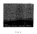
- FIG. 3 shows this antireflection film observed with the SEM.
- a solution a' was prepared similarly to the solution A except that the blend amounts were changed to 40.0 g of the dispersion of fine silica particles, 45.2 g of ethyl cellosolve, 1 g of hydrochloric acid and 13.8 g of tetraethoxyorthosilane. Then, 40 g of the solution a' was introduced in the solution b, followed by sufficient stirring, thus preparing a coating solution. Using this coating solution, an antireflection film was produced similarly to Example 1 and measured similarly to Example 1. Tables 2 and 4 show the results of the measurements. Further, FIG. 5 shows this antireflection film observed with the SEM.
- Example 1 Comp. ex. 1 Comp. ex. 2 Comp. ex. 3 Comp. ex.
- Example 1 From the comparison between Example 1 and Comparative example 2, it was found that, even when the fine particles were embedded suitably in the binder layer, the antireflection film became brittle and easier to peel off with an increase in the internal porosity of the binder layer.
- Example 1 From the comparison between Example 1 and Comparative example 1, it was found that, when the fine particles were embedded shallowly in the binder layer, the antireflection film achieved a lower reflectance owing to a decrease in its apparent refractive index caused by the formation of spaces between the fine particles but suffered from declining physical strength, resulting in easier peeling.
- Example 1 From the comparison between Example 1 and Comparative example 3, the following was found.
- the reflectance of the antireflection film slightly rises, and this state does not change very much even after increased rotations in the Taber's abrasion test.
- the antireflection film suddenly peeled off. This indicated that too many internal pores in the binder layer lowered the strength (durability) of the binder layer.
- Example 1 Similarly, from the comparison between Example 1 and Comparative examples 1 to 3, it was found that, when the internal porosity of the binder layer exceeded 50 vol%, the alkali resistance of the antireflection film became insufficient. As described above, the antireflection film of Example 1 was excellent not only in its abrasion resistance but also in its chemical durability.
- Example 1 From the comparison between Example 1 and Comparative examples 1 and 4, it was found that the antireflection film raised the short circuit current value. This indicated that it was possible to enhance the photoelectric conversion efficiency of a solar cell by forming the antireflection film.
Landscapes
- Physics & Mathematics (AREA)
- General Physics & Mathematics (AREA)
- Sustainable Development (AREA)
- Engineering & Computer Science (AREA)
- Optics & Photonics (AREA)
- Life Sciences & Earth Sciences (AREA)
- Computer Hardware Design (AREA)
- Electromagnetism (AREA)
- Condensed Matter Physics & Semiconductors (AREA)
- Microelectronics & Electronic Packaging (AREA)
- Power Engineering (AREA)
- Sustainable Energy (AREA)
- Surface Treatment Of Optical Elements (AREA)
- Photovoltaic Devices (AREA)
- Surface Treatment Of Glass (AREA)
- Photoreceptors In Electrophotography (AREA)
Applications Claiming Priority (3)
| Application Number | Priority Date | Filing Date | Title |
|---|---|---|---|
| JP2000385093 | 2000-12-19 | ||
| JP2000385093A JP2002182006A (ja) | 2000-12-19 | 2000-12-19 | 反射防止膜、それを備えた基材および光電変換装置 |
| PCT/JP2001/011111 WO2002050577A1 (fr) | 2000-12-19 | 2001-12-18 | Revetement reduisant la reflexion, materiau de base et transducteur photoelectrique pourvu de ce revetement reducteur de reflexion |
Publications (2)
| Publication Number | Publication Date |
|---|---|
| EP1363142A1 true EP1363142A1 (fr) | 2003-11-19 |
| EP1363142A4 EP1363142A4 (fr) | 2007-05-16 |
Family
ID=18852422
Family Applications (1)
| Application Number | Title | Priority Date | Filing Date |
|---|---|---|---|
| EP01271550A Withdrawn EP1363142A4 (fr) | 2000-12-19 | 2001-12-18 | Revetement reduisant la reflexion, materiau de base et transducteur photoelectrique pourvu de ce revetement reducteur de reflexion |
Country Status (4)
| Country | Link |
|---|---|
| US (1) | US20040043210A1 (fr) |
| EP (1) | EP1363142A4 (fr) |
| JP (1) | JP2002182006A (fr) |
| WO (1) | WO2002050577A1 (fr) |
Families Citing this family (15)
| Publication number | Priority date | Publication date | Assignee | Title |
|---|---|---|---|---|
| JP3908252B2 (ja) * | 2005-06-03 | 2007-04-25 | 株式会社フミン | 紫外線遮蔽剤や赤外線遮蔽剤を含有した塗膜を形成する塗装方法 |
| DE102009054630B4 (de) * | 2008-12-15 | 2013-02-14 | Qimonda Ag | Verfahren zum Herstellen eines photovoltaisches Bauelements |
| KR101072204B1 (ko) * | 2009-03-31 | 2011-10-11 | 엘지이노텍 주식회사 | 태양전지 및 이의 제조방법 |
| KR101021659B1 (ko) * | 2009-12-07 | 2011-03-17 | 주식회사 에이치와이티씨 | 태양전지 모듈용 글래스에 사용하기 위하여 광투과율을 증대시켜 주는 코팅액을 제조하는 방법과 이에 의하여 제조된 코팅액 조성물 |
| JP5412376B2 (ja) * | 2010-06-02 | 2014-02-12 | Jx日鉱日石エネルギー株式会社 | 太陽電池 |
| US20120060913A1 (en) * | 2010-09-13 | 2012-03-15 | California Institute Of Technology | Whispering gallery solar cells |
| JP5957792B2 (ja) * | 2011-01-12 | 2016-07-27 | 大日本印刷株式会社 | 反射防止フィルム、および反射防止フィルムの製造方法 |
| US9272947B2 (en) * | 2011-05-02 | 2016-03-01 | Corning Incorporated | Glass article having antireflective layer and method of making |
| JP2012230968A (ja) * | 2011-04-25 | 2012-11-22 | Hitachi Chem Co Ltd | 封止材シート及び太陽電池モジュール |
| CN104094671B (zh) * | 2012-11-29 | 2017-04-05 | 松下知识产权经营株式会社 | 带有透明导电层的基材以及有机电致发光元件 |
| CN202948938U (zh) * | 2012-11-30 | 2013-05-22 | 法国圣戈班玻璃公司 | 光学组件及光伏器件 |
| WO2014156374A1 (fr) * | 2013-03-25 | 2014-10-02 | Jsr株式会社 | Composition de formation de film inorganique pour des processus de résist à multicouches, et procédé de formation de motifs |
| US20140311569A1 (en) * | 2013-04-23 | 2014-10-23 | Huey-Liang Hwang | Solar cell with omnidirectional anti-reflection structure and method for fabricating the same |
| US9293611B1 (en) * | 2014-09-24 | 2016-03-22 | Huey-Liang Hwang | Solar cell structure and method for fabricating the same |
| JP6164258B2 (ja) * | 2015-07-13 | 2017-07-19 | 日立化成株式会社 | 太陽電池モジュール |
Citations (5)
| Publication number | Priority date | Publication date | Assignee | Title |
|---|---|---|---|---|
| JPH06155652A (ja) * | 1992-11-26 | 1994-06-03 | Nitto Denko Corp | 低反射部材 |
| JPH08211202A (ja) * | 1995-02-07 | 1996-08-20 | Hitachi Ltd | 撥水撥油性超微粒子を有する光透過板およびその製造方法 |
| US5665422A (en) * | 1991-03-19 | 1997-09-09 | Hitachi, Ltd. | Process for formation of an ultra fine particle film |
| JPH10209481A (ja) * | 1997-01-27 | 1998-08-07 | Sanyo Electric Co Ltd | 光電変換装置 |
| US5880557A (en) * | 1988-09-09 | 1999-03-09 | Hitachi, Ltd. | Transparent plate, process for the production thereof and their applied screen display plate, and cathode ray tube and process for the production thereof |
Family Cites Families (6)
| Publication number | Priority date | Publication date | Assignee | Title |
|---|---|---|---|---|
| US4535026A (en) * | 1983-06-29 | 1985-08-13 | The United States Of America As Represented By The United States Department Of Energy | Antireflective graded index silica coating, method for making |
| US5742118A (en) * | 1988-09-09 | 1998-04-21 | Hitachi, Ltd. | Ultrafine particle film, process for producing the same, transparent plate and image display plate |
| JPH06297629A (ja) * | 1993-04-20 | 1994-10-25 | Hitachi Ltd | 超微粒子膜及びその形成方法,並びに透明板及び画像表示装置 |
| JPH07168006A (ja) * | 1993-09-24 | 1995-07-04 | Dainippon Printing Co Ltd | 反射防止膜、反射防止フィルムおよびその製造方法 |
| JP4267741B2 (ja) * | 1999-03-09 | 2009-05-27 | 富士フイルム株式会社 | 防眩性反射防止フィルムおよび画像表示装置 |
| WO2001042155A1 (fr) * | 1999-12-13 | 2001-06-14 | Nippon Sheet Glass Co., Ltd. | Article en verre a faible reflexion |
-
2000
- 2000-12-19 JP JP2000385093A patent/JP2002182006A/ja active Pending
-
2001
- 2001-12-18 EP EP01271550A patent/EP1363142A4/fr not_active Withdrawn
- 2001-12-18 WO PCT/JP2001/011111 patent/WO2002050577A1/fr not_active Application Discontinuation
- 2001-12-18 US US10/450,940 patent/US20040043210A1/en not_active Abandoned
Patent Citations (5)
| Publication number | Priority date | Publication date | Assignee | Title |
|---|---|---|---|---|
| US5880557A (en) * | 1988-09-09 | 1999-03-09 | Hitachi, Ltd. | Transparent plate, process for the production thereof and their applied screen display plate, and cathode ray tube and process for the production thereof |
| US5665422A (en) * | 1991-03-19 | 1997-09-09 | Hitachi, Ltd. | Process for formation of an ultra fine particle film |
| JPH06155652A (ja) * | 1992-11-26 | 1994-06-03 | Nitto Denko Corp | 低反射部材 |
| JPH08211202A (ja) * | 1995-02-07 | 1996-08-20 | Hitachi Ltd | 撥水撥油性超微粒子を有する光透過板およびその製造方法 |
| JPH10209481A (ja) * | 1997-01-27 | 1998-08-07 | Sanyo Electric Co Ltd | 光電変換装置 |
Non-Patent Citations (1)
| Title |
|---|
| See also references of WO0250577A1 * |
Also Published As
| Publication number | Publication date |
|---|---|
| JP2002182006A (ja) | 2002-06-26 |
| EP1363142A4 (fr) | 2007-05-16 |
| WO2002050577A1 (fr) | 2002-06-27 |
| US20040043210A1 (en) | 2004-03-04 |
Similar Documents
| Publication | Publication Date | Title |
|---|---|---|
| JP4841782B2 (ja) | 低反射膜および太陽電池パネル | |
| EP1363142A1 (fr) | Revetement reduisant la reflexion, materiau de base et transducteur photoelectrique pourvu de ce revetement reducteur de reflexion | |
| EP1447433B1 (fr) | Composition de materiau de revetement et article dote d'un film de revetement forme avec cette derniere | |
| JP4527272B2 (ja) | 低反射ガラス物品 | |
| EP1984764B1 (fr) | Procédé pour la préparation d'un article avec des propriétés anti-réflective et article obtenable. | |
| US5858526A (en) | Composite material with a high refractive index, process for producing said composite material and optically active material incorporating said composite material | |
| JP5063926B2 (ja) | 反射防止基材の製造方法 | |
| JP4330661B2 (ja) | 高屈折率と機械的耐磨耗性を有する酸化タンタルベースの無機ポリマー材料、その製法、および当該ポリマーを含む光学材料 | |
| EP2657011A1 (fr) | Article doté d'un film à faible réflexion | |
| JP4224646B2 (ja) | 紫外線に対する露光による架橋結合/高密度化を使用して多層光材料を製造する方法と当該方法で製造された光材料 | |
| JP4048912B2 (ja) | 表面防汚性複合樹脂フィルム、表面防汚性物品、化粧板 | |
| US10908320B2 (en) | Coated glass sheet and method for producing same | |
| WO2013001975A1 (fr) | Solution de revêtement inorganique hydrophile, film de revêtement hydrophile obtenu à partir de celle-ci et élément l'utilisant | |
| JPH08508582A (ja) | 光学特性および耐摩耗性を有する薄層被覆層の形成方法 | |
| Yamaguchi et al. | Anti-reflective coatings of flowerlike alumina on various glass substrates by the sol–gel process with the hot water treatment | |
| JP2002365403A (ja) | 低反射膜およびこれを用いた透明積層体 | |
| JP2012148952A (ja) | 低反射膜形成用塗布液およびその調製方法およびそれを用いた低反射部材 | |
| WO2007081025A1 (fr) | Plaque de verre pour véhicule pourvue d'un film et son procédé de fabrication | |
| JP2003054996A (ja) | 反射抑制膜およびこれを備えた透明基体 | |
| JP2005330172A (ja) | ガラス板およびその製造方法、低反射性透明ガラス板、低反射性透明導電基板およびその製造方法、ならびに、低反射性透明導電基板を用いた光電変換素子 | |
| JP3649596B2 (ja) | 親水性酸化物被膜を形成した基材およびその製造方法 | |
| JP3400259B2 (ja) | 親水性被膜およびその製造方法 | |
| JP7083342B2 (ja) | 低反射膜付き透明基板、光電変換装置、低反射膜付き透明基板の低反射膜を形成するための塗工液及び低反射膜付き透明基板の製造方法 | |
| JP2011119626A (ja) | 低反射膜で被覆してなる太陽電池パネル用カバーガラス及びその製法 | |
| WO2022113108A1 (fr) | Procédé de production de revêtements monocouches omnidirectionnels antireflets à large bande et super hydrophiles (antibuée) pour applications solaires et autres |
Legal Events
| Date | Code | Title | Description |
|---|---|---|---|
| PUAI | Public reference made under article 153(3) epc to a published international application that has entered the european phase |
Free format text: ORIGINAL CODE: 0009012 |
|
| 17P | Request for examination filed |
Effective date: 20030718 |
|
| AK | Designated contracting states |
Kind code of ref document: A1 Designated state(s): AT BE CH CY DE DK ES FI FR GB GR IE IT LI LU MC NL PT SE TR |
|
| RBV | Designated contracting states (corrected) |
Designated state(s): DE GB |
|
| A4 | Supplementary search report drawn up and despatched |
Effective date: 20070418 |
|
| 17Q | First examination report despatched |
Effective date: 20070706 |
|
| STAA | Information on the status of an ep patent application or granted ep patent |
Free format text: STATUS: THE APPLICATION IS DEEMED TO BE WITHDRAWN |
|
| 18D | Application deemed to be withdrawn |
Effective date: 20080117 |