EP1362990A2 - Hubventilsteuerungseinrichtung - Google Patents
Hubventilsteuerungseinrichtung Download PDFInfo
- Publication number
- EP1362990A2 EP1362990A2 EP03006990A EP03006990A EP1362990A2 EP 1362990 A2 EP1362990 A2 EP 1362990A2 EP 03006990 A EP03006990 A EP 03006990A EP 03006990 A EP03006990 A EP 03006990A EP 1362990 A2 EP1362990 A2 EP 1362990A2
- Authority
- EP
- European Patent Office
- Prior art keywords
- fluid
- valve
- engine
- control valve
- intake
- Prior art date
- Legal status (The legal status is an assumption and is not a legal conclusion. Google has not performed a legal analysis and makes no representation as to the accuracy of the status listed.)
- Withdrawn
Links
- 239000012530 fluid Substances 0.000 claims abstract description 211
- 238000004891 communication Methods 0.000 claims abstract description 3
- 239000003570 air Substances 0.000 claims description 18
- 230000006835 compression Effects 0.000 claims description 11
- 238000007906 compression Methods 0.000 claims description 11
- 238000000034 method Methods 0.000 claims description 5
- 239000012080 ambient air Substances 0.000 claims description 2
- 239000002826 coolant Substances 0.000 claims description 2
- 238000002485 combustion reaction Methods 0.000 description 13
- 230000033001 locomotion Effects 0.000 description 8
- 239000000446 fuel Substances 0.000 description 7
- 230000009467 reduction Effects 0.000 description 5
- GQPLMRYTRLFLPF-UHFFFAOYSA-N Nitrous Oxide Chemical compound [O-][N+]#N GQPLMRYTRLFLPF-UHFFFAOYSA-N 0.000 description 4
- VNWKTOKETHGBQD-UHFFFAOYSA-N methane Chemical compound C VNWKTOKETHGBQD-UHFFFAOYSA-N 0.000 description 4
- 238000013459 approach Methods 0.000 description 3
- 239000000203 mixture Substances 0.000 description 3
- 238000011144 upstream manufacturing Methods 0.000 description 3
- 230000000712 assembly Effects 0.000 description 2
- 238000000429 assembly Methods 0.000 description 2
- 230000003247 decreasing effect Effects 0.000 description 2
- 239000002283 diesel fuel Substances 0.000 description 2
- 230000006870 function Effects 0.000 description 2
- 239000007789 gas Substances 0.000 description 2
- 239000003502 gasoline Substances 0.000 description 2
- 238000005461 lubrication Methods 0.000 description 2
- 239000003345 natural gas Substances 0.000 description 2
- 239000001272 nitrous oxide Substances 0.000 description 2
- 230000010355 oscillation Effects 0.000 description 2
- 230000004044 response Effects 0.000 description 2
- 230000004043 responsiveness Effects 0.000 description 2
- 230000001953 sensory effect Effects 0.000 description 2
- 230000009471 action Effects 0.000 description 1
- 230000002411 adverse Effects 0.000 description 1
- 230000009286 beneficial effect Effects 0.000 description 1
- 230000005540 biological transmission Effects 0.000 description 1
- 230000003750 conditioning effect Effects 0.000 description 1
- 238000013461 design Methods 0.000 description 1
- 238000002347 injection Methods 0.000 description 1
- 239000007924 injection Substances 0.000 description 1
- 238000012986 modification Methods 0.000 description 1
- 230000004048 modification Effects 0.000 description 1
- 238000011160 research Methods 0.000 description 1
Images


Classifications
-
- F—MECHANICAL ENGINEERING; LIGHTING; HEATING; WEAPONS; BLASTING
- F01—MACHINES OR ENGINES IN GENERAL; ENGINE PLANTS IN GENERAL; STEAM ENGINES
- F01L—CYCLICALLY OPERATING VALVES FOR MACHINES OR ENGINES
- F01L13/00—Modifications of valve-gear to facilitate reversing, braking, starting, changing compression ratio, or other specific operations
- F01L13/06—Modifications of valve-gear to facilitate reversing, braking, starting, changing compression ratio, or other specific operations for braking
-
- F—MECHANICAL ENGINEERING; LIGHTING; HEATING; WEAPONS; BLASTING
- F01—MACHINES OR ENGINES IN GENERAL; ENGINE PLANTS IN GENERAL; STEAM ENGINES
- F01L—CYCLICALLY OPERATING VALVES FOR MACHINES OR ENGINES
- F01L9/00—Valve-gear or valve arrangements actuated non-mechanically
- F01L9/10—Valve-gear or valve arrangements actuated non-mechanically by fluid means, e.g. hydraulic
- F01L9/11—Valve-gear or valve arrangements actuated non-mechanically by fluid means, e.g. hydraulic in which the action of a cam is being transmitted to a valve by a liquid column
- F01L9/12—Valve-gear or valve arrangements actuated non-mechanically by fluid means, e.g. hydraulic in which the action of a cam is being transmitted to a valve by a liquid column with a liquid chamber between a piston actuated by a cam and a piston acting on a valve stem
-
- F—MECHANICAL ENGINEERING; LIGHTING; HEATING; WEAPONS; BLASTING
- F01—MACHINES OR ENGINES IN GENERAL; ENGINE PLANTS IN GENERAL; STEAM ENGINES
- F01L—CYCLICALLY OPERATING VALVES FOR MACHINES OR ENGINES
- F01L1/00—Valve-gear or valve arrangements, e.g. lift-valve gear
- F01L1/34—Valve-gear or valve arrangements, e.g. lift-valve gear characterised by the provision of means for changing the timing of the valves without changing the duration of opening and without affecting the magnitude of the valve lift
- F01L1/344—Valve-gear or valve arrangements, e.g. lift-valve gear characterised by the provision of means for changing the timing of the valves without changing the duration of opening and without affecting the magnitude of the valve lift changing the angular relationship between crankshaft and camshaft, e.g. using helicoidal gear
- F01L1/3442—Valve-gear or valve arrangements, e.g. lift-valve gear characterised by the provision of means for changing the timing of the valves without changing the duration of opening and without affecting the magnitude of the valve lift changing the angular relationship between crankshaft and camshaft, e.g. using helicoidal gear using hydraulic chambers with variable volume to transmit the rotating force
- F01L2001/34423—Details relating to the hydraulic feeding circuit
- F01L2001/34446—Fluid accumulators for the feeding circuit
-
- F—MECHANICAL ENGINEERING; LIGHTING; HEATING; WEAPONS; BLASTING
- F02—COMBUSTION ENGINES; HOT-GAS OR COMBUSTION-PRODUCT ENGINE PLANTS
- F02B—INTERNAL-COMBUSTION PISTON ENGINES; COMBUSTION ENGINES IN GENERAL
- F02B2275/00—Other engines, components or details, not provided for in other groups of this subclass
- F02B2275/32—Miller cycle
-
- Y—GENERAL TAGGING OF NEW TECHNOLOGICAL DEVELOPMENTS; GENERAL TAGGING OF CROSS-SECTIONAL TECHNOLOGIES SPANNING OVER SEVERAL SECTIONS OF THE IPC; TECHNICAL SUBJECTS COVERED BY FORMER USPC CROSS-REFERENCE ART COLLECTIONS [XRACs] AND DIGESTS
- Y02—TECHNOLOGIES OR APPLICATIONS FOR MITIGATION OR ADAPTATION AGAINST CLIMATE CHANGE
- Y02T—CLIMATE CHANGE MITIGATION TECHNOLOGIES RELATED TO TRANSPORTATION
- Y02T10/00—Road transport of goods or passengers
- Y02T10/10—Internal combustion engine [ICE] based vehicles
- Y02T10/12—Improving ICE efficiencies
Definitions
- the present invention is directed to an engine valve actuation system. More particularly, the present invention is directed to a valve actuation system for an internal combustion engine.
- an internal combustion engine such as, for example, a diesel, gasoline, or natural gas engine
- emissions which may include particulates and nitrous oxide (NOx)
- NOx nitrous oxide
- An exhaust stroke of an engine piston forces exhaust gas, which may include these emissions from the engine. If no emission reduction measures are in place, these undesirable emissions will eventually be exhausted to the environment.
- actuation timing of the engine valves For example, the actuation timing of the intake and exhaust valves may be modified to implement a variation on the typical diesel or Otto cycle known as the Miller cycle. In a "late intake" type Miller cycle, the intake valves of the engine are held open during a portion of the compression stroke of the piston.
- the engine valves in an internal combustion engine are typically driven by a cam arrangement that is operatively connected to the crankshaft of the engine.
- the rotation of the crankshaft results in a corresponding rotation of a cam that drives one or more cam followers.
- the movement of the cam followers results in the actuation of the engine valves.
- the shape of the cam governs the timing and duration of the valve actuation.
- a "late intake" Miller cycle may be implemented in such a cam arrangement by modifying the shape of the cam to overlap the actuation of the intake valve with the start of the compression stroke of the piston.
- a late intake Miller cycle may be undesirable under certain operating conditions.
- a diesel engine operating on a late intake Miller cycle will be difficult to start when the engine is cold. This difficulty arises because diesel fuel combustion is achieved when an air and fuel mixture is pressurized to a certain level.
- Implementation of the late intake Miller cycle reduces the amount of air and the amount of compression within each combustion chamber. The reduced compression combined with the reduced temperature of the engine results in a lower maximum pressure level of the air and fuel mixture.
- achieving combustion in a cold engine operating on a late intake Miller cycle may prove difficult.
- the actuation timing of a valve system driven by a cam arrangement is determined by the shape of the driving cam. Because the shape of the cam is fixed, this arrangement is inflexible and may not be changed during the operation of the engine. In other words, a conventional cam driven valve actuation system may not be modified to account for different operating conditions of the engine.
- the intake valve actuation system of the present invention solves one or more of the problems set forth above.
- the present invention is directed to an engine valve actuation system that includes an intake valve moveable between a first position to prevent a flow of fluid and a second position to allow a flow of fluid.
- a cam assembly is connected to move the intake valve between the first position and the second position.
- a fluid actuator is configured to selectively prevent the intake valve from moving to the first position.
- a source of fluid is in fluid communication with the fluid actuator.
- a directional control valve is configured to control a flow of fluid between the source of fluid and the fluid actuator.
- a control valve is disposed between the source of fluid and the directional control valve. The control valve is moveable between a first position to prevent the flow of fluid between the source of fluid and the directional control valve and a second position to allow the flow of fluid from the source of fluid to the directional control valve.
- the present invention is directed to a method of controlling an engine having a piston moveable through an intake stroke and a compression stroke.
- a cam is rotated to move an intake valve between a first position to prevent a flow of fluid and a second position to allow a flow of fluid during the intake stroke of the piston.
- Fluid is directed through a control valve to a fluid actuator associated with the intake valve when the intake valve is removed from the first position.
- a directional control valve is actuated to selectively prevent fluid from flowing from the fluid actuator to thereby prevent the intake valve from moving to the first position during at least a portion of the compression stroke of the piston.
- At least one operating parameter of the engine is sensed.
- the control valve is moved to a closed position to prevent fluid from flowing to the directional control valve and the fluid actuator based on the sensed operating parameter of the engine.
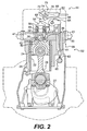
- engine 20 is depicted and described as a four stroke diesel engine.
- engine 20 may be any other type of internal combustion engine, such as, for example, a gasoline or natural gas engine.
- engine 20 includes an engine block 28 that defines a plurality of cylinders 22.
- a piston 24 is slidably disposed within each cylinder 22.
- engine 20 includes six cylinders 22 and six associated pistons 24.
- engine 20 may include a greater or lesser number of pistons 24 and that pistons 24 may be disposed in an "in-line” configuration, a "V" configuration, or any other conventional configuration.
- engine 20 includes a crankshaft 27 that is rotatably disposed within engine block 28.
- a connecting rod 26 connects each piston 24 to crankshaft 27.
- Each piston 24 is coupled to crankshaft 27 so that a sliding motion of piston 24 within the respective cylinder 22 results in a rotation of crankshaft 27. Similarly, a rotation of crankshaft 27 will result in a sliding motion of piston 24.
- Engine 20 also includes a cylinder head 30.
- Cylinder head 30 defines an intake passageway 41 that leads to at least one intake port 36 for each cylinder 22. Cylinder head 30 may further define two or more intake ports 36 for each cylinder 22.
- An intake valve 32 is disposed within each intake port 36.
- Intake valve 32 includes a valve element 40 that is configured to selectively block intake port 36. As described in greater detail below, each intake valve 32 may be actuated to move or "lift" valve element 40 to thereby open the respective intake port 36.
- the pair of intake valves 32 may be actuated by a single valve actuation assembly or by a pair of valve actuation assemblies.
- Cylinder head 30 also defines at least one exhaust port 38 for each cylinder 22. Each exhaust port 38 leads from the respective cylinder 22 to an exhaust passageway 43. Cylinder head 30 may further define two or more exhaust ports 38 for each cylinder 22.
- An exhaust valve 34 is disposed within each exhaust port 38.
- Exhaust valve 34 includes a valve element 48 that is configured to selectively block exhaust port 38. As described in greater detail below, each exhaust valve 34 may be actuated to move or "lift" valve element 48 to thereby open the respective exhaust port 38.
- the pair of exhaust valves 34 may be actuated by a single valve actuation assembly or by a pair of valve actuation assemblies.
- Fig. 2 illustrates an exemplary embodiment of one cylinder 22 of engine 20.
- cylinder head 30 defines a pair of intake ports 36 connecting intake passageway 41 to cylinder 22.
- Each intake port 36 includes a valve seat 50.
- One intake valve 32 is disposed within each intake port 36.
- Valve element 40 of intake valve 32 is configured to engage valve seat 50. When intake valve 32 is in a closed position, valve element 40 engages valve seat 50 to close intake port 36 and blocks fluid flow relative to cylinder 22. When intake valve 32 is lifted from the closed position, intake valve 32 allows a flow of fluid relative to cylinder 22.
- cylinder head 30 may define two or more exhaust ports 38 (only one of which is illustrated in Fig. 1) that connect cylinder 22 with exhaust passageway 43.
- One exhaust valve 34 is disposed within each exhaust port 38.
- a valve element 48 of each exhaust valve 34 is configured to close exhaust port 38 when exhaust valve 34 is in a closed position and block fluid flow relative to cylinder 22.
- exhaust valve 32 allows a flow of fluid relative to cylinder 22.
- Valve actuation assembly 44 is operatively associated with intake valves 32.
- Valve actuation assembly 44 includes a bridge 54 that is connected to each valve element 40 through a pair of valve stems 46.
- a spring 56 may be disposed around each valve stem 46 between cylinder head 30 and bridge 54. Spring 56 acts to bias both valve elements 40 into engagement with the respective valve seat 50 to thereby close each intake port 36.
- Valve actuation assembly 44 also includes a rocker arm 64.
- Rocker arm 64 is configured to pivot about a pivot 66.
- One end 68 of rocker arm 64 is connected to bridge 54.
- the opposite end of rocker arm 64 is connected to a cam assembly 52.
- cam assembly 52 includes a cam 60 having a cam lobe and mounted on a cam shaft, a push rod 61, and a cam follower 62.
- cam assembly 52 may have other configurations, such as, for example, where cam 60 acts directly on rocker arm 64.
- Valve actuation assembly 44 may be driven by cam 60.
- Cam 60 is connected to crankshaft 27 so that a rotation of crankshaft 27 induces a corresponding rotation of cam 60.
- Cam 60 may be connected to crankshaft 27 through any means readily apparent to one skilled in the art, such as, for example, through a gear reduction assembly (not shown).
- a rotation of cam 60 will cause cam follower 62 and associated push rod 61 to periodically reciprocate between an upper and a lower position.
- rocker arm 64 The reciprocating movement of push rod 61 causes rocker arm 64 to pivot about pivot 66.
- rocker arm 64 When push rod 61 moves in the direction indicated by arrow 58, rocker arm 64 will pivot and move bridge 54 in the opposite direction.
- the movement of bridge 54 causes each intake valve 32 to lift and open intake ports 36.
- springs 56 will act on bridge 54 to return each intake valve 32 to the closed position.
- cam 60 controls the timing of the actuation of intake valves 32.
- cam 60 may be configured to coordinate the actuation of intake valves 32 with the movement of piston 24.
- intake valves 32 may be actuated to open intake ports 36 when piston 24 is withdrawing within cylinder 22 to allow air to flow from intake passageway 41 into cylinder 22.
- a similar valve actuation assembly may be connected to exhaust valves 34.
- a second cam (not shown) may be connected to crankshaft 27 to control the actuation timing of exhaust valves 34.
- Exhaust valves 34 may be actuated to open exhaust ports 38 when piston 24 is advancing within cylinder 22 to allow exhaust to flow from cylinder 22 into exhaust passageway 43.
- valve actuation assembly 44 also includes a fluid actuator 70.
- Fluid actuator 70 includes an actuator cylinder 72 that defines an actuator chamber 76.
- An actuator piston 74 is slidably disposed within actuator cylinder 72 and is connected to an actuator rod 78.
- a return spring (not shown) may act on actuator piston 74 to return actuator piston 74 to a home position.
- Actuator rod 78 is engageable with an end 68 of rocker arm 64.
- a fluid line 80 is connected to actuator chamber 76. Pressurized fluid may be directed through fluid line 80 into actuator chamber 76 to move actuator piston 74 within actuator cylinder 72. Movement of actuator piston 74 causes actuator rod 78 to engage end 68 of rocker arm 64. Fluid may be introduced to actuator chamber 76 when intake valves 32 are in the open position to move actuator rod 78 into engagement with rocker arm 64 to thereby hold intake valves 32 in the open position. Alternatively, fluid may be introduced to actuator chamber 76 when intake valves 32 are in the closed position to move actuator rod 78 into engagement with rocker arm 64 and pivot rocker arm 64 about pivot 66 to thereby open intake valves 32.
- a source of fluid 84 which is connected to a tank 87, supplies pressurized fluid to fluid actuator 70.
- Tank 87 may store any type of fluid readily apparent to one skilled in the art, such as, for example, hydraulic fluid, fuel, or transmission fluid.
- Source of fluid 84 may be part of a lubrication system, such as typically accompanies an internal combustion engine. Such a lubrication system may provide pressurized oil having a pressure of, for example, less than 700 KPa (100 psi) or, more particularly, between about 210 KPa and 620 KPa (30 psi and 90 psi).
- the source of fluid may be a pump configured to provide oil at a higher pressure, such as, for example, between about 10 MPa and 35 MPa (1450 psi and 5000 psi).
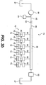
- a fluid supply system 79 connects source of fluid 84 with fluid actuator 70.
- source of fluid 84 is connected to a fluid rail 86 through fluid line 85.
- a control valve 82 is disposed in fluid line 85. Control valve 82 may be opened to allow pressurized fluid to flow from source of fluid 84 to fluid rail 86. Control valve 82 may be closed to prevent pressurized fluid from flowing from source of fluid 84 to fluid rail 86.
- fluid rail 86 supplies pressurized fluid from source of fluid 84 to a series of fluid actuators 70.
- Each fluid actuator 70 may be associated with either the intake valves 32 or the exhaust valves 34 of a particular engine cylinder 22 (referring to Fig. 1).
- Fluid lines 80 direct pressurized fluid from fluid rail 86 into the actuator chamber 76 of each fluid actuator 70.
- a directional control valve 88 may be disposed in each fluid line 80. Each directional control valve 88 may be opened to allow pressurized fluid to flow between fluid rail 86 and actuator chamber 76. Each directional control valve 88 may be closed to prevent pressurized fluid from flowing between fluid rail 86 and actuator chamber 76. Directional control valve 88 may be normally biased into a closed position and actuated to allow fluid to flow through directional control valve 88. Alternatively, directional control valve 88 may be normally biased into an open position and actuated to prevent fluid from flowing through directional control valve 88.
- directional control valve 88 may be any type of controllable valve, such as, for example a two coil latching valve.
- fluid supply system 79 may have a variety of different configurations.
- a restrictive orifice 83 may be positioned in fluid line 85 between source of fluid 84 and a first end of fluid rail 86.
- Control valve 82 may be connected to an opposite end of fluid rail 86 and lead to tank 87.
- Control valve 82 may be opened to allow a flow of fluid through restrictive orifice 83 and fluid rail 86 to tank 87.
- Control valve 82 may be closed to allow a build up of pressure in the fluid within fluid rail 86.
- fluid supply system 79 may include a check valve 94 placed in parallel with directional control valve 88 between control valve 82 and fluid actuator 70.
- Check valve 94 may be configured to allow fluid to flow in the direction from control valve 82 to fluid actuator 70.
- fluid supply system 79 may include an air bleed valve 96.
- Air bleed valve 96 may be any device readily apparent to one skilled in the art as capable of allowing air to escape a hydraulic system.
- air bleed valve 96 may be a spring biased ball valve that allows air to flow through the valve, but closes when exposed to fluid pressure.
- a snubbing valve 98 may be disposed in fluid line 81 leading to actuator chamber 76. Snubbing valve 98 may be configured to restrict the flow of fluid through fluid line 81. For example, snubbing valve 98 may be configured to decrease the rate at which fluid exits actuator chamber 76 to thereby slow the rate at which intake valve 32 closes.
- Fluid supply system 79 may also include an accumulator 95.
- a restrictive orifice 93 may be disposed in the inlet to accumulator 95. As described in greater detail below, the combination of accumulator 95 and restrictive orifice 93 act to dampen oscillations in actuator chamber 76 and fluid line 80, which may cause actuator piston 74 to oscillate.
- fluid supply system 79 includes a source of high pressure fluid 92.
- Directional control valve 88 is configured to selectively connect either source of pressure fluid 84 or source of high pressure fluid 92 with fluid line 81. In this manner, either low or high pressure fluid may be directed to fluid actuator 70 to meet the needs of the current operating conditions.
- Directional control valve 88 may be normally biased into a position where source of fluid 84 is connected with fluid line 81.
- Controller 100 is connected to each valve actuation assembly 44 and to control valve 82.
- Controller 100 may include an electronic control module that has a microprocessor and a memory.
- the memory is connected to the microprocessor and stores an instruction set and variables.
- various other known circuits such as, for example, power supply circuitry, signal conditioning circuitry, and solenoid driver circuitry, among others.
- Controller 100 may be programmed to control one or more aspects of the operation of engine 20.
- controller 100 may be programmed to control the valve actuation assembly, the fuel injection system, and any other function readily apparent to one skilled in the art.
- Controller 100 may control engine 20 based on the current operating conditions of the engine and/or instructions received from an operator.
- Controller 100 may be further programmed to receive information from one or more sensors operatively connected with engine 20.
- Each of the sensors may be configured to sense one or more operational parameters of engine 20.
- a sensor 90 may be connected with fluid supply system 79 to sense the temperature of the fluid within fluid supply system 79.
- engine 20 may be equipped with sensors configured to sense one or more of the following: the temperature of the engine coolant, the temperature of the engine, the ambient air temperature, the engine speed, the load on the engine, and the intake air pressure.
- Engine 20 may be further equipped with a sensor configured to monitor the crank angle of crankshaft 27 to thereby determine the position of pistons 24 within their respective cylinders 22.
- the crank angle of crankshaft 27 is also related to actuation timing of intake valves 32 and exhaust valves 34.
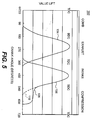
- An exemplary graph 102 indicating the relationship between valve actuation timing and crank angle is illustrated in Fig. 5. As shown by graph 102, exhaust valve actuation 104 is timed to substantially coincide with the exhaust stroke of piston 24 and intake valve actuation 106 is timed to substantially coincide with the intake stroke of piston 24.
- controller 100 may operate each valve actuation assembly 44 to selectively implement a late intake Miller cycle for each cylinder 22 of engine 20. Under normal operating conditions, implementation of the late intake Miller cycle will increase the overall efficiency of the engine 20. Under some operating conditions, such as, for example, when engine 20 is cold, controller 100 may operate engine 20 on a conventional diesel cycle.
- controller 100 implements a late intake Miller cycle by selectively actuating fluid actuator 70 to hold intake valve 32 open for a first portion of the compression stroke of piston 24. This may be accomplished by moving control valve 82 and directional control valve 88 to the open positions when piston 24 starts an intake stroke. This allows pressurized fluid to flow from source of fluid 84 through fluid rail 86 and into actuator chamber 76. The force of the fluid entering actuator chamber 76 moves actuator piston 74 so that actuator rod 78 follows end 68 of rocker arm 64 as rocker arm 64 pivots to open intake valves 32. The distance and rate of movement of actuator rod 78 will depend upon the configuration of actuator chamber 76 and fluid supply system 79. When actuator chamber 76 is filled with fluid and rocker arm 64 returns intake valves 32 from the open position to the closed position, actuator rod 78 will engage end 68 of rocker arm 64.
- Fluid supply system 79 may be configured to supply a flow rate of fluid to fluid actuator 70 to fill actuator chamber 76 before cam 60 returns intake valves 32 to the closed position.
- pressurized fluid may flow through both directional control valve 88 and check valve 94 into actuator chamber 76.
- directional control valve 88 may remain in a closed position and fluid may flow through check valve 94 into actuator cylinder 76.
- controller 100 may close directional control valve 88. This prevents fluid from escaping from actuator chamber 76.
- actuator rod 78 will engage end 68 of rocker arm and prevent intake valves 32 from closing.
- directional control valve 88 remains in the closed position, the trapped fluid in actuator chamber 76 will prevent springs 56 from returning intake valves 32 to the closed position.
- fluid actuator 70 will hold intake valves 32 in the open position, independently of the action of cam assembly 52.
- Controller 100 may close intake valves 32 by opening directional control valve 88. This allows the pressurized fluid to flow out of actuator chamber 76. The force of springs 56 forces the fluid from actuator chamber 76, thereby allowing actuator piston 74 to move within actuator cylinder 72. This allows rocker arm 64 to pivot so that intake valves 32 are moved to the closed position. Snubbing valve 98 may restrict the rate at which fluid exits actuator chamber 76 to reduce the velocity at which intake valves 32 are closed. This may prevent valve elements 40 from being damaged when closing intake ports 36.
- FIG. 5 An exemplary late intake closing 108 is illustrated in Fig. 5. As shown, the intake valve actuation 106 is extended into a portion of the compression stroke of piston 24. This allows some of the air in cylinder 22 to escape. The amount of air allowed to escape cylinder 22 may be controlled by adjusting the crank angle at which directional control valve 88 is opened. Directional control valve 88 may be closed at an earlier crank angle to decrease the amount of escaping air or at a later crank angle to increase the amount of escaping air.
- controller 100 may disengage the late intake Miller cycle by closing control valve 82.
- Control valve 82 may be closed when controller 100 receives sensory input indicating that engine 20 is starting or is operating under cold conditions. Closing control valve 82 prevents fluid from flowing from source of fluid 84 into actuator chamber 76. Without the introduction of fluid to actuator chamber 76, fluid actuator 70 will not prevent intake valves 32 from returning to the closed position in response to the force of springs 56.
- intake valves 32 will follow a conventional diesel cycle as governed by cam 60.
- intake valve actuation 106 will follow a conventional closing 110.
- the closing of intake valves 32 substantially coincides with the end of the intake stroke of piston 24.
- no air will be forced from cylinder 22 during the compression stroke. This results in piston 24 compressing the fuel and air mixture to a higher pressure, which will facilitate diesel fuel combustion. This is particularly beneficial when engine 20 is operating in cold conditions.
- controller 100 may disengage the Miller cycle by opening control valve 82.
- Control valve 82 may be opened when controller 100 receives sensory input indicating that engine 20 is starting or is operating under cold conditions. Opening control valve 82 allows fluid to flow through restrictive orifice 83 and fluid rail 86 to tank 87. Opening control valve 82 may therefore reduce the pressure of the fluid within fluid rail 86. The decreased pressure of the fluid within fluid rail 86 may not generated a force having a force great enough to move actuator piston 74. Thus, fluid actuator 70 will not engage intake valve 32 to prevent intake valve from closing. Accordingly, engine 20 will operate on a conventional diesel cycle as governed by cam 60.
- Opening control valve 82 may also increase the responsiveness of valve actuator 70 when engine 20 is starting or operating under cold conditions. If the fluid within fluid rail 86 is cold, the fluid will have an increased viscosity. The increased viscosity of the fluid may decrease the rate at which the fluid may flow into and out of actuator chamber 76 and thereby impact the operation of valve actuator 70. By opening control valve 82, the cold fluid may be replaced by warmer fluid from source of fluid 84. This may decrease the viscosity of the fluid within fluid rail 86, which may increase the responsiveness of valve actuator 70 when control valve 82 is closed to operate engine 20 on the Miller cycle.
- Restrictive orifice 83 may ensure that the pressure of the fluid upstream of restrictive orifice 83, i.e. between source of fluid 84 and restrictive orifice 83, does not decrease when control valve 82 is opened.
- Restrictive orifice 83 may create a smaller opening than is created by the opening of control valve 82.
- the opening of control valve 82 allows fluid to flow out of fluid rail 86 at a faster rate than restrictive orifice 83 allows fluid to flow into fluid rail 86.
- opening control valve 82 will not impact the pressure of fluid upstream of restrictive orifice 83.
- the present invention provides an engine valve actuation system that may selectively alter the timing of the intake and/or exhaust valve actuation of an internal combustion engine.
- the actuation of the engine valves may be based on sensed operating conditions of the engine.
- the engine valve actuation system may implement a late intake Miller cycle when the engine is operating under normal operating conditions.
- the late intake Miller cycle may be disengaged when the engine is operating under adverse operating conditions, such as when the engine is cold.
- the present invention provides a flexible engine valve actuation system that provides for both enhanced cold starting capability and fuel efficiency gains.
Landscapes
- Engineering & Computer Science (AREA)
- Mechanical Engineering (AREA)
- General Engineering & Computer Science (AREA)
- Valve Device For Special Equipments (AREA)
- Valve-Gear Or Valve Arrangements (AREA)
- Electrical Control Of Air Or Fuel Supplied To Internal-Combustion Engine (AREA)
- Combined Controls Of Internal Combustion Engines (AREA)
- Output Control And Ontrol Of Special Type Engine (AREA)
Applications Claiming Priority (2)
| Application Number | Priority Date | Filing Date | Title |
|---|---|---|---|
| US144062 | 1998-08-31 | ||
| US10/144,062 US7069887B2 (en) | 2002-05-14 | 2002-05-14 | Engine valve actuation system |
Publications (2)
| Publication Number | Publication Date |
|---|---|
| EP1362990A2 true EP1362990A2 (de) | 2003-11-19 |
| EP1362990A3 EP1362990A3 (de) | 2007-10-17 |
Family
ID=29269716
Family Applications (1)
| Application Number | Title | Priority Date | Filing Date |
|---|---|---|---|
| EP03006990A Withdrawn EP1362990A3 (de) | 2002-05-14 | 2003-03-27 | Hubventilsteuerungseinrichtung |
Country Status (3)
| Country | Link |
|---|---|
| US (2) | US7069887B2 (de) |
| EP (1) | EP1362990A3 (de) |
| JP (1) | JP2003328715A (de) |
Cited By (2)
| Publication number | Priority date | Publication date | Assignee | Title |
|---|---|---|---|---|
| WO2010034643A1 (de) * | 2008-09-26 | 2010-04-01 | Schaeffler Kg | Elektrohydraulische ventilsteuerung |
| EP2060754A3 (de) * | 2007-11-14 | 2010-05-05 | Schaeffler KG | Hydraulikeinheit für einen Zylinderkopf einer Brennkraftmaschine mit hydraulisch variablem Ventiltrieb |
Families Citing this family (14)
| Publication number | Priority date | Publication date | Assignee | Title |
|---|---|---|---|---|
| US7228826B2 (en) * | 2003-12-23 | 2007-06-12 | Caterpillar Inc | Internal combustion engine valve seating velocity control |
| JP4534147B2 (ja) * | 2005-03-22 | 2010-09-01 | アイシン精機株式会社 | オイル供給装置 |
| US7464681B2 (en) * | 2006-02-28 | 2008-12-16 | Caterpillar Inc. | Engine and engine control method |
| US7685976B2 (en) * | 2006-03-24 | 2010-03-30 | Gm Global Technology Operations, Inc. | Induction tuning using multiple intake valve lift events |
| EP2039892B1 (de) * | 2006-06-30 | 2012-03-21 | Komatsu Ltd. | Motorventilvorrichtung |
| US7677212B2 (en) * | 2006-06-30 | 2010-03-16 | Eaton Corporation | Added motion hydraulic circuit with proportional valve |
| ES2318714T3 (es) * | 2006-12-20 | 2009-05-01 | C.R.F. Societa Consortile Per Azioni | Motor de combustion interna que presenta unas valvulas de admision con un accionamiento variable y un perfil de elevacion que incluye una parte de elevacion constante de arranque. |
| US7389762B1 (en) * | 2007-04-25 | 2008-06-24 | Ford Global Technologies, Llc | System and method for controlling valve actuators |
| EP2055906A1 (de) * | 2007-10-31 | 2009-05-06 | Caterpillar Motoren GmbH & Co. KG | Vorrichtung und Verfahren zur Ventilsteuerung |
| US8631775B2 (en) | 2010-07-28 | 2014-01-21 | General Electric Company | Multi-mode valve control mechanism for cam-driven poppet valves |
| CN101929365B (zh) * | 2010-07-30 | 2012-07-04 | 天津大学 | 柴油机液压式自适应气门正时可变系统与控制方法 |
| KR101439035B1 (ko) * | 2013-06-17 | 2014-09-05 | 현대자동차주식회사 | 차량의 가변 밸브 구동 장치 |
| DE102015013794A1 (de) * | 2015-10-22 | 2017-04-27 | Man Truck & Bus Ag | Verfahren zum Betreiben einer Brennkraftmaschine, insbesondere eines Dieselmotors |
| JP7751081B2 (ja) * | 2021-09-10 | 2025-10-07 | ジェイコブス ビークル システムズ、インコーポレイテッド | 2段階バルブ閉鎖ロッカーアセンブリ |
Citations (1)
| Publication number | Priority date | Publication date | Assignee | Title |
|---|---|---|---|---|
| US6237551B1 (en) | 1997-02-04 | 2001-05-29 | C.R.F. Societa Consortile Per Azioni | Multi-cylinder diesel engine with variable valve actuation |
Family Cites Families (127)
| Publication number | Priority date | Publication date | Assignee | Title |
|---|---|---|---|---|
| GB1062983A (en) * | 1962-12-21 | 1967-03-22 | Perkins Engines Ltd | Pressure charging system for internal combustion engines |
| US3534655A (en) * | 1968-10-01 | 1970-10-20 | Gleason Works | Control arrangements for bevel gear making machines |
| US4033304A (en) * | 1974-06-14 | 1977-07-05 | David Luria | Piston-type internal combustion engine |
| US4020809A (en) * | 1975-06-02 | 1977-05-03 | Caterpillar Tractor Co. | Exhaust gas recirculation system for a diesel engine |
| US4050435A (en) * | 1975-12-02 | 1977-09-27 | Harold L. Fuller, Jr. | Valve control for cylinder cutout system |
| US4065094A (en) * | 1976-08-19 | 1977-12-27 | Parker-Hannifin Corporation | Hydraulic actuator |
| US4211107A (en) * | 1977-01-17 | 1980-07-08 | Owens-Corning Fiberglas Corporation | Pipe testing machine with clamping pressure keyed to hydrostatic test pressure |
| CH622062A5 (de) * | 1977-03-07 | 1981-03-13 | Semt | |
| US4423709A (en) * | 1977-12-02 | 1984-01-03 | Arrieta Francisco A | Method and apparatus for economizing fuel consumption in operating a multicylinder internal combustion engine |
| US4161166A (en) * | 1977-12-09 | 1979-07-17 | Roznovsky Frank B | Device for selectively controlling the number of operative cylinders in multi-cylinder internal combustion engines |
| US4150640A (en) * | 1977-12-20 | 1979-04-24 | Cummins Engine Company, Inc. | Fluidic exhaust valve opening system for an engine compression brake |
| JPS54141922A (en) * | 1978-04-25 | 1979-11-05 | Toyota Motor Corp | Exhaust-gas-recycled internal conbustion engine |
| US4206728A (en) * | 1978-05-01 | 1980-06-10 | General Motors Corporation | Hydraulic valve actuator system |
| FR2448032A1 (fr) * | 1979-02-05 | 1980-08-29 | Semt | Procede pour ameliorer le rendement d'un moteur a combustion interne notamment suralimente |
| US4296911A (en) * | 1979-02-07 | 1981-10-27 | Escobosa Alfonso S | Hydraulic controlled sonic induction system |
| FR2512496A1 (fr) * | 1981-09-10 | 1983-03-11 | Semt | Procede d'amenagement des conditions de fonctionnement d'un moteur a combustion interne et moteur ainsi amenage |
| JPS58154830U (ja) * | 1982-04-09 | 1983-10-17 | マツダ株式会社 | 過給機付エンジンの排気還流装置 |
| US4643049A (en) * | 1983-09-20 | 1987-02-17 | Honda Giken Kogyo Kabushiki Kaisha | Control system for a hydraulic transmission to prevent vehicle creep |
| US4475500A (en) * | 1983-12-28 | 1984-10-09 | Cummins Engine Company, Inc. | Automatic lash adjustment for engine compression brake |
| US4572114A (en) * | 1984-06-01 | 1986-02-25 | The Jacobs Manufacturing Company | Process and apparatus for compression release engine retarding producing two compression release events per cylinder per engine cycle |
| SE451337B (sv) * | 1985-07-18 | 1987-09-28 | Volvo Ab | Forfarande for styrning av arbetsforloppet i en fyrtakts forbrenningskolvmotor |
| US4724801A (en) * | 1987-01-15 | 1988-02-16 | Olin Corporation | Hydraulic valve-operating system for internal combustion engines |
| US4833971A (en) * | 1988-03-09 | 1989-05-30 | Kubik Philip A | Self-regulated hydraulic control system |
| US4869222A (en) | 1988-07-15 | 1989-09-26 | Ford Motor Company | Control system and method for controlling actual fuel delivered by individual fuel injectors |
| US4974566A (en) * | 1989-09-28 | 1990-12-04 | Ford Motor Company | Optimal swirl generation by valve control |
| US5000145A (en) * | 1989-12-05 | 1991-03-19 | Quenneville Raymond N | Compression release retarding system |
| SE467634B (sv) * | 1990-05-15 | 1992-08-17 | Volvo Ab | Anordning vid turboreglering |
| US5012778A (en) * | 1990-09-21 | 1991-05-07 | Jacobs Brake Technology Corporation | Externally driven compression release retarder |
| US5255641A (en) * | 1991-06-24 | 1993-10-26 | Ford Motor Company | Variable engine valve control system |
| US5193495A (en) * | 1991-07-16 | 1993-03-16 | Southwest Research Institute | Internal combustion engine valve control device |
| US5191867A (en) * | 1991-10-11 | 1993-03-09 | Caterpillar Inc. | Hydraulically-actuated electronically-controlled unit injector fuel system having variable control of actuating fluid pressure |
| JP2645942B2 (ja) | 1991-10-18 | 1997-08-25 | 日野自動車工業株式会社 | 内燃機関の給排気バルブ制御方法及び装置 |
| DE69122411T2 (de) * | 1991-11-29 | 1997-02-06 | Caterpillar Inc | Hydraulischer brennkraftmaschinenventilsitzdaempfer |
| US5327858A (en) * | 1992-09-25 | 1994-07-12 | Hausknecht Louis A | Flow restriction controlled variable engine valve system |
| US5333456A (en) * | 1992-10-01 | 1994-08-02 | Carter Automotive Company, Inc. | Engine exhaust gas recirculation control mechanism |
| GB9222353D0 (en) * | 1992-10-23 | 1992-12-09 | Ricardo Consulting Eng | Spark ignited internal combustion engines |
| JPH06272522A (ja) * | 1993-01-21 | 1994-09-27 | Nippon Soken Inc | 弁駆動装置 |
| JP2652321B2 (ja) * | 1993-03-31 | 1997-09-10 | 日精樹脂工業株式会社 | 油圧回路の流量制御装置 |
| DK170121B1 (da) | 1993-06-04 | 1995-05-29 | Man B & W Diesel Gmbh | Gliderventil og stor totakts forbrændingsmotor |
| DK170122B1 (da) | 1993-06-04 | 1995-05-29 | Man B & W Diesel Gmbh | Stor totakts forbrændingsmotor |
| US5335633A (en) * | 1993-06-10 | 1994-08-09 | Thien James L | Internal combustion engine valve actuator apparatus |
| US5445128A (en) * | 1993-08-27 | 1995-08-29 | Detroit Diesel Corporation | Method for engine control |
| JPH07145740A (ja) | 1993-09-30 | 1995-06-06 | Mazda Motor Corp | 機械式過給機付エンジンを備えたパワートレイン |
| US5611204A (en) | 1993-11-12 | 1997-03-18 | Cummins Engine Company, Inc. | EGR and blow-by flow system for highly turbocharged diesel engines |
| DE19581571B4 (de) * | 1994-03-07 | 2008-04-10 | Kabushiki Kaisha Komatsu Seisakusho | Motor mit veränderlichem Verdichtungsverhältnis |
| DE4424802C1 (de) | 1994-07-14 | 1995-07-13 | Daimler Benz Ag | Vorrichtung zur Abgasrückführung bei einem Verbrennungsmotor |
| US5813231A (en) | 1994-07-29 | 1998-09-29 | Caterpillar Inc. | Engine compression braking apparatus utilizing a variable geometry turbocharger |
| US5647318A (en) * | 1994-07-29 | 1997-07-15 | Caterpillar Inc. | Engine compression braking apparatus and method |
| US5531192A (en) * | 1994-08-04 | 1996-07-02 | Caterpillar Inc. | Hydraulically actuated valve system |
| DE4433258C1 (de) | 1994-09-19 | 1996-03-07 | Daimler Benz Ag | Motorbremse für eine Dieselbrennkraftmaschine |
| US5718199A (en) | 1994-10-07 | 1998-02-17 | Diesel Engine Retarders, Inc. | Electronic controls for compression release engine brakes |
| US5479890A (en) | 1994-10-07 | 1996-01-02 | Diesel Engine Retarders, Inc. | Compression release engine brakes with electronically controlled, multi-coil hydraulic valves |
| US5576963A (en) | 1994-10-18 | 1996-11-19 | Regents Of The University Of Michigan | Method and system for detecting the misfire of a reciprocating internal combustion engine utilizing a misfire index model |
| DE4440289C2 (de) | 1994-11-11 | 1997-07-17 | Daimler Benz Ag | Motorbremsvorrichtung |
| DE4443169A1 (de) | 1994-12-05 | 1996-06-13 | Dens Juergen Dipl Ing Dipl Wir | Ventil mit variabler, elektronischer Steuerung für Wärmekraftmaschinen |
| US5713331A (en) | 1994-12-21 | 1998-02-03 | Mannesmann Rexroth Gmbh | Injection and exhaust-brake system for an internal combustion engine having several cylinders |
| US5456222A (en) | 1995-01-06 | 1995-10-10 | Ford Motor Company | Spool valve control of an electrohydraulic camless valvetrain |
| JP3298352B2 (ja) * | 1995-03-16 | 2002-07-02 | 日産自動車株式会社 | ディーゼルエンジン |
| US5619965A (en) | 1995-03-24 | 1997-04-15 | Diesel Engine Retarders, Inc. | Camless engines with compression release braking |
| NL1000119C2 (nl) | 1995-04-11 | 1996-10-14 | Tno | Uitlaatgasrecirculatiesysteem voor een inwendige verbrandingsmotor. |
| JP3298358B2 (ja) | 1995-04-25 | 2002-07-02 | 日産自動車株式会社 | ディーゼルエンジンにおける圧縮端温度制御方法および制御装置 |
| US6148778A (en) | 1995-05-17 | 2000-11-21 | Sturman Industries, Inc. | Air-fuel module adapted for an internal combustion engine |
| CA2154011C (en) | 1995-07-17 | 1999-06-08 | Gerhard O. Klopp | Exhaust gas recirculation system for a compression ignition engine and a method of controlling exhaust gas recirculation in a compression ignition engine |
| DE19528792C1 (de) | 1995-08-04 | 1996-08-14 | Daimler Benz Ag | Motorbremse für eine Dieselbrennkraftmaschine |
| US5829397A (en) * | 1995-08-08 | 1998-11-03 | Diesel Engine Retarders, Inc. | System and method for controlling the amount of lost motion between an engine valve and a valve actuation means |
| US5537976A (en) * | 1995-08-08 | 1996-07-23 | Diesel Engine Retarders, Inc. | Four-cycle internal combustion engines with two-cycle compression release braking |
| WO1997006355A1 (en) | 1995-08-08 | 1997-02-20 | Diesel Engine Retarders, Inc. | Internal combustion engines with combined cam and electro-hydraulic engine valve control |
| US6125828A (en) | 1995-08-08 | 2000-10-03 | Diesel Engine Retarders, Inc. | Internal combustion engine with combined cam and electro-hydraulic engine valve control |
| US5586531A (en) | 1995-11-28 | 1996-12-24 | Cummins Engine Company, Inc. | Engine retarder cycle |
| JPH09195738A (ja) | 1996-01-18 | 1997-07-29 | Komatsu Ltd | エンジンのバルブ機構の制御装置及びその制御方法 |
| US5615646A (en) | 1996-04-22 | 1997-04-01 | Caterpillar Inc. | Method and apparatus for holding a cylinder valve closed during combustion |
| IT1285853B1 (it) | 1996-04-24 | 1998-06-24 | Fiat Ricerche | Motore a combustione interna con valvole ad azionamento variabile. |
| KR100255289B1 (ko) | 1996-07-12 | 2000-05-01 | 도오다 고오이찌로 | 자동차내연기관의감압브레이크장치 |
| GEP20032872B (en) | 1996-07-17 | 2003-01-27 | Clyde C Bryant | Internal Combustion Engine and Method for its Work |
| US6279550B1 (en) * | 1996-07-17 | 2001-08-28 | Clyde C. Bryant | Internal combustion engine |
| JP3768296B2 (ja) | 1996-08-05 | 2006-04-19 | 三菱自動車工業株式会社 | 筒内噴射型火花点火式内燃エンジンの制御装置 |
| US5724939A (en) | 1996-09-05 | 1998-03-10 | Caterpillar Inc. | Exhaust pulse boosted engine compression braking method |
| US6067946A (en) | 1996-12-16 | 2000-05-30 | Cummins Engine Company, Inc. | Dual-pressure hydraulic valve-actuation system |
| US6257213B1 (en) | 1997-01-29 | 2001-07-10 | Yoshihide Maeda | Exhaust gas recirculation device |
| US5809964A (en) * | 1997-02-03 | 1998-09-22 | Diesel Engine Retarders, Inc. | Method and apparatus to accomplish exhaust air recirculation during engine braking and/or exhaust gas recirculation during positive power operation of an internal combustion engine |
| US5787859A (en) | 1997-02-03 | 1998-08-04 | Diesel Engine Retarders, Inc. | Method and apparatus to accomplish exhaust air recirculation during engine braking and/or exhaust gas recirculation during positive power operation of an internal combustion engine |
| US5857438A (en) * | 1997-03-18 | 1999-01-12 | Barnard; Daniel Wayne | Hydraulically operated variable valve control mechanism |
| US5927075A (en) * | 1997-06-06 | 1999-07-27 | Turbodyne Systems, Inc. | Method and apparatus for exhaust gas recirculation control and power augmentation in an internal combustion engine |
| JP3587957B2 (ja) | 1997-06-12 | 2004-11-10 | 日立建機株式会社 | 建設機械のエンジン制御装置 |
| US6026786A (en) * | 1997-07-18 | 2000-02-22 | Caterpillar Inc. | Method and apparatus for controlling a fuel injector assembly of an internal combustion engine |
| NO974530L (no) * | 1997-09-30 | 1999-03-31 | Kv Rner Asa | Styreanordning for ventiler av motorer |
| US6257183B1 (en) * | 1997-11-04 | 2001-07-10 | Diesel Engine Retarders, Inc. | Lost motion full authority valve actuation system |
| US6189504B1 (en) | 1997-11-24 | 2001-02-20 | Diesel Engine Retarders, Inc. | System for combination compression release braking and exhaust gas recirculation |
| US6021758A (en) | 1997-11-26 | 2000-02-08 | Cummins Engine Company, Inc. | Method and apparatus for engine cylinder balancing using sensed engine speed |
| US6510824B2 (en) * | 1997-12-11 | 2003-01-28 | Diesel Engine Retarders, Inc. | Variable lost motion valve actuator and method |
| US6273076B1 (en) * | 1997-12-16 | 2001-08-14 | Servojet Products International | Optimized lambda and compression temperature control for compression ignition engines |
| US6000374A (en) | 1997-12-23 | 1999-12-14 | Diesel Engine Retarders, Inc. | Multi-cycle, engine braking with positive power valve actuation control system and process for using the same |
| EP0945606A3 (de) * | 1998-03-27 | 2001-02-14 | Isuzu Ceramics Research Institute Co., Ltd. | Gasbrennkraftmaschine mit Turbolader und Motorgenerator |
| US5937807A (en) | 1998-03-30 | 1999-08-17 | Cummins Engine Company, Inc. | Early exhaust valve opening control system and method |
| US6223846B1 (en) * | 1998-06-15 | 2001-05-01 | Michael M. Schechter | Vehicle operating method and system |
| US6170441B1 (en) * | 1998-06-26 | 2001-01-09 | Quantum Energy Technologies | Engine system employing an unsymmetrical cycle |
| JP2000120457A (ja) | 1998-10-15 | 2000-04-25 | Hino Motors Ltd | ディーゼルエンジン |
| JP2000130200A (ja) * | 1998-10-30 | 2000-05-09 | Mitsubishi Motors Corp | ディーゼルエンジンの制御装置 |
| JP2000145484A (ja) | 1998-11-10 | 2000-05-26 | Hino Motors Ltd | 過給エンジンの動弁装置 |
| US6035639A (en) | 1999-01-26 | 2000-03-14 | Ford Global Technologies, Inc. | Method of estimating mass airflow in turbocharged engines having exhaust gas recirculation |
| US6067800A (en) | 1999-01-26 | 2000-05-30 | Ford Global Technologies, Inc. | Control method for a variable geometry turbocharger in a diesel engine having exhaust gas recirculation |
| US6035640A (en) | 1999-01-26 | 2000-03-14 | Ford Global Technologies, Inc. | Control method for turbocharged diesel engines having exhaust gas recirculation |
| US6076353A (en) | 1999-01-26 | 2000-06-20 | Ford Global Technologies, Inc. | Coordinated control method for turbocharged diesel engines having exhaust gas recirculation |
| US6178749B1 (en) | 1999-01-26 | 2001-01-30 | Ford Motor Company | Method of reducing turbo lag in diesel engines having exhaust gas recirculation |
| US6128902A (en) | 1999-01-26 | 2000-10-10 | Ford Global Technologies, Inc. | Control method and apparatus for turbocharged diesel engines having exhaust gas recirculation |
| US6095127A (en) | 1999-01-26 | 2000-08-01 | Ford Global Technologies, Inc. | Fuel limiting method in diesel engines having exhaust gas recirculation |
| US6135073A (en) * | 1999-04-23 | 2000-10-24 | Caterpillar Inc. | Hydraulic check valve recuperation |
| US6267107B1 (en) * | 2000-02-01 | 2001-07-31 | Michael A. V. Ward | Squishinduced turbulence generating colliding flow coupled spark discharge in an IC engine |
| US6415752B1 (en) * | 1999-09-17 | 2002-07-09 | Diesel Engine Retarders, Inc. | Captive volume accumulator for a lost motion system |
| US6302076B1 (en) * | 2000-03-13 | 2001-10-16 | Joseph M. Bredy | Internal combustion engine with intake manifold plenum and method of use |
| US6301887B1 (en) * | 2000-05-26 | 2001-10-16 | Engelhard Corporation | Low pressure EGR system for diesel engines |
| US6467452B1 (en) * | 2000-07-13 | 2002-10-22 | Caterpillar Inc | Method and apparatus for delivering multiple fuel injections to the cylinder of an internal combustion engine |
| US6439195B1 (en) | 2000-07-30 | 2002-08-27 | Detroit Diesel Corporation | Valve train apparatus |
| US6301889B1 (en) * | 2000-09-21 | 2001-10-16 | Caterpillar Inc. | Turbocharger with exhaust gas recirculation |
| WO2002046582A2 (en) * | 2000-12-04 | 2002-06-13 | Sturman Industries, Inc. | Hydraulic valve actuation systems and methods |
| JP3997477B2 (ja) * | 2001-10-05 | 2007-10-24 | 株式会社デンソー | 内燃機関の制御装置 |
| US6601563B2 (en) | 2001-12-20 | 2003-08-05 | Caterpillar Inc | Exhaust gas re-circulation with a compression release brake actuator |
| US7347171B2 (en) * | 2002-02-04 | 2008-03-25 | Caterpillar Inc. | Engine valve actuator providing Miller cycle benefits |
| US6722349B2 (en) | 2002-02-04 | 2004-04-20 | Caterpillar Inc | Efficient internal combustion engine valve actuator |
| US6732685B2 (en) * | 2002-02-04 | 2004-05-11 | Caterpillar Inc | Engine valve actuator |
| US6688280B2 (en) * | 2002-05-14 | 2004-02-10 | Caterpillar Inc | Air and fuel supply system for combustion engine |
| US6772742B2 (en) | 2002-03-01 | 2004-08-10 | International Engine Intellectual Property Company, Llc | Method and apparatus for flexibly regulating internal combustion engine valve flow |
| US6644265B2 (en) * | 2002-04-09 | 2003-11-11 | Eaton Corporation | Electro-hydraulic manifold assembly and method of making same for controlling de-activation of combustion chamber valves in a multicylinder engine |
| US6907851B2 (en) * | 2002-05-14 | 2005-06-21 | Caterpillar Inc | Engine valve actuation system |
| US6668773B2 (en) * | 2002-05-14 | 2003-12-30 | Caterpillar Inc | System and method for calibrating variable actuation system |
| US6651618B1 (en) * | 2002-05-14 | 2003-11-25 | Caterpillar Inc | Air and fuel supply system for combustion engine |
| US6655349B1 (en) | 2002-12-30 | 2003-12-02 | Caterpillar Inc | System for controlling a variable valve actuation system |
-
2002
- 2002-05-14 US US10/144,062 patent/US7069887B2/en not_active Expired - Lifetime
-
2003
- 2003-03-27 EP EP03006990A patent/EP1362990A3/de not_active Withdrawn
- 2003-05-02 JP JP2003127458A patent/JP2003328715A/ja active Pending
-
2005
- 2005-12-14 US US11/302,283 patent/US7255075B2/en not_active Expired - Lifetime
Patent Citations (1)
| Publication number | Priority date | Publication date | Assignee | Title |
|---|---|---|---|---|
| US6237551B1 (en) | 1997-02-04 | 2001-05-29 | C.R.F. Societa Consortile Per Azioni | Multi-cylinder diesel engine with variable valve actuation |
Cited By (5)
| Publication number | Priority date | Publication date | Assignee | Title |
|---|---|---|---|---|
| EP2060754A3 (de) * | 2007-11-14 | 2010-05-05 | Schaeffler KG | Hydraulikeinheit für einen Zylinderkopf einer Brennkraftmaschine mit hydraulisch variablem Ventiltrieb |
| CN101435353B (zh) * | 2007-11-14 | 2013-03-27 | 谢夫勒科技股份两合公司 | 具有液压可变的阀动装置的内燃机的气缸头的液压单元 |
| WO2010034643A1 (de) * | 2008-09-26 | 2010-04-01 | Schaeffler Kg | Elektrohydraulische ventilsteuerung |
| KR20110059627A (ko) * | 2008-09-26 | 2011-06-02 | 섀플러 테크놀로지스 게엠베하 운트 코. 카게 | 전기 유압식 밸브 제어 장치 |
| KR101581068B1 (ko) | 2008-09-26 | 2015-12-29 | 섀플러 테크놀로지스 아게 운트 코. 카게 | 전기 유압식 밸브 제어 장치 |
Also Published As
| Publication number | Publication date |
|---|---|
| US20060090717A1 (en) | 2006-05-04 |
| EP1362990A3 (de) | 2007-10-17 |
| US7255075B2 (en) | 2007-08-14 |
| JP2003328715A (ja) | 2003-11-19 |
| US7069887B2 (en) | 2006-07-04 |
| US20030213442A1 (en) | 2003-11-20 |
Similar Documents
| Publication | Publication Date | Title |
|---|---|---|
| US7004122B2 (en) | Engine valve actuation system | |
| EP1369567B1 (de) | Vorrichtung und Verfahren zur Steuerung eines Otto-Miller Motors | |
| US6807929B2 (en) | Engine valve actuation system and method | |
| US9506382B2 (en) | Variable valve actuator | |
| US7080615B2 (en) | System and method for actuating an engine valve | |
| US7255075B2 (en) | Engine valve actuation system | |
| US6907851B2 (en) | Engine valve actuation system | |
| US7055472B2 (en) | System and method for actuating an engine valve | |
| EP1408220B1 (de) | System und Verfahren zur Steuerung einer Brennkraftmaschine | |
| US7007643B2 (en) | Engine valve actuation system | |
| US20030213444A1 (en) | Engine valve actuation system | |
| US6769385B1 (en) | System for controlling engine valve seating velocity | |
| US20040065285A1 (en) | Variable engine valve actuator | |
| US6802285B2 (en) | Engine having a variable valve actuation system | |
| EP1362989A2 (de) | Variable Hubventilsteuerungseinrichtung und Verfahren | |
| US7047920B2 (en) | Engine valve actuation system and method for controlling white smoke |
Legal Events
| Date | Code | Title | Description |
|---|---|---|---|
| PUAI | Public reference made under article 153(3) epc to a published international application that has entered the european phase |
Free format text: ORIGINAL CODE: 0009012 |
|
| AK | Designated contracting states |
Kind code of ref document: A2 Designated state(s): AT BE BG CH CY CZ DE DK EE ES FI FR GB GR HU IE IT LI LU MC NL PT RO SE SI SK TR |
|
| AX | Request for extension of the european patent |
Extension state: AL LT LV MK |
|
| PUAL | Search report despatched |
Free format text: ORIGINAL CODE: 0009013 |
|
| AK | Designated contracting states |
Kind code of ref document: A3 Designated state(s): AT BE BG CH CY CZ DE DK EE ES FI FR GB GR HU IE IT LI LU MC NL PT RO SE SI SK TR |
|
| AX | Request for extension of the european patent |
Extension state: AL LT LV MK |
|
| 17P | Request for examination filed |
Effective date: 20080417 |
|
| AKX | Designation fees paid |
Designated state(s): DE GB |
|
| 17Q | First examination report despatched |
Effective date: 20081002 |
|
| STAA | Information on the status of an ep patent application or granted ep patent |
Free format text: STATUS: THE APPLICATION IS DEEMED TO BE WITHDRAWN |
|
| 18D | Application deemed to be withdrawn |
Effective date: 20090213 |