EP1362002B1 - Banc d'essai d'automobile dote d'un dispositif d'inclinaison - Google Patents
Banc d'essai d'automobile dote d'un dispositif d'inclinaison Download PDFInfo
- Publication number
- EP1362002B1 EP1362002B1 EP02712796A EP02712796A EP1362002B1 EP 1362002 B1 EP1362002 B1 EP 1362002B1 EP 02712796 A EP02712796 A EP 02712796A EP 02712796 A EP02712796 A EP 02712796A EP 1362002 B1 EP1362002 B1 EP 1362002B1
- Authority
- EP
- European Patent Office
- Prior art keywords
- test stand
- motor vehicles
- frame unit
- piston rod
- unit
- Prior art date
- Legal status (The legal status is an assumption and is not a legal conclusion. Google has not performed a legal analysis and makes no representation as to the accuracy of the status listed.)
- Expired - Lifetime
Links
- 238000012360 testing method Methods 0.000 title claims description 31
- 239000007787 solid Substances 0.000 claims 1
- 238000000034 method Methods 0.000 description 3
- 238000009412 basement excavation Methods 0.000 description 1
- 230000006835 compression Effects 0.000 description 1
- 238000007906 compression Methods 0.000 description 1
- 230000001419 dependent effect Effects 0.000 description 1
- 238000012423 maintenance Methods 0.000 description 1
- 239000002184 metal Substances 0.000 description 1
- 238000012986 modification Methods 0.000 description 1
- 230000004048 modification Effects 0.000 description 1
- 238000004904 shortening Methods 0.000 description 1
- 238000010998 test method Methods 0.000 description 1
Images

Classifications
-
- G—PHYSICS
- G01—MEASURING; TESTING
- G01M—TESTING STATIC OR DYNAMIC BALANCE OF MACHINES OR STRUCTURES; TESTING OF STRUCTURES OR APPARATUS, NOT OTHERWISE PROVIDED FOR
- G01M17/00—Testing of vehicles
- G01M17/007—Wheeled or endless-tracked vehicles
-
- B—PERFORMING OPERATIONS; TRANSPORTING
- B66—HOISTING; LIFTING; HAULING
- B66F—HOISTING, LIFTING, HAULING OR PUSHING, NOT OTHERWISE PROVIDED FOR, e.g. DEVICES WHICH APPLY A LIFTING OR PUSHING FORCE DIRECTLY TO THE SURFACE OF A LOAD
- B66F7/00—Lifting frames, e.g. for lifting vehicles; Platform lifts
- B66F7/10—Lifting frames, e.g. for lifting vehicles; Platform lifts with platforms supported directly by jacks
- B66F7/16—Lifting frames, e.g. for lifting vehicles; Platform lifts with platforms supported directly by jacks by one or more hydraulic or pneumatic jacks
-
- B—PERFORMING OPERATIONS; TRANSPORTING
- B66—HOISTING; LIFTING; HAULING
- B66F—HOISTING, LIFTING, HAULING OR PUSHING, NOT OTHERWISE PROVIDED FOR, e.g. DEVICES WHICH APPLY A LIFTING OR PUSHING FORCE DIRECTLY TO THE SURFACE OF A LOAD
- B66F7/00—Lifting frames, e.g. for lifting vehicles; Platform lifts
- B66F7/22—Lifting frames, e.g. for lifting vehicles; Platform lifts with tiltable platforms
Definitions
- the invention relates to a motor vehicle test stand having a tilting device. This is used as part of an ESP test procedure for tilting the respective motor vehicle to be tested about its longitudinal and transverse axes.
- the US 1,525,447 A which corresponds to the preamble of claim 1, discloses a motor vehicle test stand with a tilting device, which has a lower frame unit and a relative to this tiltable upper frame unit.
- the present invention seeks to provide a motor vehicle test stand with a tilting device, in which the time required for a change in the tilting direction is reduced, so that the number of testable vehicles per unit time is increased.
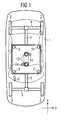
- FIG. 1 shows a schematic plan view of a motor vehicle test stand with a motor vehicle 1 to be tested on it.
- the motor vehicle test stand shown has an upper frame unit 6, on which extending in the vehicle longitudinal direction support arms 5 are attached. These are connected in their end regions extending in the vehicle transverse direction support arms 3,4. On the outer sides of the support arms 3,4 Radability electrode 2 are provided.
- the upper frame unit 6 is formed in the form of a metal plate and has a square or rectangular base. In the region of the corners of the upper frame unit 6, the tilting device, as will be explained in more detail below with reference to Figures 2 and 3, each equipped with a lifting unit.
- a motor vehicle test bench which preferably is an ESP test bench (E lektronisches- S tabilticians- P rogram), with guides 12 and an excavating unit 11 is provided, leading to a lifting of the vehicle in the test position serve.
- ESP test bench E lektronisches- S tabilticians- P rogram
- the vehicle can be tilted both longitudinally and transversely as part of the ESP testing process.
- Figure 2 shows a sketch of a part of a motor vehicle test stand according to the invention, from which emerge the essential features of the invention.
- the illustrated part is a side view of the front right corner of the test stand in the direction of the arrow p in Figure 1.
- FIG. 2 shows that below the upper frame unit 6, a lower frame unit 13 is provided.
- the lower frame unit 13 has a square or rectangular base.
- the two frame units are arranged approximately congruently one above the other. Consequently, one of the lifting units is also provided in the region of the four corners of the lower frame unit 13.
- the two frame units 6 and 13 are connected to each other exclusively via these four lifting units.
- the lifting unit 17 shown in FIG. 2 is provided with a piston rod 15 on its upper side. This is by a widening upward conical hole of the lower Guided frame unit 13 and connected to the upper frame unit 6 via a spherical bearing 14.
- a cone-shaped frame 16 of the piston rod 15 is inserted into the cone-shaped hole of the lower frame unit 13 such that this hole is closed.
- the conical frame 16 of the piston rod is preferably fixedly connected to the piston rod, for example, welded to this. Characterized a positive connection between the piston rod and the lower frame unit is ensured in the plane of the lower frame unit in the x- / y-direction and formed a fixed bearing between the lower and upper frame unit.
- the piston rod 15 presses the upper frame unit 6 in the region of the right front corner 8 of the tilting device upwards. Since in this extension of the piston rod 15 and the cone-shaped frame 16 is moved upward, created in the conical hole of the lower frame unit 13, a lateral clearance through which a slight lateral deflection is allowed for the piston rod during extension.
- the piston rod 15 arranged in the left front corner 7 of the tilting device is extended by the lifting unit at the same time as the piston rod 15 arranged in the right front corner 8 of the tilting device and remain in the rear corners 9 and 10 located piston rods in the retracted state, then there is a tilting of the vehicle about its transverse axis.
- the lifting units arranged in the corners are preferably operable in both the compression and in the pulling direction in order to ensure a secured position in all operating states.
- FIG. 3 shows the detail B of the motor vehicle test stand shown in FIG. 2 in an enlarged view.
- this enlarged view in particular, the connection of the piston rod 15 via a spherical bearing 14 with the upper frame unit 6 and the closing of the cone-shaped hole in the lower frame unit 13 by the cone-shaped frame 16 of the piston rod 15 are shown.
- the control of the extension of the lifting units associated piston rods is effected by a corresponding control of the lifting units by a central control unit.
- Each of these tilting operations is characterized in that two adjacent piston rods are extended by the associated lifting unit, while the other two remain in the retracted state.
- the said four lifting units which serve to extend the respective piston rod and thus to carry out the tilting operations, are provided exclusively for carrying out these tilting operations.
Landscapes
- Life Sciences & Earth Sciences (AREA)
- Engineering & Computer Science (AREA)
- Geology (AREA)
- Mechanical Engineering (AREA)
- Structural Engineering (AREA)
- Physics & Mathematics (AREA)
- General Physics & Mathematics (AREA)
- Investigating Strength Of Materials By Application Of Mechanical Stress (AREA)
- Vehicle Cleaning, Maintenance, Repair, Refitting, And Outriggers (AREA)
- Testing Of Engines (AREA)
- Polymerization Catalysts (AREA)
Claims (8)
- Banc d'essai pour véhicules automobiles équipé d'un dispositif d'inclinaison qui comporte une unité inférieure de cadre (13) et une unité supérieure de cadre (6) qui peut s'incliner par rapport à celle-ci, le dispositif d'inclinaison étant en outre équipé de quatre unités de levage (17) placées dans la zone des coins (7, 8, 9, 10) des unités de cadre,
caractérisé en ce que dans la zone de ses quatre coins l'unité de cadre inférieure (13) comporte respectivement un trou conique qui s'élargit vers le haut et dans lequel est guidée une tige de piston (15) qui fait partie d'une unité de levage (17) respectivement correspondante. - Banc d'essai pour véhicules automobiles selon la revendication 1, caractérisé en ce que les unités de cadre inférieure et supérieure sont reliées l'une à l'autre exclusivement par les unités de levage.
- Banc d'essai pour véhicules automobiles selon la revendication 1 ou 2, caractérisé en ce que sur son pourtour extérieur la tige de piston (15) est munie d'un encadrement (16) conique qui s'élargit vers le haut et qui à l'état rentré forme entre la tige de piston et l'unité de cadre inférieure (13) une liaison centrée par combinaison de formes en direction x / y, grâce à quoi on obtient un palier fixe entre les unités de cadre inférieure et supérieure.
- Banc d'essai pour véhicules automobiles selon l'une des revendications précédentes, caractérisé en ce que, à son extrémité supérieure, la tige de piston (15) est reliée à l'unité de cadre supérieure (6) par l'intermédiaire d'un palier (14) sphérique.
- Banc d'essai pour véhicules automobiles selon l'une des revendications précédentes, caractérisé en ce que, quand l'unité de cadre supérieure (6) s'incline, deux tiges de piston voisines restent en état rentré et les deux autres se déploient.
- Banc d'essai pour véhicules automobiles selon l'une des revendications précédentes, caractérisé en ce qu'une tige de piston est soumise à une légère déviation latérale lors du déploiement.
- Banc d'essai pour véhicules automobiles selon l'une des revendications précédentes, caractérisé en ce que les quatre unités de levage (17) sont exclusivement prévues pour incliner l'unité de cadre supérieure (6).
- Banc d'essai pour véhicules automobiles selon l'une des revendications précédentes, caractérisé en ce qu'il comporte une unité centrale de pilotage reliée à une unité de commande et destinée à commander les unités de levage.
Applications Claiming Priority (3)
| Application Number | Priority Date | Filing Date | Title |
|---|---|---|---|
| DE20103107U DE20103107U1 (de) | 2001-02-21 | 2001-02-21 | Kraftfahrzeug-Prüfstand mit einer Kippvorrichtung |
| DE20103107U | 2001-02-21 | ||
| PCT/DE2002/000614 WO2002066362A2 (fr) | 2001-02-21 | 2002-02-20 | Banc d'essai d'automobile dote d'un dispositif d'inclinaison |
Publications (2)
| Publication Number | Publication Date |
|---|---|
| EP1362002A2 EP1362002A2 (fr) | 2003-11-19 |
| EP1362002B1 true EP1362002B1 (fr) | 2007-10-10 |
Family
ID=7953343
Family Applications (1)
| Application Number | Title | Priority Date | Filing Date |
|---|---|---|---|
| EP02712796A Expired - Lifetime EP1362002B1 (fr) | 2001-02-21 | 2002-02-20 | Banc d'essai d'automobile dote d'un dispositif d'inclinaison |
Country Status (5)
| Country | Link |
|---|---|
| US (1) | US7316158B2 (fr) |
| EP (1) | EP1362002B1 (fr) |
| DE (2) | DE20103107U1 (fr) |
| ES (1) | ES2291453T3 (fr) |
| WO (1) | WO2002066362A2 (fr) |
Cited By (1)
| Publication number | Priority date | Publication date | Assignee | Title |
|---|---|---|---|---|
| DE102015104890A1 (de) | 2015-03-30 | 2016-10-06 | Gpi Gesellschaft Für Prüfstanduntersuchungen Und Ingenieurdienstleistungen Mbh | Testsystem und Testverfahren zum Test einer fahrzeug- und/oder fahrzeugführerspezifischen Signalwahrnehmung und -reaktion sowie Konfigurationssystem und Konfigurationsverfahren zur fahrzeug- und/oder fahrzeugführerspezifischen Konfiguration wenigstens einer Fahrzeugführer-System-Schnittstelle |
Families Citing this family (7)
| Publication number | Priority date | Publication date | Assignee | Title |
|---|---|---|---|---|
| US7461556B2 (en) * | 2005-11-03 | 2008-12-09 | Chip Ganassi Racing Teams, Inc. | Test system for dynamically analyzing a vehicle under simulated road conditions |
| US20110153298A1 (en) * | 2009-12-23 | 2011-06-23 | Stein Douglas J | Vehicle rollover simulation |
| DE102010034850B4 (de) * | 2010-05-19 | 2015-01-22 | Fraunhofer-Gesellschaft zur Förderung der angewandten Forschung e.V. | Straßensimulationsprüfstand |
| US8943871B2 (en) | 2011-09-13 | 2015-02-03 | Seattle Safety Llc | Crash test method and apparatus including pitch simulation |
| CA2810606A1 (fr) * | 2012-04-10 | 2013-10-10 | CAA South Central Ontario | Methode et trousse pour l'offre d'une formation sur l'operation d'un dispositif de remorquage |
| CN112055809B (zh) * | 2018-05-10 | 2023-08-04 | 东洋电机制造株式会社 | 底盘测功装置 |
| DE102018127572B4 (de) * | 2018-11-05 | 2020-06-10 | Horiba Europe Gmbh | Schwenkrahmen für einen Prüfstand für einen Antriebsstrang |
Family Cites Families (23)
| Publication number | Priority date | Publication date | Assignee | Title |
|---|---|---|---|---|
| US1525447A (en) * | 1923-11-30 | 1925-02-10 | Charles M Hose | Apparatus for elevating automobiles |
| US1994942A (en) * | 1932-10-18 | 1935-03-19 | Claude C Calkins | Vehicle rocking machine |
| US2274619A (en) * | 1938-04-22 | 1942-02-24 | Arthur A Johnson | Vehicle rocking device |
| US2471901A (en) * | 1945-04-25 | 1949-05-31 | Weaver Mfg Co | Load-lifting appliance |
| US2929519A (en) * | 1956-11-27 | 1960-03-22 | Northrop Corp | Elevating trailer |
| US3655081A (en) * | 1970-02-06 | 1972-04-11 | John Thomas Monk | Straddle carriers |
| US3827289A (en) * | 1972-12-05 | 1974-08-06 | Us Army | Vehicle test fixture |
| SE377497B (fr) * | 1973-01-17 | 1975-07-07 | R P S Graham | |
| US4263809A (en) * | 1979-07-02 | 1981-04-28 | Mts Systems Corporation | Tetraxial vehicle test fixture |
| GB2084541B (en) * | 1980-10-01 | 1984-08-30 | Fawdry John Anthony | Self-levelling vehicle support arrangement |
| DE3218019C1 (de) * | 1982-05-13 | 1983-12-22 | Fraunhofer-Gesellschaft zur Förderung der angewandten Forschung e.V., 8000 München | Anordnung zur Simulation der Betriebsbeanspruchungen von Fahrzeugen bzw. Fahrzeugbaugruppen |
| US4796029A (en) * | 1986-04-14 | 1989-01-03 | Fmc Corporation | Turn tilt table |
| US5040637A (en) * | 1990-02-16 | 1991-08-20 | Vbm Corporation | Lift assembly |
| US5213458A (en) * | 1990-07-27 | 1993-05-25 | Sea-Land Corporation, Inc. | Method and apparatus for containerized shipment of automobiles |
| US5074000A (en) * | 1991-01-11 | 1991-12-24 | Ssi Medical Services, Inc. | Apparatus for performing head and foot Trendelenburg therapy |
| US5344266A (en) * | 1993-04-16 | 1994-09-06 | Kolb Peter W | Fully adjustable storage device for loading and transporting vehicles in containers |
| US5890855A (en) * | 1994-04-15 | 1999-04-06 | Claps; William R. | Method and apparatus for transporting cars |
| US5597359A (en) * | 1995-10-26 | 1997-01-28 | Doron Precision Systems, Inc. | Audience motion platform |
| JPH09126953A (ja) * | 1995-11-01 | 1997-05-16 | Bridgestone Corp | 平板循環装置及び力測定装置 |
| CZ20013491A3 (cs) * | 1999-03-31 | 2002-05-15 | Siemens Aktiengesellschaft | Dynamické zkuąební zařízení pro vozidlo, zkuąebna a výrobní linka s dynamickým zkuąebním zařízením a jejich vyuľití pro přezkuąování bezpečnostního systému příčné stability ve vozidle |
| DE10022534A1 (de) * | 2000-05-09 | 2001-11-15 | Snap On Deutschland Holding | Fahrwerks-Meßvorrichtung und Verfahren zum Vermessen eines Fahrwerks |
| US6422536B1 (en) * | 2000-07-12 | 2002-07-23 | Force Control Industries, Inc. | Lifter apparatus for raising and lowering a part |
| WO2003093781A2 (fr) * | 2002-05-03 | 2003-11-13 | Burke E Porter Machinery Company | Procede de mesure de la propension d'un vehicule a faire un tonneau |
-
2001
- 2001-02-21 DE DE20103107U patent/DE20103107U1/de not_active Expired - Lifetime
-
2002
- 2002-02-20 EP EP02712796A patent/EP1362002B1/fr not_active Expired - Lifetime
- 2002-02-20 ES ES02712796T patent/ES2291453T3/es not_active Expired - Lifetime
- 2002-02-20 WO PCT/DE2002/000614 patent/WO2002066362A2/fr not_active Ceased
- 2002-02-20 DE DE50211042T patent/DE50211042D1/de not_active Expired - Lifetime
-
2003
- 2003-08-21 US US10/644,907 patent/US7316158B2/en not_active Expired - Fee Related
Cited By (2)
| Publication number | Priority date | Publication date | Assignee | Title |
|---|---|---|---|---|
| DE102015104890A1 (de) | 2015-03-30 | 2016-10-06 | Gpi Gesellschaft Für Prüfstanduntersuchungen Und Ingenieurdienstleistungen Mbh | Testsystem und Testverfahren zum Test einer fahrzeug- und/oder fahrzeugführerspezifischen Signalwahrnehmung und -reaktion sowie Konfigurationssystem und Konfigurationsverfahren zur fahrzeug- und/oder fahrzeugführerspezifischen Konfiguration wenigstens einer Fahrzeugführer-System-Schnittstelle |
| EP3101404A2 (fr) | 2015-03-30 | 2016-12-07 | GPI Gesellschaft Für Prüfstanduntersuchungen und Ingenieurdienstleistungen MbH | Systeme d'essai et procede d'essai et systeme de configuration et procede de configuration destine a configurer au moins une interface systeme-conducteur de vehicule |
Also Published As
| Publication number | Publication date |
|---|---|
| DE20103107U1 (de) | 2002-04-04 |
| ES2291453T3 (es) | 2008-03-01 |
| WO2002066362A2 (fr) | 2002-08-29 |
| US20040060350A1 (en) | 2004-04-01 |
| DE50211042D1 (de) | 2007-11-22 |
| EP1362002A2 (fr) | 2003-11-19 |
| WO2002066362A3 (fr) | 2002-11-21 |
| US7316158B2 (en) | 2008-01-08 |
Similar Documents
| Publication | Publication Date | Title |
|---|---|---|
| DE69517176T2 (de) | Verfahren und vorrichtung zum übertragen von ladeeinheiten zwischen zwei trägern | |
| DE602004000685T2 (de) | Aufhängung eines Triebwerks unter einer Flugzeugtragfläche | |
| EP0819039A1 (fr) | Plate-forme elevatrice hydraulique, notamment plate-forme elevatrice pour motos | |
| EP2090462B1 (fr) | Châssis de conteneur réglable en longueur | |
| EP1903147A2 (fr) | Chargeur frontal doté d'un guidage parallèle mécanique | |
| EP1362002B1 (fr) | Banc d'essai d'automobile dote d'un dispositif d'inclinaison | |
| DE2545863A1 (de) | Vorrichtung zur handhabung eines transportbehaelterns | |
| WO1996011874A1 (fr) | Dispositif elevateur et rotatif pour enlever un vehicule a moteur | |
| EP1770050B1 (fr) | Grue repliable | |
| DE102019206185A1 (de) | Lenksäulenvorrichtung für fahrzeuge | |
| EP1719661B1 (fr) | Plate-forme de hayon et procédé pour faire sortir et rentrer la même | |
| EP1123857B1 (fr) | Fixation de roue de secours | |
| DE102004033886B4 (de) | Halteanordnung für Container | |
| EP1231105A2 (fr) | Mécanisme de levage et de descente, notamment pour un véhicule de transport de voitures | |
| DE2430033B2 (de) | Spindelwagenheber | |
| DE3934121A1 (de) | Gekroepfte zuggabel fuer mehrachsige, drehschemelgelenkte anhaengerfahrzeuge | |
| EP4190634B1 (fr) | Dispositif de maintien d'une extrémité d'un objet allongé, en particulier d'une charge autoportante, et véhicule utilisant ce dispositif | |
| EP0903266B1 (fr) | Protection anti-encastrement variable | |
| DE602004010476T2 (de) | Rahmen für einen Arbeitsplatz für den Zusammenbau eines Stossfängers, und Arbeitsplatz für den Zusammenbau von Stossfängern | |
| DE19810664B4 (de) | Radaufhängung | |
| EP0184667B1 (fr) | Camion à cabine basculante | |
| EP0795451A2 (fr) | Dispositif de levage pour un plateau de base posé horizontalement | |
| DE2444082B2 (de) | Dreiseitenkippfahrzeug | |
| DE10153164C2 (de) | Wagenheber mit einem Tragarm und Verfahren zum Herstellen des Tragarms | |
| DE102019006750A1 (de) | Aufnahmevorrichtung zum horizontalen Transport und Montagevorbereitung von Hinterachsen von Fahrzeugen |
Legal Events
| Date | Code | Title | Description |
|---|---|---|---|
| PUAI | Public reference made under article 153(3) epc to a published international application that has entered the european phase |
Free format text: ORIGINAL CODE: 0009012 |
|
| AK | Designated contracting states |
Kind code of ref document: A2 Designated state(s): AT BE CH CY DE DK ES FI FR GB GR IE IT LI LU MC NL PT SE TR |
|
| 17P | Request for examination filed |
Effective date: 20030228 |
|
| 17Q | First examination report despatched |
Effective date: 20061025 |
|
| GRAP | Despatch of communication of intention to grant a patent |
Free format text: ORIGINAL CODE: EPIDOSNIGR1 |
|
| GRAS | Grant fee paid |
Free format text: ORIGINAL CODE: EPIDOSNIGR3 |
|
| GRAA | (expected) grant |
Free format text: ORIGINAL CODE: 0009210 |
|
| AK | Designated contracting states |
Kind code of ref document: B1 Designated state(s): DE ES FR |
|
| REF | Corresponds to: |
Ref document number: 50211042 Country of ref document: DE Date of ref document: 20071122 Kind code of ref document: P |
|
| ET | Fr: translation filed | ||
| REG | Reference to a national code |
Ref country code: ES Ref legal event code: FG2A Ref document number: 2291453 Country of ref document: ES Kind code of ref document: T3 |
|
| PLBE | No opposition filed within time limit |
Free format text: ORIGINAL CODE: 0009261 |
|
| STAA | Information on the status of an ep patent application or granted ep patent |
Free format text: STATUS: NO OPPOSITION FILED WITHIN TIME LIMIT |
|
| 26N | No opposition filed |
Effective date: 20080711 |
|
| PGFP | Annual fee paid to national office [announced via postgrant information from national office to epo] |
Ref country code: FR Payment date: 20110224 Year of fee payment: 10 |
|
| PGFP | Annual fee paid to national office [announced via postgrant information from national office to epo] |
Ref country code: ES Payment date: 20110311 Year of fee payment: 10 |
|
| REG | Reference to a national code |
Ref country code: FR Ref legal event code: ST Effective date: 20121031 |
|
| PG25 | Lapsed in a contracting state [announced via postgrant information from national office to epo] |
Ref country code: FR Free format text: LAPSE BECAUSE OF NON-PAYMENT OF DUE FEES Effective date: 20120229 |
|
| REG | Reference to a national code |
Ref country code: ES Ref legal event code: FD2A Effective date: 20130709 |
|
| PG25 | Lapsed in a contracting state [announced via postgrant information from national office to epo] |
Ref country code: ES Free format text: LAPSE BECAUSE OF NON-PAYMENT OF DUE FEES Effective date: 20120221 |
|
| PGFP | Annual fee paid to national office [announced via postgrant information from national office to epo] |
Ref country code: DE Payment date: 20140417 Year of fee payment: 13 |
|
| REG | Reference to a national code |
Ref country code: DE Ref legal event code: R119 Ref document number: 50211042 Country of ref document: DE |
|
| PG25 | Lapsed in a contracting state [announced via postgrant information from national office to epo] |
Ref country code: DE Free format text: LAPSE BECAUSE OF NON-PAYMENT OF DUE FEES Effective date: 20150901 |