EP1362002B1 - Test stand with tipping device for motor vehicles - Google Patents
Test stand with tipping device for motor vehicles Download PDFInfo
- Publication number
- EP1362002B1 EP1362002B1 EP02712796A EP02712796A EP1362002B1 EP 1362002 B1 EP1362002 B1 EP 1362002B1 EP 02712796 A EP02712796 A EP 02712796A EP 02712796 A EP02712796 A EP 02712796A EP 1362002 B1 EP1362002 B1 EP 1362002B1
- Authority
- EP
- European Patent Office
- Prior art keywords
- test stand
- motor vehicles
- frame unit
- piston rod
- unit
- Prior art date
- Legal status (The legal status is an assumption and is not a legal conclusion. Google has not performed a legal analysis and makes no representation as to the accuracy of the status listed.)
- Expired - Lifetime
Links
- 238000012360 testing method Methods 0.000 title claims description 31
- 239000007787 solid Substances 0.000 claims 1
- 238000000034 method Methods 0.000 description 3
- 238000009412 basement excavation Methods 0.000 description 1
- 230000006835 compression Effects 0.000 description 1
- 238000007906 compression Methods 0.000 description 1
- 230000001419 dependent effect Effects 0.000 description 1
- 238000012423 maintenance Methods 0.000 description 1
- 239000002184 metal Substances 0.000 description 1
- 238000012986 modification Methods 0.000 description 1
- 230000004048 modification Effects 0.000 description 1
- 238000004904 shortening Methods 0.000 description 1
- 238000010998 test method Methods 0.000 description 1
Images

Classifications
-
- G—PHYSICS
- G01—MEASURING; TESTING
- G01M—TESTING STATIC OR DYNAMIC BALANCE OF MACHINES OR STRUCTURES; TESTING OF STRUCTURES OR APPARATUS, NOT OTHERWISE PROVIDED FOR
- G01M17/00—Testing of vehicles
- G01M17/007—Wheeled or endless-tracked vehicles
-
- B—PERFORMING OPERATIONS; TRANSPORTING
- B66—HOISTING; LIFTING; HAULING
- B66F—HOISTING, LIFTING, HAULING OR PUSHING, NOT OTHERWISE PROVIDED FOR, e.g. DEVICES WHICH APPLY A LIFTING OR PUSHING FORCE DIRECTLY TO THE SURFACE OF A LOAD
- B66F7/00—Lifting frames, e.g. for lifting vehicles; Platform lifts
- B66F7/10—Lifting frames, e.g. for lifting vehicles; Platform lifts with platforms supported directly by jacks
- B66F7/16—Lifting frames, e.g. for lifting vehicles; Platform lifts with platforms supported directly by jacks by one or more hydraulic or pneumatic jacks
-
- B—PERFORMING OPERATIONS; TRANSPORTING
- B66—HOISTING; LIFTING; HAULING
- B66F—HOISTING, LIFTING, HAULING OR PUSHING, NOT OTHERWISE PROVIDED FOR, e.g. DEVICES WHICH APPLY A LIFTING OR PUSHING FORCE DIRECTLY TO THE SURFACE OF A LOAD
- B66F7/00—Lifting frames, e.g. for lifting vehicles; Platform lifts
- B66F7/22—Lifting frames, e.g. for lifting vehicles; Platform lifts with tiltable platforms
Definitions
- the invention relates to a motor vehicle test stand having a tilting device. This is used as part of an ESP test procedure for tilting the respective motor vehicle to be tested about its longitudinal and transverse axes.
- the US 1,525,447 A which corresponds to the preamble of claim 1, discloses a motor vehicle test stand with a tilting device, which has a lower frame unit and a relative to this tiltable upper frame unit.
- the present invention seeks to provide a motor vehicle test stand with a tilting device, in which the time required for a change in the tilting direction is reduced, so that the number of testable vehicles per unit time is increased.
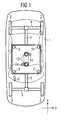
- FIG. 1 shows a schematic plan view of a motor vehicle test stand with a motor vehicle 1 to be tested on it.
- the motor vehicle test stand shown has an upper frame unit 6, on which extending in the vehicle longitudinal direction support arms 5 are attached. These are connected in their end regions extending in the vehicle transverse direction support arms 3,4. On the outer sides of the support arms 3,4 Radability electrode 2 are provided.
- the upper frame unit 6 is formed in the form of a metal plate and has a square or rectangular base. In the region of the corners of the upper frame unit 6, the tilting device, as will be explained in more detail below with reference to Figures 2 and 3, each equipped with a lifting unit.
- a motor vehicle test bench which preferably is an ESP test bench (E lektronisches- S tabilticians- P rogram), with guides 12 and an excavating unit 11 is provided, leading to a lifting of the vehicle in the test position serve.
- ESP test bench E lektronisches- S tabilticians- P rogram
- the vehicle can be tilted both longitudinally and transversely as part of the ESP testing process.
- Figure 2 shows a sketch of a part of a motor vehicle test stand according to the invention, from which emerge the essential features of the invention.
- the illustrated part is a side view of the front right corner of the test stand in the direction of the arrow p in Figure 1.
- FIG. 2 shows that below the upper frame unit 6, a lower frame unit 13 is provided.
- the lower frame unit 13 has a square or rectangular base.
- the two frame units are arranged approximately congruently one above the other. Consequently, one of the lifting units is also provided in the region of the four corners of the lower frame unit 13.
- the two frame units 6 and 13 are connected to each other exclusively via these four lifting units.
- the lifting unit 17 shown in FIG. 2 is provided with a piston rod 15 on its upper side. This is by a widening upward conical hole of the lower Guided frame unit 13 and connected to the upper frame unit 6 via a spherical bearing 14.
- a cone-shaped frame 16 of the piston rod 15 is inserted into the cone-shaped hole of the lower frame unit 13 such that this hole is closed.
- the conical frame 16 of the piston rod is preferably fixedly connected to the piston rod, for example, welded to this. Characterized a positive connection between the piston rod and the lower frame unit is ensured in the plane of the lower frame unit in the x- / y-direction and formed a fixed bearing between the lower and upper frame unit.
- the piston rod 15 presses the upper frame unit 6 in the region of the right front corner 8 of the tilting device upwards. Since in this extension of the piston rod 15 and the cone-shaped frame 16 is moved upward, created in the conical hole of the lower frame unit 13, a lateral clearance through which a slight lateral deflection is allowed for the piston rod during extension.
- the piston rod 15 arranged in the left front corner 7 of the tilting device is extended by the lifting unit at the same time as the piston rod 15 arranged in the right front corner 8 of the tilting device and remain in the rear corners 9 and 10 located piston rods in the retracted state, then there is a tilting of the vehicle about its transverse axis.
- the lifting units arranged in the corners are preferably operable in both the compression and in the pulling direction in order to ensure a secured position in all operating states.
- FIG. 3 shows the detail B of the motor vehicle test stand shown in FIG. 2 in an enlarged view.
- this enlarged view in particular, the connection of the piston rod 15 via a spherical bearing 14 with the upper frame unit 6 and the closing of the cone-shaped hole in the lower frame unit 13 by the cone-shaped frame 16 of the piston rod 15 are shown.
- the control of the extension of the lifting units associated piston rods is effected by a corresponding control of the lifting units by a central control unit.
- Each of these tilting operations is characterized in that two adjacent piston rods are extended by the associated lifting unit, while the other two remain in the retracted state.
- the said four lifting units which serve to extend the respective piston rod and thus to carry out the tilting operations, are provided exclusively for carrying out these tilting operations.
Landscapes
- Life Sciences & Earth Sciences (AREA)
- Engineering & Computer Science (AREA)
- Geology (AREA)
- Mechanical Engineering (AREA)
- Structural Engineering (AREA)
- Physics & Mathematics (AREA)
- General Physics & Mathematics (AREA)
- Investigating Strength Of Materials By Application Of Mechanical Stress (AREA)
- Vehicle Cleaning, Maintenance, Repair, Refitting, And Outriggers (AREA)
- Testing Of Engines (AREA)
- Polymerization Catalysts (AREA)
Description
Die Erfindung betrifft einen Kraftfahrzeug-Prüfstand, welcher eine Kippvorrichtung aufweist. Diese wird im Rahmen eines ESP-Prüfungsvorganges zu einem Kippen des jeweils zu prüfenden Kraftfahrzeugs um dessen Längs- und Querachse verwendet.The invention relates to a motor vehicle test stand having a tilting device. This is used as part of an ESP test procedure for tilting the respective motor vehicle to be tested about its longitudinal and transverse axes.
Die
Aus der
Nachteilig bei einer derartigen Vorgehensweise ist, dass die zu einer Veränderung der Kipprichtung erforderlichen Zeiten wegen der Notwendigkeit des Verstellens der Verschlussmittel vergleichsweise lang sind.The disadvantage of such a procedure is that the times required for a change in the tilting direction are comparatively long because of the necessity of adjusting the closure means.
Ausgehend von diesem Stand der Technik liegt der Erfindung die Aufgabe zugrunde, einen Kraftfahrzeug-Prüfstand mit einer Kippvorrichtung anzugeben, bei welchem die für eine Veränderung der Kipprichtung benötigte Zeit verringert ist, so dass die Anzahl der pro Zeiteinheit prüfbaren Fahrzeuge erhöht ist.Based on this prior art, the present invention seeks to provide a motor vehicle test stand with a tilting device, in which the time required for a change in the tilting direction is reduced, so that the number of testable vehicles per unit time is increased.
Diese Aufgabe wird durch einen Kraftfahrzeug-Prüfstand mit den im Anspruch 1 angegebenen Merkmalen gelöst.This object is achieved by a motor vehicle test stand having the features specified in claim 1.
Vorteilhafte Ausgestaltungen und Weiterbildungen der Erfindung ergeben sich aus den abhängigen Ansprüchen.Advantageous embodiments and modifications of the invention will become apparent from the dependent claims.
Die Vorteile der Erfindung bestehen insbesondere in einer Verkürzung der Taktzeiten, da die Umrüstzeiten wesentlich niedriger sind als beim bekannten Stand der Technik. Darüber hinaus ist bei einer Verwendung eines Kraftfahrzeug-Prüfstandes gemäß der Erfindung die Prozess-Sicherheit erhöht und der Wartungsaufwand im Vergleich zu bekannten Kraftfahrzeugprüfständen verringert.The advantages of the invention consist in particular in a shortening of the cycle times, since the changeover times are substantially lower than in the known prior art. In addition, when using a motor vehicle test stand according to the invention, the process safety increases and reduces the maintenance effort compared to known motor vehicle test stands.
Weitere vorteilhafte Eigenschaften der Erfindung ergeben sich aus der nachfolgenden Beschreibung anhand eines Ausführungsbeispiels.Further advantageous features of the invention will become apparent from the following description with reference to an embodiment.
Es zeigt:
- FIG 1
- eine schematische Draufsicht eines Kraftfahrzeug-Prüfstandes mit einem darauf angeordneten, zu prüfenden Kraftfahrzeug;
- FIG 2
- eine Skizze eines Teils eines Kraftfahrzeug-Prüfstands gemäß der Erfindung, aus der die wesentlichen Merkmale des beanspruchten Kraftfahrzeug-Prüfstandes ersichtlich sind, und
- FIG 3
- die Einzelheit B des in
Figur 2 gezeigten Kraftfahrzeug-Prüfstandes in vergrößerter Darstellung.
- FIG. 1
- a schematic plan view of a motor vehicle test stand with arranged thereon, to be tested motor vehicle;
- FIG. 2
- a sketch of a portion of a motor vehicle test stand according to the invention, from which the essential features of the claimed motor vehicle test stand can be seen, and
- FIG. 3
- the detail B of the motor vehicle test stand shown in Figure 2 in an enlarged view.
Die Figur 1 zeigt eine schematische Draufsicht eines Kraftfahrzeug-Prüfstandes mit einem darauf angeordneten zu prüfenden Kraftfahrzeug 1.FIG. 1 shows a schematic plan view of a motor vehicle test stand with a motor vehicle 1 to be tested on it.
Der gezeigte Kraftfahrzeug-Prüfstand weist eine obere Rahmeneinheit 6 auf, an welcher in Fahrzeuglängsrichtung verlaufende Tragarme 5 befestigt sind. Diese sind in ihren Endbereichen mit in Fahrzeugquerrichtung verlaufenden Tragarmen 3,4 verbunden. An den Außenseiten der Tragarme 3,4 sind Radaufnahmeelemente 2 vorgesehen.The motor vehicle test stand shown has an
Die obere Rahmeneinheit 6 ist eben in Form einer Metallplatte ausgebildet und hat eine quadratische oder rechteckförmige Grundfläche. Im Bereich der Ecken der oberen Rahmeneinheit 6 ist die Kippvorrichtung, wie noch unten anhand der Figuren 2 und 3 näher erläutert wird, jeweils mit einer Hubeinheit ausgestattet.The
Weiterhin ist ein Kraftfahrzeug-Prüfstand gemäß der Erfindung, bei dem es sich vorzugsweise um einen ESP-Prüfstand handelt (Elektronisches-Stabilitäts-Programm), mit Führungen 12 und einer Aushubeinheit 11 versehen, die zu einem Anheben des Fahrzeugs in die Prüfposition dienen.Further, a motor vehicle test bench according to the invention, which preferably is an ESP test bench (E lektronisches- S tabilitäts- P rogram), with
Mittels der Kippvorrichtung kann im Rahmen des ESP-Prüfvorganges ein Verkippen des Fahrzeugs sowohl in Längs- als auch in Querrichtung erfolgen.By means of the tilting device, the vehicle can be tilted both longitudinally and transversely as part of the ESP testing process.
Die Figur 2 zeigt eine Skizze eines Teils eines Kraftfahrzeug-Prüfstandes gemäß der Erfindung, aus der die wesentlichen Merkmale der Erfindung hervorgehen. Bei dem dargestellten Teil handelt es sich um eine Seitenansicht der vorderen rechte Ecke des Prüfstandes in Richtung des Pfeiles p in Figur 1.Figure 2 shows a sketch of a part of a motor vehicle test stand according to the invention, from which emerge the essential features of the invention. In the illustrated part is a side view of the front right corner of the test stand in the direction of the arrow p in Figure 1.
Aus der Figur 2 geht hervor, dass unterhalb der oberen Rahmeneinheit 6 eine untere Rahmeneinheit 13 vorgesehen ist. Auch die untere Rahmeneinheit 13 hat eine quadratische oder rechteckförmige Grundfläche. Die beiden Rahmeneinheiten sind etwa deckungsgleich übereinander angeordnet. Folglich ist auch im Bereich der vier Ecken der unteren Rahmeneinheit 13 jeweils eine der Hubeinheiten vorgesehen. Die beiden Rahmeneinheiten 6 und 13 sind ausschließlich über diese vier Hubeinheiten miteinander verbunden.From Figure 2 shows that below the
Die in der Figur 2 dargestellte Hubeinheit 17 ist an ihrer Oberseite mit einer Kolbenstange 15 versehen. Diese ist durch ein sich nach oben verbreiterndes konusförmiges Loch der unteren Rahmeneinheit 13 geführt und mit der oberen Rahmeneinheit 6 über ein sphärisches Lager 14 verbunden.The
Im nicht ausgefahrenen Zustand der Kolbenstange 15, welcher in der Figur 2 gezeigt ist, ist eine konusförmige Umrahmung 16 der Kolbenstange 15 derart in das konusförmige Loch der unteren Rahmeneinheit 13 eingesetzt, dass dieses Loch verschlossen ist. Die konusförmige Umrahmung 16 der Kolbenstange ist vorzugsweise mit der Kolbenstange fest verbunden, beispielsweise auf diese aufgeschweißt. Dadurch wird in der Ebene der unteren Rahmeneinheit in x-/y-Richtung ein Formschluss zwischen der Kolbenstange und der unteren Rahmeneinheit sichergestellt und ein Festlager zwischen unterer und oberer Rahmeneinheit gebildet.In the non-extended state of the
Wird die Kolbenstange 15 durch die Hubeinheit 17 ausgefahren, dann drückt die Kolbenstange 15 die obere Rahmeneinheit 6 im Bereich der rechten vorderen Ecke 8 der Kippvorrichtung nach oben. Da bei diesem Ausfahren der Kolbenstange 15 auch die konusförmige Umrahmung 16 nach oben bewegt wird, entsteht im konusförmigen Loch der unteren Rahmeneinheit 13 ein seitlicher Freiraum, durch welchen für die Kolbenstange beim Ausfahren eine geringfügige seitliche Auslenkung zugelassen wird.If the
Wird gleichzeitig mit der in der rechten vorderen Ecke 8 der Kippvorrichtung angeordneten Kolbenstange 15 auch die in der rechten hinteren Ecke 9 der Kippvorrichtung angeordnete Kolbenstange durch die dortige Hubeinheit ausgefahren und verbleiben die in den Ecken 7 und 10 befindlichen Kolbenstangen im eingefahrenen Zustand, dann erfolgt ein Verkippen des Fahrzeugs um seine Längsachse.Is at the same time arranged in the right
Wird hingegen gleichzeitig mit der in der rechten vorderen Ecke 8 der Kippvorrichtung angeordnete Kolbenstange 15 auch die in der linken vorderen Ecke 7 der Kippvorrichtung angeordnete Kolbenstange durch die dortige Hubeinheit ausgefahren und verbleiben die in den hinteren Ecken 9 und 10 befindlichen Kolbenstangen im eingefahrenen Zustand, dann erfolgt ein Verkippen des Fahrzeugs um seine Querachse.If, on the other hand, the
Die in den Ecken angeordneten Hubeinheiten sind vorzugsweise sowohl in Druck- als auch in Zugrichtung betreibbar, um in allen Betriebszuständen eine gesicherte Position zu gewährleisten.The lifting units arranged in the corners are preferably operable in both the compression and in the pulling direction in order to ensure a secured position in all operating states.
Die Figur 3 zeigt die Einzelheit B des in der Figur 2 gezeigten Kraftfahrzeug-Prüfstandes in vergrößerter Darstellung. In dieser vergrößerten Darstellung sind insbesondere die Verbindung der Kolbenstange 15 über ein sphärisches Lager 14 mit der oberen Rahmeneinheit 6 und das Verschließen des konusförmigen Loches in der unteren Rahmeneinheit 13 durch die konusförmige Umrahmung 16 der Kolbenstange 15 gezeigt.FIG. 3 shows the detail B of the motor vehicle test stand shown in FIG. 2 in an enlarged view. In this enlarged view, in particular, the connection of the
Die Steuerung des Ausfahrens der den Hubeinheiten zugeordneten Kolbenstangen erfolgt durch eine entsprechende Ansteuerung der Hubeinheiten durch eine zentrale Steuereinheit. Diese steht mit einer Bedieneinheit des Kraftfahrzeug-Prüfstandes in Verbindung und arbeitet nach der Eingabe eines Startbefehles ein vorgegebenes Prüfungsprogramm ab, in dessen Verlauf das Fahrzeug zu einer ESP-Prüfung wiederholt um seine Längs- als auch um seine Querachse verkippt wird und die Reaktion des Fahrzeugs auf dieses Verkippen ausgewertet wird.The control of the extension of the lifting units associated piston rods is effected by a corresponding control of the lifting units by a central control unit. This communicates with an operating unit of the motor vehicle test stand and works after entering a Startbefehles from a predetermined test program, in the course of which the vehicle is repeatedly tilted to an ESP test about its longitudinal and about its transverse axis and the reaction of the vehicle is evaluated on this tilting.
Jeder dieser Kippvorgänge zeichnet sich dadurch aus, dass zwei benachbarte Kolbenstangen durch die jeweils zugehörige Hubeinheit ausgefahren werden, während die anderen beiden im eingefahrenen Zustand verbleiben.Each of these tilting operations is characterized in that two adjacent piston rods are extended by the associated lifting unit, while the other two remain in the retracted state.
Die genannten vier Hubeinheiten, die zum Ausfahren der jeweiligen Kolbenstange und damit zur Durchführung der Kippvorgänge dienen, sind ausschließlich zur Durchführung dieser Kippvorgänge vorgesehen. Der Aushub des auf der Kippvorrichtung befindlichen Fahrzeugs wird durch die gesonderte Hubeinheit 11 vorgenommen, die im Bereich der Führungen 12 angeordnet ist.The said four lifting units, which serve to extend the respective piston rod and thus to carry out the tilting operations, are provided exclusively for carrying out these tilting operations. The excavation of the vehicle located on the tilting device by the
Claims (8)
- Test stand for motor vehicles, having a tipping device, comprising a lower frame unit (13) and an upper frame unit (6) configured to tip relative to said lower frame unit (13), with the tipping device further comprising four lifting units (17) disposed in corner zones (7,8,9,10) of the frame units,
characterised in that
the lower frame unit (13) comprises a conical hole which widens upwards in each instance in its four corner zones, through which hole a piston rod (15) relevant to a respectively associated lifting unit (17) is guided. - Test stand for motor vehicles according to claim 1,
characterised in that
the lower and the upper frame units are connected to one another exclusively by way of the lifting units. - Test stand for motor vehicles according to claim 1 or 2,
characterised in that
the piston rod (15) is provided with a conical frame (16) widening upwards along its outer circumference, said frame (16), in a retracted position in the x-/y-direction forming a centred positive connection between the piston rod and the lower frame unit (13), thereby forming a solid bearing between the lower frame unit and the upper frame unit. - Test stand for motor vehicles according to one of the preceding claims,
characterised in that
the piston rod (15) is connected, in its upper end region, with the upper frame (6) unit via a spherical bearing (14). - Test stand for motor vehicles according to one of the preceding claims,
characterised in that
if the upper frame unit (6) is tipped, two adjacent piston rods remain in the retracted position and the two other piston rods are extended from retracted positions. - Test stand for motor vehicles according to one of the preceding claims,
characterised in that
a piston rod is subject to a minimal lateral deflection when the piston rod is extended from the retracted position. - Test stand for motor vehicles according to one of the preceding claims,
characterised in that
the four lifting units (17) are provided exclusively for tipping the upper frame unit (6). - Test stand for motor vehicles according to one of the preceding claims,
characterised in that
it comprises a central control unit connected to a control terminal, said control unit being used to control the lifting units.
Applications Claiming Priority (3)
| Application Number | Priority Date | Filing Date | Title |
|---|---|---|---|
| DE20103107U DE20103107U1 (en) | 2001-02-21 | 2001-02-21 | Motor vehicle test bench with a tipping device |
| DE20103107U | 2001-02-21 | ||
| PCT/DE2002/000614 WO2002066362A2 (en) | 2001-02-21 | 2002-02-20 | Test stand with tipping device for motor vehicles |
Publications (2)
| Publication Number | Publication Date |
|---|---|
| EP1362002A2 EP1362002A2 (en) | 2003-11-19 |
| EP1362002B1 true EP1362002B1 (en) | 2007-10-10 |
Family
ID=7953343
Family Applications (1)
| Application Number | Title | Priority Date | Filing Date |
|---|---|---|---|
| EP02712796A Expired - Lifetime EP1362002B1 (en) | 2001-02-21 | 2002-02-20 | Test stand with tipping device for motor vehicles |
Country Status (5)
| Country | Link |
|---|---|
| US (1) | US7316158B2 (en) |
| EP (1) | EP1362002B1 (en) |
| DE (2) | DE20103107U1 (en) |
| ES (1) | ES2291453T3 (en) |
| WO (1) | WO2002066362A2 (en) |
Cited By (1)
| Publication number | Priority date | Publication date | Assignee | Title |
|---|---|---|---|---|
| DE102015104890A1 (en) | 2015-03-30 | 2016-10-06 | Gpi Gesellschaft Für Prüfstanduntersuchungen Und Ingenieurdienstleistungen Mbh | Test system and test method for testing a vehicle and / or vehicle driver specific signal perception and response and configuration system and configuration method for vehicle and / or vehicle driver specific configuration of at least one driver system interface |
Families Citing this family (7)
| Publication number | Priority date | Publication date | Assignee | Title |
|---|---|---|---|---|
| US7461556B2 (en) * | 2005-11-03 | 2008-12-09 | Chip Ganassi Racing Teams, Inc. | Test system for dynamically analyzing a vehicle under simulated road conditions |
| US20110153298A1 (en) * | 2009-12-23 | 2011-06-23 | Stein Douglas J | Vehicle rollover simulation |
| DE102010034850B4 (en) * | 2010-05-19 | 2015-01-22 | Fraunhofer-Gesellschaft zur Förderung der angewandten Forschung e.V. | Road simulation test bench |
| US8943871B2 (en) | 2011-09-13 | 2015-02-03 | Seattle Safety Llc | Crash test method and apparatus including pitch simulation |
| CA2810606A1 (en) * | 2012-04-10 | 2013-10-10 | CAA South Central Ontario | Method and kit for providing a training course for operating a towing device |
| CN112055809B (en) * | 2018-05-10 | 2023-08-04 | 东洋电机制造株式会社 | Chassis dynamometer |
| DE102018127572B4 (en) * | 2018-11-05 | 2020-06-10 | Horiba Europe Gmbh | Swing frame for a test bench for a drive train |
Family Cites Families (23)
| Publication number | Priority date | Publication date | Assignee | Title |
|---|---|---|---|---|
| US1525447A (en) * | 1923-11-30 | 1925-02-10 | Charles M Hose | Apparatus for elevating automobiles |
| US1994942A (en) * | 1932-10-18 | 1935-03-19 | Claude C Calkins | Vehicle rocking machine |
| US2274619A (en) * | 1938-04-22 | 1942-02-24 | Arthur A Johnson | Vehicle rocking device |
| US2471901A (en) * | 1945-04-25 | 1949-05-31 | Weaver Mfg Co | Load-lifting appliance |
| US2929519A (en) * | 1956-11-27 | 1960-03-22 | Northrop Corp | Elevating trailer |
| US3655081A (en) * | 1970-02-06 | 1972-04-11 | John Thomas Monk | Straddle carriers |
| US3827289A (en) * | 1972-12-05 | 1974-08-06 | Us Army | Vehicle test fixture |
| SE377497B (en) * | 1973-01-17 | 1975-07-07 | R P S Graham | |
| US4263809A (en) * | 1979-07-02 | 1981-04-28 | Mts Systems Corporation | Tetraxial vehicle test fixture |
| GB2084541B (en) * | 1980-10-01 | 1984-08-30 | Fawdry John Anthony | Self-levelling vehicle support arrangement |
| DE3218019C1 (en) * | 1982-05-13 | 1983-12-22 | Fraunhofer-Gesellschaft zur Förderung der angewandten Forschung e.V., 8000 München | Arrangement for simulating the operational loads of vehicles or vehicle assemblies |
| US4796029A (en) * | 1986-04-14 | 1989-01-03 | Fmc Corporation | Turn tilt table |
| US5040637A (en) * | 1990-02-16 | 1991-08-20 | Vbm Corporation | Lift assembly |
| US5213458A (en) * | 1990-07-27 | 1993-05-25 | Sea-Land Corporation, Inc. | Method and apparatus for containerized shipment of automobiles |
| US5074000A (en) * | 1991-01-11 | 1991-12-24 | Ssi Medical Services, Inc. | Apparatus for performing head and foot Trendelenburg therapy |
| US5344266A (en) * | 1993-04-16 | 1994-09-06 | Kolb Peter W | Fully adjustable storage device for loading and transporting vehicles in containers |
| US5890855A (en) * | 1994-04-15 | 1999-04-06 | Claps; William R. | Method and apparatus for transporting cars |
| US5597359A (en) * | 1995-10-26 | 1997-01-28 | Doron Precision Systems, Inc. | Audience motion platform |
| JPH09126953A (en) * | 1995-11-01 | 1997-05-16 | Bridgestone Corp | Flat plate circulation device and force measuring device |
| CZ20013491A3 (en) * | 1999-03-31 | 2002-05-15 | Siemens Aktiengesellschaft | Dynamic testing equipment for a vehicle, test room and production line fitted with such dynamic testing equipment as well as use thereof for verification of safety system of transversal stability in a vehicle |
| DE10022534A1 (en) * | 2000-05-09 | 2001-11-15 | Snap On Deutschland Holding | Chassis measuring device and method for measuring a chassis |
| US6422536B1 (en) * | 2000-07-12 | 2002-07-23 | Force Control Industries, Inc. | Lifter apparatus for raising and lowering a part |
| WO2003093781A2 (en) * | 2002-05-03 | 2003-11-13 | Burke E Porter Machinery Company | Method of measuring a propensity of a vehicle to roll over |
-
2001
- 2001-02-21 DE DE20103107U patent/DE20103107U1/en not_active Expired - Lifetime
-
2002
- 2002-02-20 EP EP02712796A patent/EP1362002B1/en not_active Expired - Lifetime
- 2002-02-20 ES ES02712796T patent/ES2291453T3/en not_active Expired - Lifetime
- 2002-02-20 WO PCT/DE2002/000614 patent/WO2002066362A2/en not_active Ceased
- 2002-02-20 DE DE50211042T patent/DE50211042D1/en not_active Expired - Lifetime
-
2003
- 2003-08-21 US US10/644,907 patent/US7316158B2/en not_active Expired - Fee Related
Cited By (2)
| Publication number | Priority date | Publication date | Assignee | Title |
|---|---|---|---|---|
| DE102015104890A1 (en) | 2015-03-30 | 2016-10-06 | Gpi Gesellschaft Für Prüfstanduntersuchungen Und Ingenieurdienstleistungen Mbh | Test system and test method for testing a vehicle and / or vehicle driver specific signal perception and response and configuration system and configuration method for vehicle and / or vehicle driver specific configuration of at least one driver system interface |
| EP3101404A2 (en) | 2015-03-30 | 2016-12-07 | GPI Gesellschaft Für Prüfstanduntersuchungen und Ingenieurdienstleistungen MbH | Test system and test method and configuration system and configuration method for configuring at least one vehicle driver system interface |
Also Published As
| Publication number | Publication date |
|---|---|
| DE20103107U1 (en) | 2002-04-04 |
| ES2291453T3 (en) | 2008-03-01 |
| WO2002066362A2 (en) | 2002-08-29 |
| US20040060350A1 (en) | 2004-04-01 |
| DE50211042D1 (en) | 2007-11-22 |
| EP1362002A2 (en) | 2003-11-19 |
| WO2002066362A3 (en) | 2002-11-21 |
| US7316158B2 (en) | 2008-01-08 |
Similar Documents
| Publication | Publication Date | Title |
|---|---|---|
| DE69517176T2 (en) | METHOD AND DEVICE FOR TRANSMITTING CHARGER UNITS BETWEEN TWO CARRIERS | |
| DE602004000685T2 (en) | Suspension of an engine under an aircraft wing | |
| EP0819039A1 (en) | Hydraulic platform lift, especially for motorcycles | |
| EP2090462B1 (en) | Container chassis with adjustable length | |
| EP1903147A2 (en) | Front loader with mechanical parallel guide | |
| EP1362002B1 (en) | Test stand with tipping device for motor vehicles | |
| DE2545863A1 (en) | DEVICE FOR HANDLING A TRANSPORT CONTAINER | |
| WO1996011874A1 (en) | Lifting-rotating device for picking up a motor vehicle | |
| EP1770050B1 (en) | Foldable crane | |
| DE102019206185A1 (en) | STEERING COLUMN DEVICE FOR VEHICLES | |
| EP1719661B1 (en) | Tailgate lift and procedure for extending and retracting the same | |
| EP1123857B1 (en) | Spare wheel holding device | |
| DE102004033886B4 (en) | Holding arrangement for containers | |
| EP1231105A2 (en) | Lifting and lowering mechanism, especially for a vehicle carrier | |
| DE2430033B2 (en) | Spindle jack | |
| DE3934121A1 (en) | Draw-bar for multi-axle trailer - has coupling end raised above length adjustable support bar | |
| EP4190634B1 (en) | Device for holding an end of an elongated object, in particular a self-supporting load, and a vehicle using said device | |
| EP0903266B1 (en) | Variable underride protection | |
| DE602004010476T2 (en) | Framework for a workplace for the assembly of a bumper, and workplace for the assembly of bumpers | |
| DE19810664B4 (en) | Arm | |
| EP0184667B1 (en) | Lorry with a tilting cab | |
| EP0795451A2 (en) | Lifting device for a horizontally placed base plate | |
| DE2444082B2 (en) | Three-way tipper | |
| DE10153164C2 (en) | Jack with a support arm and method for manufacturing the support arm | |
| DE102019006750A1 (en) | Pick-up device for the horizontal transport and preparation of rear axles for vehicles |
Legal Events
| Date | Code | Title | Description |
|---|---|---|---|
| PUAI | Public reference made under article 153(3) epc to a published international application that has entered the european phase |
Free format text: ORIGINAL CODE: 0009012 |
|
| AK | Designated contracting states |
Kind code of ref document: A2 Designated state(s): AT BE CH CY DE DK ES FI FR GB GR IE IT LI LU MC NL PT SE TR |
|
| 17P | Request for examination filed |
Effective date: 20030228 |
|
| 17Q | First examination report despatched |
Effective date: 20061025 |
|
| GRAP | Despatch of communication of intention to grant a patent |
Free format text: ORIGINAL CODE: EPIDOSNIGR1 |
|
| GRAS | Grant fee paid |
Free format text: ORIGINAL CODE: EPIDOSNIGR3 |
|
| GRAA | (expected) grant |
Free format text: ORIGINAL CODE: 0009210 |
|
| AK | Designated contracting states |
Kind code of ref document: B1 Designated state(s): DE ES FR |
|
| REF | Corresponds to: |
Ref document number: 50211042 Country of ref document: DE Date of ref document: 20071122 Kind code of ref document: P |
|
| ET | Fr: translation filed | ||
| REG | Reference to a national code |
Ref country code: ES Ref legal event code: FG2A Ref document number: 2291453 Country of ref document: ES Kind code of ref document: T3 |
|
| PLBE | No opposition filed within time limit |
Free format text: ORIGINAL CODE: 0009261 |
|
| STAA | Information on the status of an ep patent application or granted ep patent |
Free format text: STATUS: NO OPPOSITION FILED WITHIN TIME LIMIT |
|
| 26N | No opposition filed |
Effective date: 20080711 |
|
| PGFP | Annual fee paid to national office [announced via postgrant information from national office to epo] |
Ref country code: FR Payment date: 20110224 Year of fee payment: 10 |
|
| PGFP | Annual fee paid to national office [announced via postgrant information from national office to epo] |
Ref country code: ES Payment date: 20110311 Year of fee payment: 10 |
|
| REG | Reference to a national code |
Ref country code: FR Ref legal event code: ST Effective date: 20121031 |
|
| PG25 | Lapsed in a contracting state [announced via postgrant information from national office to epo] |
Ref country code: FR Free format text: LAPSE BECAUSE OF NON-PAYMENT OF DUE FEES Effective date: 20120229 |
|
| REG | Reference to a national code |
Ref country code: ES Ref legal event code: FD2A Effective date: 20130709 |
|
| PG25 | Lapsed in a contracting state [announced via postgrant information from national office to epo] |
Ref country code: ES Free format text: LAPSE BECAUSE OF NON-PAYMENT OF DUE FEES Effective date: 20120221 |
|
| PGFP | Annual fee paid to national office [announced via postgrant information from national office to epo] |
Ref country code: DE Payment date: 20140417 Year of fee payment: 13 |
|
| REG | Reference to a national code |
Ref country code: DE Ref legal event code: R119 Ref document number: 50211042 Country of ref document: DE |
|
| PG25 | Lapsed in a contracting state [announced via postgrant information from national office to epo] |
Ref country code: DE Free format text: LAPSE BECAUSE OF NON-PAYMENT OF DUE FEES Effective date: 20150901 |