EP1361939B1 - Furniermessermaschine - Google Patents
Furniermessermaschine Download PDFInfo
- Publication number
- EP1361939B1 EP1361939B1 EP01273770A EP01273770A EP1361939B1 EP 1361939 B1 EP1361939 B1 EP 1361939B1 EP 01273770 A EP01273770 A EP 01273770A EP 01273770 A EP01273770 A EP 01273770A EP 1361939 B1 EP1361939 B1 EP 1361939B1
- Authority
- EP
- European Patent Office
- Prior art keywords
- veneer
- slicing machine
- knife
- machine
- slideways
- Prior art date
- Legal status (The legal status is an assumption and is not a legal conclusion. Google has not performed a legal analysis and makes no representation as to the accuracy of the status listed.)
- Expired - Lifetime
Links
- 238000001816 cooling Methods 0.000 claims abstract description 11
- 239000002826 coolant Substances 0.000 claims abstract description 7
- 239000002023 wood Substances 0.000 claims description 11
- 239000012809 cooling fluid Substances 0.000 claims 1
- 239000000314 lubricant Substances 0.000 description 2
- 238000000034 method Methods 0.000 description 2
- 230000001154 acute effect Effects 0.000 description 1
- 230000006978 adaptation Effects 0.000 description 1
- 210000000078 claw Anatomy 0.000 description 1
- 238000007599 discharging Methods 0.000 description 1
- 230000017525 heat dissipation Effects 0.000 description 1
- 230000001050 lubricating effect Effects 0.000 description 1
- 238000012423 maintenance Methods 0.000 description 1
- 238000004064 recycling Methods 0.000 description 1
- 230000001105 regulatory effect Effects 0.000 description 1
- XLYOFNOQVPJJNP-UHFFFAOYSA-N water Substances O XLYOFNOQVPJJNP-UHFFFAOYSA-N 0.000 description 1
Images


Classifications
-
- B—PERFORMING OPERATIONS; TRANSPORTING
- B27—WORKING OR PRESERVING WOOD OR SIMILAR MATERIAL; NAILING OR STAPLING MACHINES IN GENERAL
- B27B—SAWS FOR WOOD OR SIMILAR MATERIAL; COMPONENTS OR ACCESSORIES THEREFOR
- B27B5/00—Sawing machines working with circular or cylindrical saw blades; Components or equipment therefor
- B27B5/16—Saw benches
- B27B5/18—Saw benches with feedable circular saw blade, e.g. arranged on a carriage
-
- B—PERFORMING OPERATIONS; TRANSPORTING
- B23—MACHINE TOOLS; METAL-WORKING NOT OTHERWISE PROVIDED FOR
- B23Q—DETAILS, COMPONENTS, OR ACCESSORIES FOR MACHINE TOOLS, e.g. ARRANGEMENTS FOR COPYING OR CONTROLLING; MACHINE TOOLS IN GENERAL CHARACTERISED BY THE CONSTRUCTION OF PARTICULAR DETAILS OR COMPONENTS; COMBINATIONS OR ASSOCIATIONS OF METAL-WORKING MACHINES, NOT DIRECTED TO A PARTICULAR RESULT
- B23Q11/00—Accessories fitted to machine tools for keeping tools or parts of the machine in good working condition or for cooling work; Safety devices specially combined with or arranged in, or specially adapted for use in connection with, machine tools
- B23Q11/12—Arrangements for cooling or lubricating parts of the machine
- B23Q11/121—Arrangements for cooling or lubricating parts of the machine with lubricating effect for reducing friction
- B23Q11/124—Arrangements for cooling or lubricating parts of the machine with lubricating effect for reducing friction for lubricating linear guiding systems
-
- B—PERFORMING OPERATIONS; TRANSPORTING
- B27—WORKING OR PRESERVING WOOD OR SIMILAR MATERIAL; NAILING OR STAPLING MACHINES IN GENERAL
- B27L—REMOVING BARK OR VESTIGES OF BRANCHES; SPLITTING WOOD; MANUFACTURE OF VENEER, WOODEN STICKS, WOOD SHAVINGS, WOOD FIBRES OR WOOD POWDER
- B27L5/00—Manufacture of veneer ; Preparatory processing therefor
- B27L5/06—Cutting strips from a stationarily- held trunk or piece by a rocking knife carrier, or from rocking trunk or piece by a stationarily-held knife carrier; Veneer- cutting machines
Definitions
- the invention relates to a veneer knife machine according to the preamble of claim 1.
- a typical veneer knife machine e.g. is known from EP 0 127 175 A1
- the table on which a wood block to be cut is clamped moves in a vertical plane up and down.
- the table is guided by means of a slide and guide rails.
- From the wood block is e.g. cut off a veneer blade during the downward movement by an upwardly directed knife.
- the knife is mounted together with a pressure bar on a tool slide, which is generally fixed during the cut.
- the tool carriage performs an advancing movement, which corresponds to the thickness of a veneer sheet, in the direction of the wood block.
- DE 25 48 164 B describes a veneer knife machine with vertically or approximately vertically guided table, which is moved in operation with a clamped wooden beams up and down.
- a tool slide with knife and pressure bar and a conveyor belt for discharging the veneers can be adjusted at right angles to the table.
- the cutting edge on the cutter bar is directed downwards. The cut takes place during the upward movement of the table.
- DE 1 928 152 A describes a veneer knife machine which is arranged inclined.
- the rod and blade-carrying arrangement so the tool carriage, reciprocally mounted in uprights, with two slides and guides are provided.
- the bed supporting the log, that is the table, is fixed in place.
- DE 25 58 487 A describes a veneer knife machine with a horizontal arrangement.
- a horizontal table with means for holding a block of wood and above a horizontally movable back and forth knife is arranged.
- the knife with knife holder and a pressure bar run on rail-like guides.
- the resulting heat can currently be dissipated only insufficiently by convection and lubricant. During operation with the maximum number of strokes, this leads to forced shutdowns of the machine, in which the sliding guides and slide strips must cool down. This in turn reduces the performance of the fumi knife machines.
- the object of the invention is to provide a veneer knife whose performance is increased by increasing the maximum number of strokes in continuous operation and by increasing the life of the sliding guides and wear strips without the quality of the veneer is deteriorated.
- the slide By the means for cooling the slide can be selectively removed frictional heat. As a result, the duty cycle is no longer limited even under full load, so that can be driven in continuous operation with maximum stroke rate and thus the performance of the machine is increased. At the same time, the wear of the sliding guide and the sliding strips is reduced due to the lower temperature of the sliding, so that less maintenance and repair times incurred.
- Another advantage of the invention is that a very small clearance between slide and slide bar can be performed. This makes it possible to increase the precision of the knife guide and thus the veneer quality at least on the usual high level. Finally, the lubricant consumption is reduced to the slide.
- the arrangement of holes in the sliding allows the use of cheaper heat transfer medium such as water or coolant.
- a knife machine essentially consists of a tool slide 1 and a table arrangement 2.
- the tool carriage 1 is reciprocally movable on two horizontally and parallelly arranged rails 3, as symbolized by the arrow 4.
- the tool carriage 1 is guided with guide elements 5 which are fixed to a machine frame 6, with minimal play and against rotation on the rails 3.
- a knife carrier 7 with a knife 8 is fixed so that it is adjustable in height, slidably mounted in the direction of the arrow 9 and rotatable about the downwardly directed edge of the blade 8.
- the knife 8 in the side of the knife carrier 7, which is opposite to the table assembly 2, arranged.
- the displaceability of the knife carrier 7 relative to the machine frame 6 according to the arrows 9, 13 and 14, which is required for the adjustment of its position relative to a pressure bar 12 described below, is ensured by various hydraulic cylinders, of which only two with the reference numeral 10 for clarity and FIG. 11 are shown.
- pressure bar 12 is attached to the machine frame 6. Pressure bar 12 and knife 8 are set in operation so that a short distance is maintained between the two.
- the table assembly 2 which is also apparent from Figure 2, consists essentially of a machine frame 15, sliding guides 16 which are rigidly connected to the machine frame 15, a table 17 and a drive motor 18.
- the table assembly 2 is rigid on a foundation attached and arranged relative to the tool slide 1 so that the cutting edge of the blade 8 and the table level on which a wooden beam 19 is clamped, are parallel.
- the sliding guides 16 are fixedly connected to the machine frame 15. They each form an acute angle with a vertical, and their faces away from the machine frame 15 lie in a plane.
- the table 17 is fixed to the slide guides 16 by means of slide rails 20 constructed of a plurality of individual elements, being movable up and down along the slide guides 16 by means of the drive in a vertical plane.
- the wooden beam 19 is clamped in the usual way by means not shown hydraulically operated claws on the table 17.
- the knife machine corresponds to the state of the art.
- means for cooling are respectively arranged on the sliding guides 16.
- the means for cooling consist of two cooling channels 21 with associated connections 22 for the supply and discharge of coolant and optionally from means not shown for recycling and cooling of the coolant and for control.
- Each cooling channel 21 is made of two holes 21 a, which extend approximately parallel to the longitudinal axis of the slide 16 from one end to just about the middle of each slide 16, and an approximately perpendicular to bore 21 b executed which one end of the slide 16 opposite ends of the holes 21 a connects.
- the connections 22 are arranged for pipe or hose lines.
- the table 17 is movably guided on the sliding guides 16 by means of the sliding strips 20.
- the sliding strips 20 are rigidly releasably connected to the table 17. Between the sliding strip 20 and the sliding guide 16 each wear elements 23 are arranged; they are so releasably attached to the slide bar 20 that the clearance between the slide bar 20 and the slide 16 is adjustable.
- the game is set as small as possible to optimally shape the precision of the cut.
- the cooling channel is made by e.g. first, the holes 21 a are executed.
- the bore 21 b is driven as a connection between the holes 21 a from a longitudinal side of the slide 16, wherein the lateral opening is then closed with a suitable plug.
- each hole 21 a is arranged so that its distance to the three nearest sides of the slide 16 is approximately equal.
- the tool carriage 1 In operation, which runs with the exception of the cooling of the sliding guides 16 as known from the prior art, the tool carriage 1 is first moved back to the maximum possible distance to the table assembly 2 - the so-called rest position. It is a wooden beam 19 clamped by means of the jaws on the table 17 and the tool carriage 1 in a working position so advanced that a very small horizontal gap between the wooden beam 17 and the cutting edge of the blade 8 remains.
- the drive for the table 17 is turned on and so the table 17 moves up and down.
- the tool carriage 1 moves back a short distance, so that the wooden block 19 does not touch the knife 8 during the downward movement.
- the tool carriage 1 again travels a distance, this distance corresponding to the nominal thickness of the veneer sheet plus the previously mentioned, retracted distance. This process is repeated until so many veneer sheets are cut from the wood block 17, that only a minimal required remainder of the wood block 17 is left.
- the tool carriage 1 To remove the remainder of the wood block 17, the tool carriage 1 is moved back to the rest position. It is a new block of wood 17 clamped, and the process begins again.
- means for cooling the sliding guides 16 are turned on. These means are e.g. a pump, a control valve, a cooler with fan and control and regulating devices.
Landscapes
- Engineering & Computer Science (AREA)
- Life Sciences & Earth Sciences (AREA)
- Mechanical Engineering (AREA)
- Wood Science & Technology (AREA)
- Forests & Forestry (AREA)
- Manufacturing & Machinery (AREA)
- Manufacture Of Wood Veneers (AREA)
- Details Of Cutting Devices (AREA)
- Shearing Machines (AREA)
- Containers And Plastic Fillers For Packaging (AREA)
- Veneer Processing And Manufacture Of Plywood (AREA)
- Chemical And Physical Treatments For Wood And The Like (AREA)
- Processing Of Stones Or Stones Resemblance Materials (AREA)
- Perforating, Stamping-Out Or Severing By Means Other Than Cutting (AREA)
- Crushing And Pulverization Processes (AREA)
Description
- Die Erfindung betrifft eine Furniermessermaschine gemäß dem Oberbegriff des Anspruchs 1.
- Bei einer typischen Furniermessermaschine, wie sie z.B. aus der EP 0 127 175 A1 bekannt ist, wird der Tisch, auf dem ein zu schneidender Holzblock aufgespannt ist, in einer senkrechten Ebene auf und ab bewegt. Hierbei ist der Tisch mittels einer Gleitbahn und Führungsleisten geführt. Von dem Holzblock wird z.B. während der Abwärtsbewegung durch ein nach oben gerichtetes Messer ein Furnierblatt abgeschnitten. Das Messer ist zusammen mit einem Druckbalken auf einem Werkzeugschlitten montiert, der im allgemeinen während des Schnittes feststeht. In jeder Bewegungsperiode des Tisches führt der Werkzeugschlitten eine Vorschubbewegung, die der Dicke eines Furnierblattes entspricht, in Richtung des Holzblocks aus.
- Die DE 25 48 164 B beschreibt eine Furniermessermaschine mit senkrecht oder annähernd senkrecht geführtem Tisch, wobei dieser im Betrieb mit einem eingespannten Holzbalken auf und ab bewegt wird. Ein Werkzeugschlitten mit Messer- und Druckbalken sowie einem Förderband zum Austragen der Furniere ist im rechten Winkel gegen den Tisch anstellbar. Die Schneide am Messerbalken ist nach unten gerichtet. Der Schnitt erfolgt während der Aufwärtsbewegung des Tisches.
- Es sind auch Furniermessermaschinen mit anderen Anordnungen von Tisch und Messer bekannt.
- Die DE 1 928 152 A beschreibt eine Furniermessermaschine, die geneigt angeordnet ist. Bei dieser Maschine ist die stangen- und klingentragende Anordnung, also der Werkzeugschlitten, hin und her beweglich in Ständern gelagert, wobei zwei Gleitbahnen und Führungen vorgesehen sind. Das den Holzstamm tragende Bett, also der Tisch, ist ortsfest ausgestaltet.
- Die DE 25 58 487 A beschreibt eine Furniermessermaschine mit horizontaler Anordnung. In einem Rahmen ist ein waagerechter Tisch mit Mitteln zum Festhalten eines Holzblocks und darüber ein in waagerechter Richtung hin und her bewegbares Messer angeordnet. Das Messer mit Messerhalter und ein Druckbalken laufen aufschienenartigen Führungen.
- Bei diesen bekannten Furniermessermaschinen wird je Hin- und Herbewegung (Hub) ein Furnierblatt vom Holzblock abgeschnitten. Die derzeit maximal erreichbare Hubzahl liegt bei ca. 90/min; hierbei erwärmen sich infolge Reibung die Gleitbahnen und die Gleitleisten sehr stark. Höhere Temperaturen als ca. 120°C sind für die Gleitbahnen und Gleitleisten nicht zulässig, weil es hier sonst zu Schädigungen durch z.B.Abriß des Schmierfilms oder durch unterschiedliche Wärmedehnung kommen kann.
- Die entstehende Wärme kann derzeit nur unzureichend durch Konvektion und Schmiermittel abgeführt werden. Dies führt beim Betrieb mit der maximalen Hubzahl zu Zwangsstillständen der Maschine, in der die Gleitführungen und Gleitleisten abkühlen müssen. Dies wiederum vermindert die Leistung der Fumiermessermaschinen.
- Zur Erhöhung der Leistungsfähigkeit einer Furniermessermaschine schlägt die DE 29 28 109 A vor, jeweils zwei Messer und Druckbalken auf einem Messerträger anzuordnen, so daß bei jedem Hub zwei Furnierblätter vom Holzblock abgeschnitten werden. Diese Vorrichtung hat jedoch mehrere Nachteile. Es wirken sehr viel größere Kräfte, so daß die Maschine schwerer ausgeführt werden muß. Weiterhin ist sie nur für eine horizontale oder leicht geneigte Anordnung der Maschine sowie nur bis zu bestimmten Furnierblattbreiten geeignet, weil sonst Probleme beim Abtransport der Furnierblätter infolge Überlappung auftreten können.
- Aufgabe der Erfindung ist es, eine Furniermessermaschine zu schaffen, deren Leistung durch Erhöhung der maximal zulässigen Hubzahl im Dauerbetrieb und durch Erhöhung der Standzeit der Gleitführungen und Gleitleisten gesteigert ist, ohne daß die Qualität der Furnier verschlechtert wird.
- Die Aufgabe ist durch die Merkmale des Anspruchs 1 gelöst.
- Durch die Mittel zum Kühlen der Gleitführung kann gezielt Reibungswärme abgeführt werden. Hierdurch ist die Einschaltdauer auch unter Vollast nicht mehr beschränkt, so daß im Dauerbetrieb mit maximaler Hubzahl gefahren werden kann und so die Leistung der Maschine erhöht ist. Gleichzeitig ist infolge der niedrigeren Temperatur der Gleitführung der Verschleiß der Gleitführung und der Gleitleisten verringert, so daß weniger Wartungs- und Instandsetzungszeiten anfallen.
- Ein weiterer Vorteil der Erfindung liegt darin, daß ein sehr geringes Spiel zwischen Gleitführung und Gleitleiste ausgeführt sein kann. Hierdurch ist es möglich, die Präzision der Messerführung zu erhöhen und somit die Furnierqualität zumindest auf dem üblichen hohen Niveau zu halten. Schließlich ist der Schmiermittelverbrauch an der Gleitführung reduziert.
- Die Anordnung von Bohrungen in der Gleitführung ermöglicht den Einsatz günstiger Wärmeträger wie Wasser oder Kühlflüssigkeit.
- Die Regelbarkeit des Durchflusses nach den Ansprüchen 2 bis 5 erlaubt die Anpassung der Wärmeabfuhr an den Bedarf.
- Die Erfindung wird anhand eines vereinfacht dargestellten Beispiels einer Furniermessermaschine mit senkrechter Tischführung weiter erläutert. Es zeigen schematisch:
- Figur 1 eine Seitenansicht einer Furniermessermaschine,
- Figur 2 eine Ansicht des Tisches nach Figur 1
- Figur 3 eine Führungsschiene waagerecht von vorne in vergrößertem Maßstab und
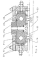
- Figur 4 einen Querschnitt durch eine Gleitführung mit Gleitleisten als Detail.
- Wie aus Figur 1 ersichtlich besteht eine Messermaschine im wesentlichen aus einem Werkzeugschlitten 1 und einer Tischanordnung 2.
- Der Werkzeugschlitten 1 ist auf zwei waagerecht und parallel angeordneten Schienen 3 hin und her beweglich, wie durch den Pfeil 4 symbolisiert. Hierbei ist der Werkzeugschlitten 1 mit Führungselementen 5, die an einem Maschinengestell 6 befestigt sind, mit minimalem Spiel und verdrehsicher auf den Schienen 3 geführt.
- Oben auf dem Maschinengestell 6 ist ein Messerträger 7 mit einem Messer 8 so befestigt, daß er höhenverstellbar, in Richtung des Pfeiles 9 verschiebbar und um die nach unten gerichtete Schneide des Messers 8 drehbar gelagert ist. Dabei ist das Messer 8 in der Seite des Messerträgers 7, die der Tischanordnung 2 gegenüberliegt, angeordnet. Die Verschiebbarkeit des Messerträgers 7 gegenüber dem Maschinengestell 6 entsprechend den Pfeilen 9, 13 und 14, die für die Justierung seiner Lage gegenüber einem unten beschriebenen Druckbalken 12 erforderlich ist, ist über verschiedene Hydraulikzylinder gewährleistet, von denen wegen der Übersichtlichkeit nur zwei mit den Bezugszeichen 10 und 11 dargestellt sind.
- Unterhalb des Messers 8 und parallel dazu ist am Maschinengestell 6 der Druckbalken 12 befestigt. Druckbalken 12 und Messer 8 sind im Betrieb so eingestellt, daß zwischen beiden ein kurzer Abstand eingehalten ist.
- Auf dem Maschinengestell 6 sind weiterhin nicht dargestellte Vorrichtungen für den Austrag der geschnittenen Furnierblätter angeordnet.
- Die Tischanordnung 2, die auch aus Figur 2 ersichtlich ist, besteht im wesentlichen aus einem Maschinengestell 15, Gleitführungen 16, die starr mit dem Maschinengestell 15 verbunden sind, einem Tisch 17 und einem Antrieb mit Motor 18. Die Tischanordnung 2 ist starr auf einem Fundament befestigt und relativ zum Werkzeugschlitten 1 so angeordnet, daß die Schneide des Messers 8 und die Tischebene, auf der ein Holzbalken 19 einspannbar ist, parallel sind. Die Gleitführungen 16 sind fest mit dem Maschinengestell 15 verbunden. Sie bilden jeweils mit einer Vertikalen einen spitzen Winkel, und ihre vom Maschinengestell 15 abgewandten Flächen liegen in einer Ebene. Der Tisch 17 ist mit Hilfe von Gleitleisten 20, die aus mehreren Einzelelementen aufgebaut sind, an den Gleitführungen 16 befestigt, wobei er mittels des Antriebs in einer senkrechten Ebene längs den Gleitführungen 16 auf und ab bewegbar ist. Der Holzbalken 19 ist in üblicher Weise mittels nicht dargestellter hydraulisch betätigter Klauen auf dem Tisch 17 eingespannt.
- Insoweit entspricht die Messermaschine dem Stand der Technik.
- Wie aus Figur 2 und besonders aus den Figuren 3 und 4 ersichtlich, sind an den Gleitführungen 16 jeweils Mittel zu Kühlen angeordnet. Die Mittel zum Kühlen bestehen aus jeweils zwei Kühlkanälen 21 mit zugehörigen Anschlüssen 22 für die Zu- und Ableitung von Kühlmittel sowie gegebenenfalls aus nicht dargestellten Mitteln zur Kreislaufführung und Kühlung des Kühlmittels und zur Regelung.
- Jeder Kühlkanal 21 ist aus zwei Bohrungen 21 a, die sich in etwa parallel zur Längsachse der Gleitführung 16 von einem Ende bis knapp zur Mitte jeder Gleitführung 16 erstrecken, und einer dazu in etwa senkrechten Bohrung 21 b ausgeführt, welche die einem Ende der Gleitführung 16 abgewandten Enden der Bohrungen 21 a verbindet. An den anderen Enden der Bohrungen 21 a sind die Anschlüsse 22 für Rohr- oder Schlauchleitungen angeordnet.
- Der Tisch 17 ist an den Gleitführungen 16 mittels der Gleitleisten 20 beweglich geführt. Die Gleitleisten 20 sind starr mit dem Tisch 17 lösbar verbunden. Zwischen der Gleitleiste 20 und der Gleitführung 16 sind jeweils Verschleißelemente 23 angeordnet; sie sind so lösbar an der Gleitleiste 20 befestigt, daß das Spiel zwischen der Gleitleiste 20 und der Gleitführung 16 einstellbar ist. Hierbei ist das Spiel so klein wie möglich eingestellt, um die Präzision des Schnittes optimal zu gestalten.
- Der Kühlkanal wird hergestellt, indem z.B. zunächst die Bohrungen 21 a ausgeführt werden. Die Bohrung 21 b wird als Verbindung zwischen den Bohrungen 21 a von einer Längsseite der Gleitführung 16 aus vorgetrieben, wobei die seitliche Öffnung anschließend mit einem geeigneten Pfropfen verschlossen wird. Im Querschnitt der Gleitführung 16 ist jede Bohrung 21 a so angeordnet, daß ihr Abstand zu den drei nächstgelegenen Seiten der Gleitführung 16 in etwa gleich groß ist.
- Im Betrieb, der mit Ausnahme der Kühlung der Gleitführungen 16 wie aus dem Stand der Technik bekannt abläuft, ist der Werkzeugschlitten 1 zunächst auf den maximal möglichen Abstand zur Tischanordnung 2 - die sogenannte Ruheposition - zurückgefahren. Es wird ein Holzbalken 19 mit Hilfe der Klauen auf dem Tisch 17 eingespannt und der Werkzeugschlitten 1 in eine Arbeitsposition so vorgefahren, daß ein sehr geringer horizontaler Spalt zwischen dem Holzbalken 17 und der Schneide des Messers 8 bleibt. Der Antrieb für den Tisch 17 wird eingeschaltet und so der Tisch 17 auf und ab bewegt. Bei Erreichen der Soll- Hubzahl und vor einer Aufwärtsbewegung des Tisches 17 wird der Werkzeugschlitten 1 so weit in Richtung des Holzbalkens 19 vorgefahren, daß hiervon während der Aufwärtsbewegung ein Furnierblatt in der einstellbaren Solldicke abgeschnitten wird.
- Sobald der Tisch 17 den oberen Umkehrbereich erreicht hat, fährt der Werkzeugschlitten 1 eine kurze Strecke zurück, so daß der Holzblock 19 während der Abwärtsbewegung das Messer 8 so eben nicht berührt. Im unteren Umkehrbereich des Tisches 17 fährt der Werkzeugschlitten 1 wieder eine Strecke vor, wobei diese Strecke der Solldicke des Furnierblattes zuzüglich der vorher genannten, zurückgefahrenen Strecke entspricht. Dieser Ablauf wird so oft wiederholt, bis so viele Furnierblätter vom Holzblock 17 abgeschnitten sind, daß nur noch ein minimal erforderlicher Rest des Holzblocks 17 übrig ist.
- Zum Entfernen des Restes des Holzblocks 17 wird der Werkzeugschlitten 1 in die Ruheposition zurückgefahren. Es wird ein neuer Holzblock 17 eingespannt, und der Vorgang beginnt von vorne.
- Während der gesamten Betriebszeit sind Mittel zum Kühlen der Gleitführungen 16 eingeschaltet. Diese Mittel sind z.B. eine Pumpe, ein Regelventil, ein Kühler mit Ventilator sowie Steuer- und Regeleinrichtungen.
Claims (5)
- Furniermessermaschine
mit einem hin und her beweglichen Tisch (17) zum Aufspannen eines Holzblocks (19), wobei der Tisch (17) in Gleitführungen (16) mittels Gleitleisten (20) geführt ist,
und mit einem mit Messer (8) und Druckbalken (12) bestückten Werkzeugschlitten (1), der längs einer zur Bewegungsebene des Tisches (17) rechtwinkligen Linie relativ zu dieser Ebene hin und her beweglich ist,
dadurch gekennzeichnet, daß in jeder der Gleitführungen (16) zwei Kühlkanäle (21) oder Bohrungen angeordnet sind, durch die Kühlmittel durchleitbar ist. - Furniermessermaschine nach Anspruch 1 dadurch gekennzeichnet, daß die Durchflußmenge der Kühlflüssigkeit einstellbar ist.
- Furniermessermaschine nach Anspruch 2, dadurch gekennzeichnet, daß eine Regelvorrichtung angeordnet ist.
- Furniermessermaschine nach einem der Ansprüche 1 bis 3, dadurch gekennzeichnet, daß im Zu- oder Ablauf des Kühlmittels zu den Gleitführungen (16) ein Regelventil angeordnet ist.
- Furniermessermaschine nach einem der Ansprüche 1 bis 3, dadurch gekennzeichnet, daß die Drehzahl einer Kühlmittelpumpe veränderbar ist.
Applications Claiming Priority (3)
| Application Number | Priority Date | Filing Date | Title |
|---|---|---|---|
| DE10107255 | 2001-02-16 | ||
| DE10107255A DE10107255C1 (de) | 2001-02-16 | 2001-02-16 | Furniermessermaschine |
| PCT/EP2001/013639 WO2002066213A1 (de) | 2001-02-16 | 2001-11-23 | Furniermessermaschine |
Publications (2)
| Publication Number | Publication Date |
|---|---|
| EP1361939A1 EP1361939A1 (de) | 2003-11-19 |
| EP1361939B1 true EP1361939B1 (de) | 2006-06-07 |
Family
ID=7674273
Family Applications (1)
| Application Number | Title | Priority Date | Filing Date |
|---|---|---|---|
| EP01273770A Expired - Lifetime EP1361939B1 (de) | 2001-02-16 | 2001-11-23 | Furniermessermaschine |
Country Status (12)
| Country | Link |
|---|---|
| US (1) | US6913049B2 (de) |
| EP (1) | EP1361939B1 (de) |
| JP (1) | JP2004517765A (de) |
| KR (1) | KR100572563B1 (de) |
| AT (1) | ATE328712T1 (de) |
| BR (1) | BR0116895B1 (de) |
| CA (1) | CA2437178C (de) |
| DE (2) | DE10107255C1 (de) |
| ES (1) | ES2265393T3 (de) |
| PT (1) | PT1361939E (de) |
| TW (1) | TW576779B (de) |
| WO (1) | WO2002066213A1 (de) |
Families Citing this family (10)
| Publication number | Priority date | Publication date | Assignee | Title |
|---|---|---|---|---|
| US20060086421A1 (en) * | 1998-08-20 | 2006-04-27 | Hartmut Gruender | Drive system for veneer slicer |
| US20060230893A1 (en) * | 2005-04-18 | 2006-10-19 | Brooks Charles A | Method and apparatus for producing mulch |
| US8414996B2 (en) * | 2009-11-06 | 2013-04-09 | Green Rev LLC | Sustainable simulated commodity tropical hardwood panel |
| CN104441074B (zh) * | 2014-11-27 | 2017-02-22 | 曲明春 | 单曲柄立式横向刨切机 |
| DE102016208916B4 (de) | 2016-05-24 | 2024-05-16 | Robert Bosch Gmbh | Führungsschiene mit Befestigungsbohrungen und Kühlkörper |
| CN107139283B (zh) * | 2017-05-19 | 2022-09-06 | 颍上县亚森木业有限责任公司 | 一种胶合板加工用裁切机的出料导向机构 |
| DE102020003605A1 (de) | 2020-06-17 | 2021-12-23 | Alfons Anton Klabes | Schnittstempel mit umlaufenden ständig schmierenden Öltaschen |
| CN112873461A (zh) * | 2021-01-15 | 2021-06-01 | 陆超林 | 一种稳定性好的木材加工用旋切机 |
| US12312501B2 (en) | 2023-05-02 | 2025-05-27 | Greene Rev Llc | Methods and bonding agents for forming simulated tropical hardwood panel |
| US12311570B1 (en) | 2024-07-23 | 2025-05-27 | Greene Rev Llc | Methods and bonding agents for forming wood veneers with no added formaldehyde adhesives |
Family Cites Families (12)
| Publication number | Priority date | Publication date | Assignee | Title |
|---|---|---|---|---|
| US2862532A (en) * | 1955-09-23 | 1958-12-02 | Leighton W Johnson | Gang sawmill |
| FR1238130A (fr) | 1959-10-20 | 1960-08-05 | Perfectionnements aux machines-outils | |
| CH401730A (de) * | 1962-01-12 | 1965-10-31 | Waldrich Werkzeugmasch | Kühleinrichtung für Führungsbahnen von Werkzeugmaschinen |
| FR2273634A1 (fr) * | 1974-06-07 | 1976-01-02 | Ancenis Fab Placages Angebault | Perfectionnements aux machines trancheuses |
| GB1532649A (en) | 1974-12-26 | 1978-11-15 | Monsanto Co | Production of polycrystalline silicon |
| IT1038462B (it) * | 1975-05-28 | 1979-11-20 | Cremona Angelo | Macchina tranciatrice di tronchi di legno per la produzione di impiallicciature presentante il gruppo porta lama posto al disopra del gruppo porta barra |
| DE2928109A1 (de) * | 1979-07-12 | 1981-01-29 | Keller Gmbh & Co Kg | Furniermessermaschine |
| US4587616A (en) * | 1983-05-31 | 1986-05-06 | David R. Webb Co., Inc. | Control system for veneer slicer |
| US4601317A (en) * | 1985-01-31 | 1986-07-22 | Capital Machine Company, Inc. | Veneer slicing system |
| US5511598A (en) * | 1994-04-05 | 1996-04-30 | Capital Machine Company | Veneer-slicer with remotely controllable blade angle adjustment |
| JP2503162B2 (ja) | 1992-06-23 | 1996-06-05 | 株式会社ミヤノ | 熱変位防止装置およびそれを備えた工作機械 |
| US5680887A (en) * | 1995-11-30 | 1997-10-28 | Capital Machine Co., Inc. | Veneer slicer with timing belt |
-
2001
- 2001-02-16 DE DE10107255A patent/DE10107255C1/de not_active Expired - Fee Related
- 2001-11-23 US US10/467,613 patent/US6913049B2/en not_active Expired - Fee Related
- 2001-11-23 PT PT01273770T patent/PT1361939E/pt unknown
- 2001-11-23 JP JP2002565754A patent/JP2004517765A/ja active Pending
- 2001-11-23 BR BRPI0116895-9A patent/BR0116895B1/pt not_active IP Right Cessation
- 2001-11-23 ES ES01273770T patent/ES2265393T3/es not_active Expired - Lifetime
- 2001-11-23 WO PCT/EP2001/013639 patent/WO2002066213A1/de not_active Ceased
- 2001-11-23 AT AT01273770T patent/ATE328712T1/de active
- 2001-11-23 KR KR1020037010653A patent/KR100572563B1/ko not_active Expired - Fee Related
- 2001-11-23 CA CA002437178A patent/CA2437178C/en not_active Expired - Fee Related
- 2001-11-23 DE DE50110082T patent/DE50110082D1/de not_active Expired - Lifetime
- 2001-11-23 EP EP01273770A patent/EP1361939B1/de not_active Expired - Lifetime
- 2001-12-20 TW TW090131610A patent/TW576779B/zh not_active IP Right Cessation
Also Published As
| Publication number | Publication date |
|---|---|
| CA2437178A1 (en) | 2002-08-29 |
| ATE328712T1 (de) | 2006-06-15 |
| DE50110082D1 (de) | 2006-07-20 |
| BR0116895B1 (pt) | 2011-11-16 |
| WO2002066213A1 (de) | 2002-08-29 |
| DE10107255C1 (de) | 2002-06-20 |
| BR0116895A (pt) | 2004-06-15 |
| US6913049B2 (en) | 2005-07-05 |
| KR20030078912A (ko) | 2003-10-08 |
| TW576779B (en) | 2004-02-21 |
| PT1361939E (pt) | 2006-10-31 |
| JP2004517765A (ja) | 2004-06-17 |
| ES2265393T3 (es) | 2007-02-16 |
| KR100572563B1 (ko) | 2006-04-24 |
| CA2437178C (en) | 2007-05-01 |
| EP1361939A1 (de) | 2003-11-19 |
| US20040094232A1 (en) | 2004-05-20 |
Similar Documents
| Publication | Publication Date | Title |
|---|---|---|
| EP0418779B1 (de) | Verfahren zum Herstellen von Werkstücken durch Schneiden, insbesondere in einem Konterschneidwerkzeug | |
| EP2228160B1 (de) | Druckmittelgesteuertes Senkwerkzeug | |
| DE10107255C1 (de) | Furniermessermaschine | |
| DE202011101665U1 (de) | Plattenaufteilsäge mit Absaugung | |
| EP0967041B1 (de) | Verfahren und Vorrichtung zum Führen des Sägebandes einer Bandsägemaschine | |
| EP1600254A1 (de) | Vorschubeinheit für eine Maschine zum Bearbeiten von Werkstücken sowie Verfahren zum Bearbeiten solcher Werkstücke | |
| CH656828A5 (de) | Schneidmaschine zum beschneiden von broschueren. | |
| DE2912662C2 (de) | ||
| DE1934847C3 (de) | Ausklinkvorrichtung | |
| DE69231504T2 (de) | Revolverstanzmaschine | |
| DE102016120139B4 (de) | Verfahren, Werkzeugmaschine und Schlitzwerkzeug zum mehrhubig fortschreitenden Schlitzen von plattenförmigen Werkstücken | |
| EP0811438A2 (de) | Trenn- und Ausklinkvorrichtung für perforierte Bleche | |
| DE29817770U1 (de) | Spanabhende Werkzeugmaschine, insbesondere Holzbearbeitungsmaschine für Fenster-, Tür- und Fassadenprofile sowie Werkzeugaggregate für eine Werkzeugmaschine | |
| DE3108337A1 (de) | Strangpressmaschine und verfahren zum betrieb einer strangpressmaschine | |
| DE10234279C1 (de) | Furniermessermaschine | |
| DE202011102022U1 (de) | Sägemaschine mit Druckbalken | |
| DE1502668A1 (de) | Verfahren und Maschine zum Abschneiden von mit Innenkanaelen versehenen Werkstuecken | |
| EP1572427B1 (de) | Furniermessermaschine | |
| DE2741918A1 (de) | Werkzeugmaschine mit einrichtungen zum wahlweisen anbringen eines keilnuten- ziehmessers und eines raeumwerkzeuges | |
| DE10112294A1 (de) | Vorrichtung zum Abführen und Zerkleinern des in einer Rohrschweißanlage von der äußeren Rohroberfläche abgetragenen Spanes | |
| DE69501684T2 (de) | Rolltisch für Werkzeugmaschinen, insbesondere für Holzbearbeitungsmaschinen | |
| EP0982092A2 (de) | Staubschutzvorhang für Sägemaschinen insbesonderer Plattenaufteilsägen | |
| DE763919C (de) | Einrichtung zum taktmaessigen Heben und Senken des Werkstueckaufspann-tisches an Fraesmaschinen mit Hilfe eines Keilschiebers | |
| EP1613452B1 (de) | Furniermessermaschine | |
| DE10037144A1 (de) | Stanzeinrichtung |
Legal Events
| Date | Code | Title | Description |
|---|---|---|---|
| PUAI | Public reference made under article 153(3) epc to a published international application that has entered the european phase |
Free format text: ORIGINAL CODE: 0009012 |
|
| 17P | Request for examination filed |
Effective date: 20030916 |
|
| AK | Designated contracting states |
Kind code of ref document: A1 Designated state(s): AT BE CH CY DE DK ES FI FR GB GR IE IT LI LU MC NL PT SE TR |
|
| AX | Request for extension of the european patent |
Extension state: AL LT LV MK SI |
|
| 17Q | First examination report despatched |
Effective date: 20041217 |
|
| GRAP | Despatch of communication of intention to grant a patent |
Free format text: ORIGINAL CODE: EPIDOSNIGR1 |
|
| GRAS | Grant fee paid |
Free format text: ORIGINAL CODE: EPIDOSNIGR3 |
|
| GRAA | (expected) grant |
Free format text: ORIGINAL CODE: 0009210 |
|
| AK | Designated contracting states |
Kind code of ref document: B1 Designated state(s): AT BE CH CY DE DK ES FI FR GB GR IE IT LI LU MC NL PT SE TR |
|
| AX | Request for extension of the european patent |
Extension state: AL LT LV MK SI |
|
| PG25 | Lapsed in a contracting state [announced via postgrant information from national office to epo] |
Ref country code: IT Free format text: LAPSE BECAUSE OF FAILURE TO SUBMIT A TRANSLATION OF THE DESCRIPTION OR TO PAY THE FEE WITHIN THE PRESCRIBED TIME-LIMIT;WARNING: LAPSES OF ITALIAN PATENTS WITH EFFECTIVE DATE BEFORE 2007 MAY HAVE OCCURRED AT ANY TIME BEFORE 2007. THE CORRECT EFFECTIVE DATE MAY BE DIFFERENT FROM THE ONE RECORDED. Effective date: 20060607 Ref country code: NL Free format text: LAPSE BECAUSE OF FAILURE TO SUBMIT A TRANSLATION OF THE DESCRIPTION OR TO PAY THE FEE WITHIN THE PRESCRIBED TIME-LIMIT Effective date: 20060607 Ref country code: IE Free format text: LAPSE BECAUSE OF FAILURE TO SUBMIT A TRANSLATION OF THE DESCRIPTION OR TO PAY THE FEE WITHIN THE PRESCRIBED TIME-LIMIT Effective date: 20060607 Ref country code: FI Free format text: LAPSE BECAUSE OF FAILURE TO SUBMIT A TRANSLATION OF THE DESCRIPTION OR TO PAY THE FEE WITHIN THE PRESCRIBED TIME-LIMIT Effective date: 20060607 Ref country code: GB Free format text: LAPSE BECAUSE OF FAILURE TO SUBMIT A TRANSLATION OF THE DESCRIPTION OR TO PAY THE FEE WITHIN THE PRESCRIBED TIME-LIMIT Effective date: 20060607 |
|
| REG | Reference to a national code |
Ref country code: GB Ref legal event code: FG4D Free format text: NOT ENGLISH |
|
| REG | Reference to a national code |
Ref country code: CH Ref legal event code: EP |
|
| REG | Reference to a national code |
Ref country code: IE Ref legal event code: FG4D Free format text: LANGUAGE OF EP DOCUMENT: GERMAN |
|
| REF | Corresponds to: |
Ref document number: 50110082 Country of ref document: DE Date of ref document: 20060720 Kind code of ref document: P |
|
| PG25 | Lapsed in a contracting state [announced via postgrant information from national office to epo] |
Ref country code: DK Free format text: LAPSE BECAUSE OF FAILURE TO SUBMIT A TRANSLATION OF THE DESCRIPTION OR TO PAY THE FEE WITHIN THE PRESCRIBED TIME-LIMIT Effective date: 20060907 Ref country code: SE Free format text: LAPSE BECAUSE OF FAILURE TO SUBMIT A TRANSLATION OF THE DESCRIPTION OR TO PAY THE FEE WITHIN THE PRESCRIBED TIME-LIMIT Effective date: 20060907 |
|
| REG | Reference to a national code |
Ref country code: PT Ref legal event code: SC4A Effective date: 20060817 |
|
| PG25 | Lapsed in a contracting state [announced via postgrant information from national office to epo] |
Ref country code: MC Free format text: LAPSE BECAUSE OF NON-PAYMENT OF DUE FEES Effective date: 20061130 Ref country code: LI Free format text: LAPSE BECAUSE OF NON-PAYMENT OF DUE FEES Effective date: 20061130 Ref country code: BE Free format text: LAPSE BECAUSE OF NON-PAYMENT OF DUE FEES Effective date: 20061130 Ref country code: CH Free format text: LAPSE BECAUSE OF NON-PAYMENT OF DUE FEES Effective date: 20061130 |
|
| NLV1 | Nl: lapsed or annulled due to failure to fulfill the requirements of art. 29p and 29m of the patents act | ||
| ET | Fr: translation filed | ||
| GBV | Gb: ep patent (uk) treated as always having been void in accordance with gb section 77(7)/1977 [no translation filed] |
Effective date: 20060607 |
|
| REG | Reference to a national code |
Ref country code: ES Ref legal event code: FG2A Ref document number: 2265393 Country of ref document: ES Kind code of ref document: T3 |
|
| REG | Reference to a national code |
Ref country code: IE Ref legal event code: FD4D |
|
| PLBE | No opposition filed within time limit |
Free format text: ORIGINAL CODE: 0009261 |
|
| STAA | Information on the status of an ep patent application or granted ep patent |
Free format text: STATUS: NO OPPOSITION FILED WITHIN TIME LIMIT |
|
| 26N | No opposition filed |
Effective date: 20070308 |
|
| REG | Reference to a national code |
Ref country code: CH Ref legal event code: PL |
|
| BERE | Be: lapsed |
Owner name: GRENZEBACH BSH G.M.B.H. Effective date: 20061130 |
|
| PG25 | Lapsed in a contracting state [announced via postgrant information from national office to epo] |
Ref country code: GR Free format text: LAPSE BECAUSE OF FAILURE TO SUBMIT A TRANSLATION OF THE DESCRIPTION OR TO PAY THE FEE WITHIN THE PRESCRIBED TIME-LIMIT Effective date: 20060908 |
|
| PG25 | Lapsed in a contracting state [announced via postgrant information from national office to epo] |
Ref country code: LU Free format text: LAPSE BECAUSE OF NON-PAYMENT OF DUE FEES Effective date: 20061123 |
|
| PG25 | Lapsed in a contracting state [announced via postgrant information from national office to epo] |
Ref country code: CY Free format text: LAPSE BECAUSE OF FAILURE TO SUBMIT A TRANSLATION OF THE DESCRIPTION OR TO PAY THE FEE WITHIN THE PRESCRIBED TIME-LIMIT Effective date: 20060607 |
|
| PGFP | Annual fee paid to national office [announced via postgrant information from national office to epo] |
Ref country code: FR Payment date: 20121203 Year of fee payment: 12 |
|
| PGFP | Annual fee paid to national office [announced via postgrant information from national office to epo] |
Ref country code: TR Payment date: 20121123 Year of fee payment: 12 Ref country code: PT Payment date: 20120523 Year of fee payment: 12 Ref country code: ES Payment date: 20121107 Year of fee payment: 12 |
|
| PGFP | Annual fee paid to national office [announced via postgrant information from national office to epo] |
Ref country code: AT Payment date: 20121127 Year of fee payment: 12 |
|
| PGFP | Annual fee paid to national office [announced via postgrant information from national office to epo] |
Ref country code: IT Payment date: 20130925 Year of fee payment: 13 |
|
| PGFP | Annual fee paid to national office [announced via postgrant information from national office to epo] |
Ref country code: DE Payment date: 20131126 Year of fee payment: 13 |
|
| REG | Reference to a national code |
Ref country code: PT Ref legal event code: MM4A Free format text: LAPSE DUE TO NON-PAYMENT OF FEES Effective date: 20140523 |
|
| REG | Reference to a national code |
Ref country code: AT Ref legal event code: MM01 Ref document number: 328712 Country of ref document: AT Kind code of ref document: T Effective date: 20131123 |
|
| REG | Reference to a national code |
Ref country code: LT Ref legal event code: MM9D Effective date: 20131123 |
|
| REG | Reference to a national code |
Ref country code: FR Ref legal event code: ST Effective date: 20140731 |
|
| PG25 | Lapsed in a contracting state [announced via postgrant information from national office to epo] |
Ref country code: PT Free format text: LAPSE BECAUSE OF NON-PAYMENT OF DUE FEES Effective date: 20140523 Ref country code: AT Free format text: LAPSE BECAUSE OF NON-PAYMENT OF DUE FEES Effective date: 20131123 |
|
| PG25 | Lapsed in a contracting state [announced via postgrant information from national office to epo] |
Ref country code: FR Free format text: LAPSE BECAUSE OF NON-PAYMENT OF DUE FEES Effective date: 20131202 |
|
| REG | Reference to a national code |
Ref country code: ES Ref legal event code: FD2A Effective date: 20150504 |
|
| REG | Reference to a national code |
Ref country code: DE Ref legal event code: R119 Ref document number: 50110082 Country of ref document: DE |
|
| PG25 | Lapsed in a contracting state [announced via postgrant information from national office to epo] |
Ref country code: ES Free format text: LAPSE BECAUSE OF NON-PAYMENT OF DUE FEES Effective date: 20131124 |
|
| PG25 | Lapsed in a contracting state [announced via postgrant information from national office to epo] |
Ref country code: TR Free format text: LAPSE BECAUSE OF NON-PAYMENT OF DUE FEES Effective date: 20131123 |
|
| PG25 | Lapsed in a contracting state [announced via postgrant information from national office to epo] |
Ref country code: DE Free format text: LAPSE BECAUSE OF NON-PAYMENT OF DUE FEES Effective date: 20150602 |
|
| PG25 | Lapsed in a contracting state [announced via postgrant information from national office to epo] |
Ref country code: IT Free format text: LAPSE BECAUSE OF NON-PAYMENT OF DUE FEES Effective date: 20141123 |