EP1361105A2 - Fahrzeugsitz, insbesondere für Lastkraftwagen, Omnibusse od. dgl - Google Patents
Fahrzeugsitz, insbesondere für Lastkraftwagen, Omnibusse od. dgl Download PDFInfo
- Publication number
- EP1361105A2 EP1361105A2 EP03009028A EP03009028A EP1361105A2 EP 1361105 A2 EP1361105 A2 EP 1361105A2 EP 03009028 A EP03009028 A EP 03009028A EP 03009028 A EP03009028 A EP 03009028A EP 1361105 A2 EP1361105 A2 EP 1361105A2
- Authority
- EP
- European Patent Office
- Prior art keywords
- vehicle seat
- gear
- seat according
- seat cushion
- axis
- Prior art date
- Legal status (The legal status is an assumption and is not a legal conclusion. Google has not performed a legal analysis and makes no representation as to the accuracy of the status listed.)
- Granted
Links
Images


Classifications
-
- B—PERFORMING OPERATIONS; TRANSPORTING
- B60—VEHICLES IN GENERAL
- B60N—SEATS SPECIALLY ADAPTED FOR VEHICLES; VEHICLE PASSENGER ACCOMMODATION NOT OTHERWISE PROVIDED FOR
- B60N2/00—Seats specially adapted for vehicles; Arrangement or mounting of seats in vehicles
- B60N2/02—Seats specially adapted for vehicles; Arrangement or mounting of seats in vehicles the seat or part thereof being movable, e.g. adjustable
- B60N2/04—Seats specially adapted for vehicles; Arrangement or mounting of seats in vehicles the seat or part thereof being movable, e.g. adjustable the whole seat being movable
- B60N2/16—Seats specially adapted for vehicles; Arrangement or mounting of seats in vehicles the seat or part thereof being movable, e.g. adjustable the whole seat being movable height-adjustable
- B60N2/18—Seats specially adapted for vehicles; Arrangement or mounting of seats in vehicles the seat or part thereof being movable, e.g. adjustable the whole seat being movable height-adjustable the front or the rear portion of the seat being adjustable, e.g. independently of each other
- B60N2/1807—Seats specially adapted for vehicles; Arrangement or mounting of seats in vehicles the seat or part thereof being movable, e.g. adjustable the whole seat being movable height-adjustable the front or the rear portion of the seat being adjustable, e.g. independently of each other characterised by the cinematic
- B60N2/181—Rods
-
- B—PERFORMING OPERATIONS; TRANSPORTING
- B60—VEHICLES IN GENERAL
- B60N—SEATS SPECIALLY ADAPTED FOR VEHICLES; VEHICLE PASSENGER ACCOMMODATION NOT OTHERWISE PROVIDED FOR
- B60N2/00—Seats specially adapted for vehicles; Arrangement or mounting of seats in vehicles
- B60N2/02—Seats specially adapted for vehicles; Arrangement or mounting of seats in vehicles the seat or part thereof being movable, e.g. adjustable
- B60N2/0224—Non-manual adjustments, e.g. with electrical operation
- B60N2/0226—User interfaces specially adapted for seat adjustment
- B60N2/0231—User interfaces specially adapted for seat adjustment concealed interfaces, e.g. hidden below seat cover
-
- B—PERFORMING OPERATIONS; TRANSPORTING
- B60—VEHICLES IN GENERAL
- B60N—SEATS SPECIALLY ADAPTED FOR VEHICLES; VEHICLE PASSENGER ACCOMMODATION NOT OTHERWISE PROVIDED FOR
- B60N2/00—Seats specially adapted for vehicles; Arrangement or mounting of seats in vehicles
- B60N2/02—Seats specially adapted for vehicles; Arrangement or mounting of seats in vehicles the seat or part thereof being movable, e.g. adjustable
- B60N2/0224—Non-manual adjustments, e.g. with electrical operation
- B60N2/02246—Electric motors therefor
- B60N2/02253—Electric motors therefor characterised by the transmission between the electric motor and the seat or seat parts
-
- B—PERFORMING OPERATIONS; TRANSPORTING
- B60—VEHICLES IN GENERAL
- B60N—SEATS SPECIALLY ADAPTED FOR VEHICLES; VEHICLE PASSENGER ACCOMMODATION NOT OTHERWISE PROVIDED FOR
- B60N2/00—Seats specially adapted for vehicles; Arrangement or mounting of seats in vehicles
- B60N2/02—Seats specially adapted for vehicles; Arrangement or mounting of seats in vehicles the seat or part thereof being movable, e.g. adjustable
- B60N2/04—Seats specially adapted for vehicles; Arrangement or mounting of seats in vehicles the seat or part thereof being movable, e.g. adjustable the whole seat being movable
- B60N2/16—Seats specially adapted for vehicles; Arrangement or mounting of seats in vehicles the seat or part thereof being movable, e.g. adjustable the whole seat being movable height-adjustable
- B60N2/18—Seats specially adapted for vehicles; Arrangement or mounting of seats in vehicles the seat or part thereof being movable, e.g. adjustable the whole seat being movable height-adjustable the front or the rear portion of the seat being adjustable, e.g. independently of each other
- B60N2/1807—Seats specially adapted for vehicles; Arrangement or mounting of seats in vehicles the seat or part thereof being movable, e.g. adjustable the whole seat being movable height-adjustable the front or the rear portion of the seat being adjustable, e.g. independently of each other characterised by the cinematic
- B60N2/1839—Seats specially adapted for vehicles; Arrangement or mounting of seats in vehicles the seat or part thereof being movable, e.g. adjustable the whole seat being movable height-adjustable the front or the rear portion of the seat being adjustable, e.g. independently of each other characterised by the cinematic pivoting about an axis located in an intermediate position
-
- B—PERFORMING OPERATIONS; TRANSPORTING
- B60—VEHICLES IN GENERAL
- B60N—SEATS SPECIALLY ADAPTED FOR VEHICLES; VEHICLE PASSENGER ACCOMMODATION NOT OTHERWISE PROVIDED FOR
- B60N2/00—Seats specially adapted for vehicles; Arrangement or mounting of seats in vehicles
- B60N2/02—Seats specially adapted for vehicles; Arrangement or mounting of seats in vehicles the seat or part thereof being movable, e.g. adjustable
- B60N2/04—Seats specially adapted for vehicles; Arrangement or mounting of seats in vehicles the seat or part thereof being movable, e.g. adjustable the whole seat being movable
- B60N2/16—Seats specially adapted for vehicles; Arrangement or mounting of seats in vehicles the seat or part thereof being movable, e.g. adjustable the whole seat being movable height-adjustable
- B60N2/18—Seats specially adapted for vehicles; Arrangement or mounting of seats in vehicles the seat or part thereof being movable, e.g. adjustable the whole seat being movable height-adjustable the front or the rear portion of the seat being adjustable, e.g. independently of each other
- B60N2/185—Seats specially adapted for vehicles; Arrangement or mounting of seats in vehicles the seat or part thereof being movable, e.g. adjustable the whole seat being movable height-adjustable the front or the rear portion of the seat being adjustable, e.g. independently of each other characterised by the drive mechanism
- B60N2/1864—Gear wheel driven mechanism
-
- B—PERFORMING OPERATIONS; TRANSPORTING
- B60—VEHICLES IN GENERAL
- B60N—SEATS SPECIALLY ADAPTED FOR VEHICLES; VEHICLE PASSENGER ACCOMMODATION NOT OTHERWISE PROVIDED FOR
- B60N2/00—Seats specially adapted for vehicles; Arrangement or mounting of seats in vehicles
- B60N2/02—Seats specially adapted for vehicles; Arrangement or mounting of seats in vehicles the seat or part thereof being movable, e.g. adjustable
- B60N2/04—Seats specially adapted for vehicles; Arrangement or mounting of seats in vehicles the seat or part thereof being movable, e.g. adjustable the whole seat being movable
- B60N2/16—Seats specially adapted for vehicles; Arrangement or mounting of seats in vehicles the seat or part thereof being movable, e.g. adjustable the whole seat being movable height-adjustable
- B60N2/18—Seats specially adapted for vehicles; Arrangement or mounting of seats in vehicles the seat or part thereof being movable, e.g. adjustable the whole seat being movable height-adjustable the front or the rear portion of the seat being adjustable, e.g. independently of each other
- B60N2/1885—Seats specially adapted for vehicles; Arrangement or mounting of seats in vehicles the seat or part thereof being movable, e.g. adjustable the whole seat being movable height-adjustable the front or the rear portion of the seat being adjustable, e.g. independently of each other with weight compensating means
-
- B—PERFORMING OPERATIONS; TRANSPORTING
- B60—VEHICLES IN GENERAL
- B60N—SEATS SPECIALLY ADAPTED FOR VEHICLES; VEHICLE PASSENGER ACCOMMODATION NOT OTHERWISE PROVIDED FOR
- B60N2/00—Seats specially adapted for vehicles; Arrangement or mounting of seats in vehicles
- B60N2/24—Seats specially adapted for vehicles; Arrangement or mounting of seats in vehicles for particular purposes or particular vehicles
- B60N2/242—Bus seats
Definitions
- the invention relates to a vehicle seat, in particular for trucks, Buses or the like.
- a vehicle seat is the subject of the older ones DE 101 09 526 A1.
- the seat cushion carrier has in its front area two protruding down towards the seat base frame front extensions on which a horizontal pivot axis for articulation of the front area of the seat cushion support on the seat base frame. Below its rear area, the seat cushion support faces two down protruding rear projections towards the seat base frame, at their free Each end of an adjusting gear, namely a screw drive, articulated is.
- the rear area of the seat cushion support can be around the front horizontal pivot axis into an operating position raised or lowered to a rest position.
- the invention has for its object a vehicle seat with a compact and to create a sensitive adjustment device.
- the drive connected to a motor at least one adjustment gear designed as a reduction gear Crank drives, which is horizontal in a vertical plane of rotation and parallel to the pivot axis extending axis of rotation over a limited Angle of rotation can be rotated back and forth, and the free crank end articulated at least indirectly to the rear area of the seat cushion support is.
- An advantage of the vehicle seat according to the invention is that only a reduction gear for driving the at least one crank and a motor are required, and a compact structure is achieved that can hardly be realized in the vehicle seat according to DE 101 09 526 A1. By selecting a reduction gear with a relatively large reduction you can also achieve a sensitive adjustment.
- a particularly robust construction is in accordance with further features of the invention was created in that a hinge plate with her inner end at the free end of the crank and with its outer end at the rear Area of the seat support is articulated, one with regard to the force distribution particularly favorable arrangement is that the reduction gear two identically oriented cranks arranged on a common axis of rotation drives.
- the invention accordingly uses an articulated gearbox, specifically a crank arm, in which the coupling is each from a hinge plate and the swing arm overall from the one with its front area to the horizontal swivel axis on the seat base frame hinged seat cushion support is formed.
- Another embodiment of the invention that is uniform Allowing force distribution is the underside of the rear area the seat cushion support an actuation axis extending parallel to the pivot axis is coupled to the two cranks, each on Crank is articulated a link plate, the outer end of each the actuation axis encompasses with a pivot bearing.
- the seat cushion support raising or lowering adjustment device forms the seat cushion support raising or lowering adjustment device as part of the seat base frame an approximately insert-like assembly.
- Such an assembly can largely prefabricated and as a uniform module for otherwise individual equipped vehicle seats serve.
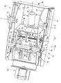
- a vehicle seat In Fig. 1, the structure of a vehicle seat is generally designated 10. On a bracket 11 to be fastened on the vehicle side is a along the Direction of travel x longitudinally adjustable seat base frame 12, which a generally designated 13, approximately insert-like assembly 13 in one Seat frame box 14 takes.
- the insert-like assembly 13 has two transverse distances from one another distanced longitudinal leg 15, which is fixed by means of a transverse leg 16 are interconnected.
- the longitudinal legs 15 In their upper regions, the longitudinal legs 15 have a convex shape arcuate contour and there form two bearing receptacles 17, in which from the outside, a bearing pin 18 of a seat cushion support 19 is inserted is.
- the two bearing receptacles 17 of the assembly 13 and the two bearing journals 18 of the seat cushion support 19 form a pivot axis in this way, whose geometric straight line is entered with dash-dot lines and with S is designated.
- the front area of the seat cushion support 19 bears the reference symbol V, while the rear region of the seat cushion support 19 with the Reference symbol R is provided.
- the seat cushion support 19 with two Crosswise spaced fittings 20, only one of which is shown for attaching a seat back, not shown.
- the cross leg 16 is arranged inclined to the horizontal plane and bears on its front region V of the seat cushion support 19 Main surface of a motor M, namely a 24 V DC motor, the Axis of rotation DM e.g. is indicated in Fig. 1 with a dashed straight line.
- a coherent gear housing block 22 attached, which contains a worm gear 23 and a spur gear 24.
- the axis of rotation for the Output of the worm gear 23 and the axis of rotation for the output of the Helical gear 24 extend at right angles to the axis of rotation DM of the motor M.
- the output of the spur gear 24 takes place via a Star shaft 25 trained intermediate shaft, whose dashed line Axis of rotation is designated DW.
- each Planetary gear 26 is facing away from the spur gear 24 Gear housing side 27 on the inner main surface 28 each of a longitudinal leg 15 attached.
- the output side of the spur gear 24 Planetary gear 26, however, is designed as a rotatable cover-like insert 29, which carries a crank K on its outer surface.
- the lid-like Insert 29 is in FIGS. 2 and 6 each with a circular broken line contour characterized.
- the axis of rotation DW also forms the common one geometric axis of rotation for the two cranks K.
- Each crank K has a free crank end 30, which each with the inner end 31 of a hinge plate G by means of a respective bearing pin 32 is articulated.
- Each free end 33 of an articulated strap G engages in parallel to the pivot axis S extending actuator axis 34 with a pivot bearing.
- the assembly 13 has two cranks K, which are at the same distance are arranged to a vertical plane of symmetry, which in Fig. 3 as dash-dotted parallelogram is indicated and labeled SE.
- the actuation axis 34 represents a tube with a circular cross section
- the actuation axis 34 engages in one between two longitudinal struts 35 of the seat cushion support 19 (see FIG. 1) formed underside 36 a, in each longitudinal strut 35 a plug 37 is held, which each engages in an end opening 38 of the actuation axis 34.
- Both Hinged brackets G can, moreover, be rigid by means of a truss arrangement 39 be connected.
- the seat cushion support 19 has on its two long sides (at 35) in each case one through which the pivot axis S passes through the mounting bracket 40, at the free end each a coil spring 42 with its movable end 43 (see FIG. 5) is attached, the one facing away from the front seat cushion area V. other end 44 on the seat base frame 12, namely on the insert 13, is set.
- the insert 13 has an annular groove Holding bolt 46 on each long side.
- the motor M As soon as the motor M is supplied with electrical power, turns the motor shaft arranged in the motor axis of rotation DM, the induced Speed first over the worm gear 23 and then over the Helical gear 24 is reduced.
- the angle of rotation of the two cranks K can be determined by suitable measures, e.g. limited by the motor M controlling micro or proximity switches.
- the seat cushion support 19 is around the pivot axis S around in the direction H upwards or in the direction B downwards pivoted below.
- the swivel in direction H is carried out with Support of the relaxing coil tension springs 42.
- the planetary gear 26 of the type described are of the FAURECIA SIEGES D'AUTOMOBILE S.A. Le Bois de Flers, FR, accordingly the drawing number 9420084 J manufactured and distributed.
Landscapes
- Engineering & Computer Science (AREA)
- Aviation & Aerospace Engineering (AREA)
- Transportation (AREA)
- Mechanical Engineering (AREA)
- Human Computer Interaction (AREA)
- Seats For Vehicles (AREA)
Abstract
Description
Claims (16)
- Fahrzeugsitz, insbesondere für Lastkraftwagen, Omnibusse od. dgl., mit einem Sitzgrundgestell (12) und mit einem oberhalb des Sitzgrundgestells (12) angeordneten Sitzkissenträger (19), dessen vorderer Bereich (V) mittels einer horizontalen Schwenkachse (S) am Sitzgrundgestell (12) angelenkt ist und an dessen hinterem Bereich (R) ein letzteren anhebendes oder absenkendes Verstellgetriebe (23, 24, 26) mindestens mittelbar angreift, dadurch gekennzeichnet, dass das mit einem Motor (M) antriebsverbundene, als Untersetzungsgetriebe (23, 24, 26) ausgebildete Verstellgetriebe mindestens eine Kurbel (K) antreibt, welche in einer vertikalen Drehebene um eine sich horizontal und parallel zur Schwenkachse (S) erstreckenden Drehachse (DW) über einen begrenzten Drehwinkel hin- und hergehend drehbar ist, und wobei das freie Kurbelende (30) mindestens mittelbar an dem hinteren Bereich (R) des Sitzkissenträgers (19) angelenkt ist.
- Fahrzeugsitz nach Anspruch 1, dadurch gekennzeichnet, dass das freie Kurbelende (30) ein Rollen- oder Gleitelement trägt, welches in einem länglichen Führungsschlitz geführt ist, der am hinteren Bereich (R) des Sitzkissenträgers (19) gebildet ist und dessen Längsrichtung etwa radial zur Schwenkachse (S) angeordnet ist.
- Fahrzeugsitz nach Anspruch 1, dadurch gekennzeichnet, dass eine Gelenklasche (G) mit ihrem inneren Ende (31) am freien Kurbelende (30) und mit ihrem äußeren Ende (33) mindestens mittelbar am hinteren Bereich (R) des Sitzkissenträgers (19) angelenkt ist.
- Fahrzeugsitz nach einem der Ansprüche 1 bis 3, dadurch gekennzeichnet, dass das Untersetzungsgetriebe (23, 24, 26) zwei auf einer gemeinsamen Drehachse (DW) angeordnete, gleich orientierte Kurbeln (K) antreibt.
- Fahrzeugsitz nach Anspruch 4, dadurch gekennzeichnet, dass die beiden Kurbeln (K) im gleichen Abstand zu einer vertikalen Symmetrieebene (SE) des Fahrzeugsitzes angeordnet sind.
- Fahrzeugsitz nach einem der Ansprüche 3 bis 5, dadurch gekennzeichnet, dass unterseitig des hinteren Bereich (R) des Sitzkissenträgers (19) eine sich parallel zur Schwenkachse (S) erstreckende Betätigungsachse (34) mit den beiden Kurbeln (K) bewegungsgekoppelt ist, wobei an jeder Kurbel (K) eine Gelenklasche (G) angelenkt ist, deren äußeres Ende (33) jeweils die Betätigungsachse (34) mit einer Drehlagerstelle umgreift.
- Fahrzeugsitz nach Anspruch 6, dadurch gekennzeichnet, dass die Betätigungsachse (34) in einen zwischen zwei Längsstreben (35) des Sitzkissenträgers (19) gebildeten unterseitigen Zwischenraum (36) eingreift und dass in jeder Längsstrebe (35) ein Steckzapfen (37) gehalten ist, welcher jeweils in eine stirnseitige Öffnung (38) der Betätigungsachse (34) eingreift.
- Fahrzeugsitz nach Anspruch 6 oder nach Anspruch 7, dadurch gekennzeichnet, dass die Betätigungsachse (34) ein Rohr mit kreisförmigem Querschnitt ist.
- Fahrzeugsitz nach einem der Ansprüche 1 bis 8, gekennzeichnet durch einen Antriebsmotor (M), dessen Motordrehachse (DM) etwa in der oder parallel zu der vertikalen Symmetrieebene (SE) angeordnet ist und an welchen abtriebsseitig das Untersetzungsgetriebe (23, 24, 26) angeschlossen ist, welches motorabtriebsseitig zunächst ein Schneckengetriebe (23), und im Kraftfluss aufeinanderfolgend, ein Stirnradgetriebe (24) und schließlich mindestens ein jeweils eine Kurbel (K) antreibendes Planetengetriebe (26) aufweist.
- Fahrzeugsitz nach Anspruch 9, dadurch gekennzeichnet, dass das Gehäuse (22) des Stirnradgetriebes (24) abtriebseitig von einer Zwischenwelle (25) durchsetzt ist, deren beiden Enden jeweils antriebsseitig in ein Planetengetriebe (26) eingreifen, dessen dem Stirnradgetriebe (24) abgewandte Getriebegehäuseseite (27) jeweils innenseitig am Sitzgrundgestell befestigt ist, während eine dem Stirnradgetriebe (24) zugewandte Abtriebsseite des Planetengetriebes (26) als drehbarer deckelartiger Einsatz (29) ausgebildet ist, an dessen Außenfläche jeweils eine Kurbel (K) befestigt ist, und wobei Kurbel (K) und drehbarer deckelartiger Einsatz (29) von der Zwischenwelle (25) mit Spiel durchsetzt sind.
- Fahrzeugsitz nach einem der Ansprüche 1 bis 10, dadurch gekennzeichnet, dass der hintere Bereich (R) des Sitzkissenträgers (19) entgegen der Rückstellkraft mindestens eines Federelements (42) absenkbar ist.
- Fahrzeugsitz nach Anspruch 11, dadurch gekennzeichnet, dass der Sitzkissenträger (19) an beiden Längsseiten jeweils eine von der Schwenkachse (S) durchsetzte Haltelasche (40) aufweist, an deren freiem Ende (41) jeweils eine Schraubenzugfeder (42) mit ihrem beweglichen Ende (43) befestigt ist, deren dem vorderen Sitzkissenbereich (V) abgewandtes anderes Ende (44) am Sitzgrundgestell (12) festgelegt ist.
- Fahrzeugsitz nach einem der Ansprüche 1 bis 12, dadurch gekennzeichnet, dass die den Sitzkissenträger (19) anhebende und absenkende Verstellvorrichtung als Bestandteil des Sitzgrundgestells (12) eine etwa einsatzartige Baugruppe (13) bildet.
- Fahrzeugsitz nach Anspruch 13, dadurch gekennzeichnet, dass die etwa einsatzartige Baugruppe (13) zwei sich parallel zur vertikalen Symmetrieebene (SE) erstreckenden Längsschenkeln (15) und mindestens einen die beiden Längsschenkel (15) miteinander verbindenden Querschenkel (16) aufweist.
- Fahrzeugsitz nach Anspruch 14, dadurch gekennzeichnet, dass der mindestens eine Querschenkel (16) und die Längsschenkel (15) etwa plattenartig ausgebildet sind, wobei sich die Hauptflächen (28) der plattenartigen Längsschenkel (16) parallel zu der vertikalen Symmetrieebene (SE) erstrecken.
- Fahrzeugsitz nach einem der Ansprüche 13 bis 15, dadurch gekennzeichnet, dass zwischen den beiden Längsschenkeln (15) ein Querschenkel (16) befestigt ist, welcher den Motor (M) sowie einen gemeinsamen Getriebegehäuseblock (22) für das Schneckengetriebe (23) und für das Stirnradgetriebe (24) trägt, wobei die jeweils dem Stirnradgetriebe (24) abgewandte Getriebegehäuseseite (27) je eines Planetengetriebes (26) an der inneren Hauptfläche (28) des korrespondierenden Längsschenkels (15) befestigt ist.
Applications Claiming Priority (2)
| Application Number | Priority Date | Filing Date | Title |
|---|---|---|---|
| DE10220744 | 2002-05-08 | ||
| DE10220744A DE10220744A1 (de) | 2002-05-08 | 2002-05-08 | Fahrzeugsitze, insbesondere für Lastkraftwagen, Omnibusse od.dgl. |
Publications (3)
| Publication Number | Publication Date |
|---|---|
| EP1361105A2 true EP1361105A2 (de) | 2003-11-12 |
| EP1361105A3 EP1361105A3 (de) | 2004-11-17 |
| EP1361105B1 EP1361105B1 (de) | 2008-03-12 |
Family
ID=29225125
Family Applications (1)
| Application Number | Title | Priority Date | Filing Date |
|---|---|---|---|
| EP03009028A Expired - Lifetime EP1361105B1 (de) | 2002-05-08 | 2003-04-17 | Fahrzeugsitz, insbesondere für Lastkraftwagen, Omnibusse od. dgl |
Country Status (2)
| Country | Link |
|---|---|
| EP (1) | EP1361105B1 (de) |
| DE (2) | DE10220744A1 (de) |
Families Citing this family (1)
| Publication number | Priority date | Publication date | Assignee | Title |
|---|---|---|---|---|
| DE102006051263B4 (de) * | 2006-10-31 | 2023-05-11 | Kion Warehouse Systems Gmbh | Fahrerplatz eines Flurförderzeugs |
Family Cites Families (11)
| Publication number | Priority date | Publication date | Assignee | Title |
|---|---|---|---|---|
| DE7228776U (de) * | 1972-08-03 | 1972-11-16 | Gebr Isringhausen | Vorrichtung zur hoehen-und neigungsverstellung von fahrzeugsitzen |
| DE2711901A1 (de) * | 1977-03-18 | 1978-09-21 | Daimler Benz Ag | Vorrichtung zur sitzverstellung in einem kraftfahrzeug |
| DE2734567A1 (de) * | 1977-07-30 | 1979-02-08 | Keiper Automobiltechnik Gmbh | Vorrichtung zur neigungsverstellung eines sitzteiles, insbesondere von kraftfahrzeugsitzen |
| DE2851530C2 (de) * | 1978-11-29 | 1987-03-19 | Keiper Automobiltechnik Gmbh & Co Kg, 5630 Remscheid | Verstellbarer Sitz, insbesondere Kraftfahrzeugsitz |
| DE2953871A1 (de) * | 1979-12-14 | 1983-01-27 | Keiper Automobiltechnik Gmbh & Co Kg, 5630 Remscheid | Motorisch verstellbarer, in einem fahrzeug, vorzugsweise kraftwagen, anzuordnender sitz |
| DE3301139A1 (de) * | 1983-01-14 | 1984-07-26 | Brose Fahrzeugteile GmbH & Co KG, 8630 Coburg | Sitzverstellung, insbesondere fuer einen kraftfahrzeugsitz |
| FR2578498B1 (fr) * | 1985-03-07 | 1989-07-13 | Cousin Cie Ets A & M Freres | Dispositif permettant le reglage de l'assiette d'un siege de vehicule |
| JP3355659B2 (ja) * | 1992-09-18 | 2002-12-09 | アイシン精機株式会社 | シート上下位置調整装置 |
| DE19641372C2 (de) * | 1996-10-08 | 2001-06-07 | Ims Morat & Soehne Gmbh | Verstellvorrichtung für einen Fahrzeugsitz |
| ATE249347T1 (de) * | 1998-10-13 | 2003-09-15 | Magna Seating Sys Inc | Sitzhöhenverstelleinrichtung |
| DE10135857C1 (de) * | 2001-07-23 | 2002-11-07 | Faurecia Autositze Gmbh & Co | Kraftfahrzeug-Sitzteil mit neigungseinstellbarem Sitzpolsterbereich |
-
2002
- 2002-05-08 DE DE10220744A patent/DE10220744A1/de not_active Ceased
-
2003
- 2003-04-17 EP EP03009028A patent/EP1361105B1/de not_active Expired - Lifetime
- 2003-04-17 DE DE50309355T patent/DE50309355D1/de not_active Expired - Lifetime
Also Published As
| Publication number | Publication date |
|---|---|
| DE50309355D1 (de) | 2008-04-24 |
| EP1361105A3 (de) | 2004-11-17 |
| EP1361105B1 (de) | 2008-03-12 |
| DE10220744A1 (de) | 2003-12-18 |
Similar Documents
| Publication | Publication Date | Title |
|---|---|---|
| DE10226717B4 (de) | Gestell eines Kraftfahrzeugsitzes mit einem Sitzträger und einem Polsterträger | |
| DE19641372C2 (de) | Verstellvorrichtung für einen Fahrzeugsitz | |
| EP3953211B1 (de) | Fahrzeugsitz | |
| DE19908084C1 (de) | Verstellvorrichtung für einen Sitz oder eine Liege, insbesondere für ein Bett | |
| DE68926945T2 (de) | Sitzanordnung für ein Kraftfahrzeug mit Sitzpositionsverstelleinrichtung | |
| DE3224896C2 (de) | ||
| DE69027141T2 (de) | Vorrichtung zur Höhenverstellung eines Sitzes | |
| DE102022113120B4 (de) | Fahrzeugsitz | |
| DE19726800C2 (de) | Kraftfahrzeugrückenlehne mit einer Verstelleinrichtung zum Verschwenken des Rückenlehnenkopfes | |
| DE102017206994A1 (de) | Fahrzeugsitz mit einer antriebsvorrichtung | |
| DE102019123964A1 (de) | Fahrzeugsitz mit Drehverstelleinrichtung | |
| DE3420016A1 (de) | Antriebsvorrichtung fuer ein klappverdeck | |
| DE3247946C2 (de) | ||
| DE4222405A1 (de) | Sitzlehnen-verstellvorrichtung | |
| DE102007049067B3 (de) | Fahrzeugsitz, insbesondere Kraftfahrzeugsitz | |
| DE4128160C5 (de) | Vorrichtung zum Anpassen des Verlaufs der Rückenlehne an die Sitzposition einer Person | |
| DE19961655C2 (de) | Kraftfahrzeugsitz mit neigungsverstellbarer Rückenlehne | |
| EP1361105A2 (de) | Fahrzeugsitz, insbesondere für Lastkraftwagen, Omnibusse od. dgl | |
| DE102010003718A1 (de) | Verstellvorrichtung zur Sitzhöhen-oder Sitzneigungsverstellung eines Fahrzeugsitzes | |
| DE202017105365U1 (de) | Sitzuntergestell für einen Sitz | |
| DE19546433C1 (de) | Stelleinrichtung für Sitze, insbesondere Fahrzeugsitze | |
| EP1201370A2 (de) | Elektrisch betätigbare Werkstück-Spannvorrichtung | |
| DE10262266B4 (de) | Gestell eines Kraftfahrzeugsitzes mit einem Sitzträger und einem Polsterträger | |
| DE69914769T2 (de) | Fahrzeugsitzreduktionsgetriebe | |
| EP1748916B1 (de) | Antriebsvorrichtung für einen wischarm einer scheibenwischeranlage |
Legal Events
| Date | Code | Title | Description |
|---|---|---|---|
| PUAI | Public reference made under article 153(3) epc to a published international application that has entered the european phase |
Free format text: ORIGINAL CODE: 0009012 |
|
| AK | Designated contracting states |
Kind code of ref document: A2 Designated state(s): AT BE BG CH CY CZ DE DK EE ES FI FR GB GR HU IE IT LI LU MC NL PT RO SE SI SK TR |
|
| AX | Request for extension of the european patent |
Extension state: AL LT LV MK |
|
| PUAL | Search report despatched |
Free format text: ORIGINAL CODE: 0009013 |
|
| AK | Designated contracting states |
Kind code of ref document: A3 Designated state(s): AT BE BG CH CY CZ DE DK EE ES FI FR GB GR HU IE IT LI LU MC NL PT RO SE SI SK TR |
|
| AX | Request for extension of the european patent |
Extension state: AL LT LV MK |
|
| RIC1 | Information provided on ipc code assigned before grant |
Ipc: 7B 60N 2/18 B Ipc: 7B 60N 2/02 A |
|
| 17P | Request for examination filed |
Effective date: 20041204 |
|
| AKX | Designation fees paid |
Designated state(s): DE FR GB IT SE TR |
|
| 17Q | First examination report despatched |
Effective date: 20060925 |
|
| GRAP | Despatch of communication of intention to grant a patent |
Free format text: ORIGINAL CODE: EPIDOSNIGR1 |
|
| GRAS | Grant fee paid |
Free format text: ORIGINAL CODE: EPIDOSNIGR3 |
|
| GRAA | (expected) grant |
Free format text: ORIGINAL CODE: 0009210 |
|
| RAP1 | Party data changed (applicant data changed or rights of an application transferred) |
Owner name: GRAMMER AG |
|
| AK | Designated contracting states |
Kind code of ref document: B1 Designated state(s): DE FR GB IT SE TR |
|
| REG | Reference to a national code |
Ref country code: GB Ref legal event code: FG4D Free format text: NOT ENGLISH |
|
| REG | Reference to a national code |
Ref country code: SE Ref legal event code: TRGR |
|
| REF | Corresponds to: |
Ref document number: 50309355 Country of ref document: DE Date of ref document: 20080424 Kind code of ref document: P |
|
| ET | Fr: translation filed | ||
| PGFP | Annual fee paid to national office [announced via postgrant information from national office to epo] |
Ref country code: GB Payment date: 20080529 Year of fee payment: 6 |
|
| PLBE | No opposition filed within time limit |
Free format text: ORIGINAL CODE: 0009261 |
|
| STAA | Information on the status of an ep patent application or granted ep patent |
Free format text: STATUS: NO OPPOSITION FILED WITHIN TIME LIMIT |
|
| 26N | No opposition filed |
Effective date: 20081215 |
|
| GBPC | Gb: european patent ceased through non-payment of renewal fee |
Effective date: 20090417 |
|
| PG25 | Lapsed in a contracting state [announced via postgrant information from national office to epo] |
Ref country code: GB Free format text: LAPSE BECAUSE OF NON-PAYMENT OF DUE FEES Effective date: 20090417 |
|
| PGFP | Annual fee paid to national office [announced via postgrant information from national office to epo] |
Ref country code: SE Payment date: 20120430 Year of fee payment: 10 |
|
| REG | Reference to a national code |
Ref country code: SE Ref legal event code: EUG |
|
| PG25 | Lapsed in a contracting state [announced via postgrant information from national office to epo] |
Ref country code: SE Free format text: LAPSE BECAUSE OF NON-PAYMENT OF DUE FEES Effective date: 20130418 |
|
| PGFP | Annual fee paid to national office [announced via postgrant information from national office to epo] |
Ref country code: FR Payment date: 20140416 Year of fee payment: 12 |
|
| REG | Reference to a national code |
Ref country code: FR Ref legal event code: ST Effective date: 20151231 |
|
| PG25 | Lapsed in a contracting state [announced via postgrant information from national office to epo] |
Ref country code: FR Free format text: LAPSE BECAUSE OF NON-PAYMENT OF DUE FEES Effective date: 20150430 |
|
| PGFP | Annual fee paid to national office [announced via postgrant information from national office to epo] |
Ref country code: IT Payment date: 20160422 Year of fee payment: 14 |
|
| PG25 | Lapsed in a contracting state [announced via postgrant information from national office to epo] |
Ref country code: IT Free format text: LAPSE BECAUSE OF NON-PAYMENT OF DUE FEES Effective date: 20170417 |
|
| REG | Reference to a national code |
Ref country code: DE Ref legal event code: R082 Ref document number: 50309355 Country of ref document: DE Representative=s name: PATENTANWAELTE ROCHE, VON WESTERNHAGEN & EHRES, DE Ref country code: DE Ref legal event code: R081 Ref document number: 50309355 Country of ref document: DE Owner name: GRAMMER AKTIENGESELLSCHAFT, DE Free format text: FORMER OWNER: GRAMMER AKTIENGESELLSCHAFT, 92224 AMBERG, DE |
|
| PGFP | Annual fee paid to national office [announced via postgrant information from national office to epo] |
Ref country code: TR Payment date: 20210407 Year of fee payment: 19 |
|
| PGFP | Annual fee paid to national office [announced via postgrant information from national office to epo] |
Ref country code: DE Payment date: 20220419 Year of fee payment: 20 |
|
| REG | Reference to a national code |
Ref country code: DE Ref legal event code: R071 Ref document number: 50309355 Country of ref document: DE |
|
| PG25 | Lapsed in a contracting state [announced via postgrant information from national office to epo] |
Ref country code: TR Free format text: LAPSE BECAUSE OF NON-PAYMENT OF DUE FEES Effective date: 20220417 |