EP1359114A1 - Vorrichtung zur Entfernung von geöffneten, an Flaschenschraubverschlüssen befindlichen Sicherungringen bei Flaschen - Google Patents
Vorrichtung zur Entfernung von geöffneten, an Flaschenschraubverschlüssen befindlichen Sicherungringen bei Flaschen Download PDFInfo
- Publication number
- EP1359114A1 EP1359114A1 EP03004412A EP03004412A EP1359114A1 EP 1359114 A1 EP1359114 A1 EP 1359114A1 EP 03004412 A EP03004412 A EP 03004412A EP 03004412 A EP03004412 A EP 03004412A EP 1359114 A1 EP1359114 A1 EP 1359114A1
- Authority
- EP
- European Patent Office
- Prior art keywords
- bottles
- bottle
- toothed belts
- toothed
- conveyor
- Prior art date
- Legal status (The legal status is an assumption and is not a legal conclusion. Google has not performed a legal analysis and makes no representation as to the accuracy of the status listed.)
- Granted
Links
- 238000005096 rolling process Methods 0.000 claims description 5
- 230000000712 assembly Effects 0.000 description 2
- 238000000429 assembly Methods 0.000 description 2
- 239000000969 carrier Substances 0.000 description 2
- 238000000034 method Methods 0.000 description 2
- 235000013361 beverage Nutrition 0.000 description 1
- 238000010276 construction Methods 0.000 description 1
- 239000004744 fabric Substances 0.000 description 1
- 230000007257 malfunction Effects 0.000 description 1
- 239000000126 substance Substances 0.000 description 1
Images
Classifications
-
- B—PERFORMING OPERATIONS; TRANSPORTING
- B67—OPENING, CLOSING OR CLEANING BOTTLES, JARS OR SIMILAR CONTAINERS; LIQUID HANDLING
- B67B—APPLYING CLOSURE MEMBERS TO BOTTLES JARS, OR SIMILAR CONTAINERS; OPENING CLOSED CONTAINERS
- B67B7/00—Hand- or power-operated devices for opening closed containers
- B67B7/18—Hand- or power-operated devices for opening closed containers for removing threaded caps
-
- B—PERFORMING OPERATIONS; TRANSPORTING
- B67—OPENING, CLOSING OR CLEANING BOTTLES, JARS OR SIMILAR CONTAINERS; LIQUID HANDLING
- B67B—APPLYING CLOSURE MEMBERS TO BOTTLES JARS, OR SIMILAR CONTAINERS; OPENING CLOSED CONTAINERS
- B67B7/00—Hand- or power-operated devices for opening closed containers
-
- B—PERFORMING OPERATIONS; TRANSPORTING
- B67—OPENING, CLOSING OR CLEANING BOTTLES, JARS OR SIMILAR CONTAINERS; LIQUID HANDLING
- B67B—APPLYING CLOSURE MEMBERS TO BOTTLES JARS, OR SIMILAR CONTAINERS; OPENING CLOSED CONTAINERS
- B67B7/00—Hand- or power-operated devices for opening closed containers
- B67B7/38—Power-operated cutting devices
Definitions
- the locking ring is opened when the screw cap bottle is opened separated as a whole from the screw cap and then remains as a closed ring in a position below the screw thread of the bottle.
- Several devices are known for removing such locking rings become, e.g. DE 27 29 980 and DE 32 09 805.
- the second variant is circlips, which on their circumference have at least one predetermined breaking point. Furthermore, these are circlips connected to the cap in a special way. First is a relatively small part of the locking ring firmly connected to the cap. On Another, much larger part of the circlip is only selectively with the cap connected and therefore has large areas that are not related to the Cap are connected. This configuration means that the retaining ring opens at one point when opening the screw cap and thus releases the bottle opening. In many cases, one remains after opening Bottle all parts of a locking ring on the screw cap. It can occur that the torn retaining ring essentially radially from Screw cap protrudes and thus clearly over the contour of the screw cap protrudes.
- a frame 1 formed from pipes of any cross-section or other components is first provided.
- a conveyor 2 of known design is provided within the frame 1, which is shown in a very simplified form in FIG.
- On both sides of the transporter 2 further means for the targeted transport of the bottles are provided within the frame 1.
- These means are essentially divided into two assemblies, each of which is arranged on a carrier 8 on one side of the conveyor.
- the drive motors 3 provided are an essential component of the assemblies. Servomotors are provided in order to enable convenient control and power adjustment of the device.
- toothed belt pulleys 4 associated toothed belts 6 are driven by these drive motors 3, which are guided by deflection rollers 5 such that they are aligned essentially parallel to the transport direction of the transporter.
- the deflection rollers 5 are arranged in such a way that the toothed belts, seen in the direction of transport, first form an inlet funnel which guides the bottles safely into the treatment zone, and that they then pass into an area with toothed belts 6 arranged in parallel. Following the parallel part, it is provided that the toothed belts 6 form an outlet funnel which releases the bottles from being guided by the toothed belts and passes them back to the transporter 2.
- the toothed belt is provided are each designed with one track, with multi-track configurations are realizable.
- the toothed belt guide points to one side a two-track design with two toothed belts spaced apart, and on the other hand the toothed belt is on the two-track toothed belt guide opposite side replaced by a rolling plate 7.
- the surface of the rolling plate 7 can preferably be made of a fabric with a high coefficient of friction exist and / or be coated with such a substance.
- the toothed belt 6 of the two-track arrangement are by a separate servo motor driven. This makes it possible to change the translation speed of the Influence bottles in this area of the device. While passing In this area, the bottles roll with their circumference on the rolling plate 7, so that it rotates around its vertical axis at the same time. Another, especially advantageous and far beyond the known prior art Further development of the device, it is provided that instead of the rolling plate 7 further, two-track toothed belt guide, also with a separate drive motor is arranged. In this configuration, the appropriate Selection of timing belt speed parameters that can be set independently of each other and running directions of the timing belts for safe removal the key process parameters, e.g. translational speed and angle of rotation of the bottle during the passage through the treatment zone, can be freely selected and set within wide limits.
- the key process parameters e.g. translational speed and angle of rotation of the bottle during the passage through the treatment zone
- the position of the carriers 8 with respect to the Transporter 2 can be changed.
- A is preferably located above the means of transport described above Motor mount 9, which is fastened to the frame 1 in this way using suitable means, that its position in relation to the location of the top edge and center line of the feed dog 2 can be set manually or automatically within wide limits.
- a motor 10 for driving the cutting knives is located on this motor mount 9 11.
- the cutting knives 11 can e.g. arranged directly on the motor shaft of the motor 10 his. It is particularly useful to have the cutting knife 11 with a to arrange such a distance that their distance is only slightly larger than the diameter of a screw cap, making a bottle with screw-on screw cap straight between the two cutting blades 11 can be passed through.
Landscapes
- Engineering & Computer Science (AREA)
- Mechanical Engineering (AREA)
- Attitude Control For Articles On Conveyors (AREA)
- Crushing And Pulverization Processes (AREA)
Abstract
Description
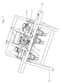
- Figur 1
- eine perspektivische Gesamtansicht einer erfindungsgemäßen Vorrichtung
Beidseitig des Transporteurs 2 sind innerhalb des Gestells 1 weitere Mittel zum gezielten Transport der Flaschen vorgesehen. Diese Mittel gliedern sich im wesentlichen in zwei Baugruppen welche jeweils an einer Seite des Transporteurs an jeweils einem Träger 8 angeordnet sind. Wesentlicher Bestandteil der Baugruppen sind die vorgesehenen Antriebsmotoren 3. Dabei sind, um eine komfortable Steuerung und Leistungsanpassung der Vorrichtung zu ermöglichen, Servomotoren vorgesehen. In weiteren zweckmäßigen Ausbildungen der Erfindung können auch andere sinnvolle Kombinationen von Motoren und Steuerungseinrichtungen vorgesehen sein. Durch diese Antriebsmotoren 3 werden anhand von Zahnriemenscheiben 4 zugehörige Zahnriemen 6 angetrieben, welche durch Umlenkrollen 5 so geführt werden, dass sie im wesentlichen parallel zur Transportrichtung des Transporteurs ausgerichtet sind. In einer besonders vorteilhaften Ausführungsform der Vorrichtung sind die Umlenkrollen 5 derart angeordnet, dass die Zahnriemen, in Transportrichtung gesehen, zunächst einen Einlauftrichter bilden, welcher die Flaschen sicher in die Behandlungszone führt, und dass sie dann in einen Bereich mit parallel angeordneten Zahnriemen 6 übergehen. Im Anschluss an den parallelen Teil ist vorgesehen, dass die Zahnriemen 6 einen Auslauftrichter bilden, welcher die Flaschen aus der Führung durch die Zahnriemen entlässt und sie wieder dem Transporteur 2 übergibt.
Claims (8)
- Vorrichtung zur Entfernung von geöffneten, an Flaschenschraubverschlüssen befindlichen Sicherungsringen bei Flaschen mit geöffneten und wiedermontierten Flaschenschraubverschlüssen dadurch gekennzeichnet, dass über Antriebsmotoren (3) angetriebene Mittel (4,5,6,7) Flaschen durch einen Behandlungsbereich führen und dass diese Flaschen dabei so an einer Schneidvorrichtung (9,10,11) vorbeigeführt werden, dass die geöffneten Sicherungsringe entfernt werden.
- Vorrichtung nach Anspruch 1 dadurch gekennzeichnet, dass die Mittel (4,5,6,7) zum Transport der Flaschen motorisch angetriebene Zahnriemen (6) beinhalten.
- Vorrichtung nach einem der Ansprüche 1 und 2, dadurch gekennzeichnet, dass die Antriebsmotoren (3) zum Antrieb der Zahnriemen (6) Servomotoren sind.
- Vorrichtung nach einem der Ansprüche 1 bis 3, dadurch gekennzeichnet, dass die Mittel (4,5,6,7) zum Transport der Flaschen zumindest einseitig an einem Transporteur (2) angeordnet sind.
- Vorrichtung nach einem der Ansprüche 1 bis 4, dadurch gekennzeichnet, dass die Zahnriemen (6) einen Einlauftrichter, einen parallelen Bereich und einen Auslauftrichter bilden.
- Vorrichtung nach einem der Ansprüche 1bis 5, dadurch gekennzeichnet, dass die Zahnriemen (6) zumindest im parallelen Bereich wenigstens einseitig zweispurig ausgebildet sind.
- Vorrichtung nach einem der Ansprüche 1 bis 6, dadurch gekennzeichnet, dass auf einer Seite des Transporteurs (2) die zweispurigen Zahnriemen durch eine Abrollplatte (7) ersetzt sind.
- Vorrichtung nach einem der Ansprüche 1 bis 7, dadurch gekennzeichnet, dass die Parameter Riemengeschwindigkeit und Laufrichtung jedes Zahnriemenantriebes separat steuerbar sind.
Applications Claiming Priority (2)
| Application Number | Priority Date | Filing Date | Title |
|---|---|---|---|
| DE20206793U DE20206793U1 (de) | 2002-04-29 | 2002-04-29 | Vorrichtung zur Entfernung von geöffneten, an Flaschenschraubverschlüssen befinldichen Sicherungsringen bei Flaschen |
| DE20206793U | 2002-04-29 |
Publications (2)
| Publication Number | Publication Date |
|---|---|
| EP1359114A1 true EP1359114A1 (de) | 2003-11-05 |
| EP1359114B1 EP1359114B1 (de) | 2005-12-14 |
Family
ID=7970664
Family Applications (1)
| Application Number | Title | Priority Date | Filing Date |
|---|---|---|---|
| EP20030004412 Expired - Lifetime EP1359114B1 (de) | 2002-04-29 | 2003-02-27 | Vorrichtung zur Entfernung von geöffneten, an Flaschenschraubverschlüssen befindlichen Sicherungringen bei Flaschen |
Country Status (3)
| Country | Link |
|---|---|
| EP (1) | EP1359114B1 (de) |
| DE (2) | DE20206793U1 (de) |
| DK (1) | DK1359114T3 (de) |
Cited By (1)
| Publication number | Priority date | Publication date | Assignee | Title |
|---|---|---|---|---|
| DE102004055963A1 (de) * | 2004-11-19 | 2006-05-24 | Krones Ag | Vorrichtung zum Behandeln von Flaschen |
Families Citing this family (1)
| Publication number | Priority date | Publication date | Assignee | Title |
|---|---|---|---|---|
| CN105967125B (zh) * | 2016-05-16 | 2018-07-06 | 广州达意隆包装机械股份有限公司 | 一种拔盖旋盖装置 |
Citations (6)
| Publication number | Priority date | Publication date | Assignee | Title |
|---|---|---|---|---|
| US1863338A (en) * | 1929-04-06 | 1932-06-14 | Hoffman Beverage Company | Foil remover |
| US3213725A (en) * | 1963-03-16 | 1965-10-26 | Settembrini Antoine Henri Di | Device for cutting off packaging, more particularly of plastic material |
| US3736660A (en) * | 1970-06-05 | 1973-06-05 | Alusuisse | Device for the opening of foil sealed containers |
| DE2729980B1 (de) | 1977-07-02 | 1978-11-09 | Alcoa Deutschland Gmbh Maschb | Verfahren zur Entfernung des Sicherungsringes eines Verschlusses aus Metall oder Kunststoff von Flaschen und Vorrichtung zur Durchfuehrung des Verfahrens |
| DE3209805A1 (de) | 1982-03-18 | 1983-09-29 | Grässle Maschinenbau, 7537 Remchingen | Verfahren und vorrichtung zum entfernen der sicherungsringe bei flaschen mit schraubverschluss |
| DE3905592C1 (en) * | 1989-02-23 | 1990-03-08 | Graessle Maschinenbau, 7537 Remchingen, De | Device for opening bent lever closures, especially on bottles |
Family Cites Families (3)
| Publication number | Priority date | Publication date | Assignee | Title |
|---|---|---|---|---|
| DE368081C (de) | 1920-09-30 | 1923-01-30 | Hubert Harz | Flaschenschabemaschine mit umlaufenden und federnden, an die Flasche anliegenden Schabern |
| DE2941888A1 (de) | 1979-10-17 | 1981-04-30 | Walter 7537 Remschingen Grässle | Greiferkopf fuer die automatische entfernung von sicherungsringen an flaschen |
| US4572033A (en) | 1985-04-19 | 1986-02-25 | Miller Brewing Company | Bottle decapper |
-
2002
- 2002-04-29 DE DE20206793U patent/DE20206793U1/de not_active Expired - Lifetime
-
2003
- 2003-02-27 DK DK03004412T patent/DK1359114T3/da active
- 2003-02-27 DE DE50301892T patent/DE50301892D1/de not_active Expired - Lifetime
- 2003-02-27 EP EP20030004412 patent/EP1359114B1/de not_active Expired - Lifetime
Patent Citations (6)
| Publication number | Priority date | Publication date | Assignee | Title |
|---|---|---|---|---|
| US1863338A (en) * | 1929-04-06 | 1932-06-14 | Hoffman Beverage Company | Foil remover |
| US3213725A (en) * | 1963-03-16 | 1965-10-26 | Settembrini Antoine Henri Di | Device for cutting off packaging, more particularly of plastic material |
| US3736660A (en) * | 1970-06-05 | 1973-06-05 | Alusuisse | Device for the opening of foil sealed containers |
| DE2729980B1 (de) | 1977-07-02 | 1978-11-09 | Alcoa Deutschland Gmbh Maschb | Verfahren zur Entfernung des Sicherungsringes eines Verschlusses aus Metall oder Kunststoff von Flaschen und Vorrichtung zur Durchfuehrung des Verfahrens |
| DE3209805A1 (de) | 1982-03-18 | 1983-09-29 | Grässle Maschinenbau, 7537 Remchingen | Verfahren und vorrichtung zum entfernen der sicherungsringe bei flaschen mit schraubverschluss |
| DE3905592C1 (en) * | 1989-02-23 | 1990-03-08 | Graessle Maschinenbau, 7537 Remchingen, De | Device for opening bent lever closures, especially on bottles |
Cited By (2)
| Publication number | Priority date | Publication date | Assignee | Title |
|---|---|---|---|---|
| DE102004055963A1 (de) * | 2004-11-19 | 2006-05-24 | Krones Ag | Vorrichtung zum Behandeln von Flaschen |
| EP1659089A1 (de) * | 2004-11-19 | 2006-05-24 | Krones AG | Vorrichtung zum Behandeln von Flaschen |
Also Published As
| Publication number | Publication date |
|---|---|
| DK1359114T3 (da) | 2006-02-06 |
| DE50301892D1 (de) | 2006-01-19 |
| EP1359114B1 (de) | 2005-12-14 |
| DE20206793U1 (de) | 2002-07-18 |
Similar Documents
| Publication | Publication Date | Title |
|---|---|---|
| DE602004011057T2 (de) | Sortiervorrichtung | |
| DE60114777T2 (de) | Vorrichtung zur übergabe von behältern mit einem führungsrad variabler geometrie | |
| EP0485937B1 (de) | Gruppiereinrichtung | |
| DE3124032C1 (de) | Behandlungsmaschine fuer Gegenstaende,insbesondere Etikettiermaschine oder Fueller fuer Behaelter,wie Flaschen | |
| DE3441850A1 (de) | Vorrichtung zum aufschrauben eines deckels auf eine behaelteroeffnung | |
| DE2641370C2 (de) | Gerät zum Vernichten von Mikrofilmen und dergleichen | |
| DE102012104213B4 (de) | Transportsystem für Behandlungsmaschinen sowie Behandlungsmaschine | |
| DE102014107427B4 (de) | Vorrichtung und Verfahren zum gesteuerten Ausrichten und/oder gesteuerten Drehen von Behältern | |
| AT510504A1 (de) | Verfahren und vorrichtung zum entfernen von an gefässen oder behältern anhaftenden teilen | |
| DE2360201A1 (de) | Vorrichtung zum entleeren von wegwerfbehaeltnissen, insbesondere zaehlflaeschchen fuer radioaktive fluessigkeiten | |
| DE102020126782C5 (de) | Applikationseinheit, Verfahren zum Betreiben einer Applikationseinheit sowie eine Verpackungsmaschine mit einer Applikationseinheit | |
| DE69214907T2 (de) | Vorrichtung und Verfahren zum Formen von Schwächungseinschnitten, insbesondere auf Behälterkappen | |
| EP0799580B1 (de) | Schälmaschine | |
| DE10015763A1 (de) | Vorrichtung zum Öffnen von Kunststofflaschen durch Abschneiden des Domes | |
| DE69018315T2 (de) | Vorrichtung zum Verdrehen von Bandmaterial in Schrauben- oder andere geeignete Form. | |
| EP1359114B1 (de) | Vorrichtung zur Entfernung von geöffneten, an Flaschenschraubverschlüssen befindlichen Sicherungringen bei Flaschen | |
| DE4034930A1 (de) | Vorrichtung zum ausrichten von teilen | |
| EP1710158B1 (de) | Verfahren und Vorrichtung zum Behandeln von Behältern | |
| DE4419323A1 (de) | Verfahren und Vorrichtung zum Aufschrauben von Verschlüssen auf Behälter | |
| DE19845836A1 (de) | Vorrichtung zum Verteilen von Stückgut auf mehrere weiterführende Förderbahnen | |
| DE3504303C2 (de) | ||
| DE69733431T2 (de) | Förderanlage zum fördern von behältern, insbesondere flaschen, durch mehrere arbeitsstationen | |
| DE7836568U1 (de) | Vorrichtung zur kontinuierlichen behandlung von dem umfang eines karussells o.dgl. zugefuehrten gegenstaenden, insbesondere flaschen | |
| EP2396257B1 (de) | Verstellvorrichtung zur verwendung bei einem transporteur | |
| DE3913294C2 (de) | Vorrichtung zum Fräsen von Unrundprofilen |
Legal Events
| Date | Code | Title | Description |
|---|---|---|---|
| PUAI | Public reference made under article 153(3) epc to a published international application that has entered the european phase |
Free format text: ORIGINAL CODE: 0009012 |
|
| AK | Designated contracting states |
Kind code of ref document: A1 Designated state(s): AT BE BG CH CY CZ DE DK EE ES FI FR GB GR HU IE IT LI LU MC NL PT SE SI SK TR |
|
| AX | Request for extension of the european patent |
Extension state: AL LT LV MK RO |
|
| 17P | Request for examination filed |
Effective date: 20031212 |
|
| AKX | Designation fees paid |
Designated state(s): DE DK FR GB IT SE |
|
| GRAP | Despatch of communication of intention to grant a patent |
Free format text: ORIGINAL CODE: EPIDOSNIGR1 |
|
| GRAS | Grant fee paid |
Free format text: ORIGINAL CODE: EPIDOSNIGR3 |
|
| GRAA | (expected) grant |
Free format text: ORIGINAL CODE: 0009210 |
|
| AK | Designated contracting states |
Kind code of ref document: B1 Designated state(s): DE DK FR GB IT SE |
|
| REG | Reference to a national code |
Ref country code: GB Ref legal event code: FG4D Free format text: NOT ENGLISH |
|
| REG | Reference to a national code |
Ref country code: SE Ref legal event code: TRGR |
|
| REF | Corresponds to: |
Ref document number: 50301892 Country of ref document: DE Date of ref document: 20060119 Kind code of ref document: P |
|
| REG | Reference to a national code |
Ref country code: DK Ref legal event code: T3 |
|
| GBT | Gb: translation of ep patent filed (gb section 77(6)(a)/1977) |
Effective date: 20060309 |
|
| RAP2 | Party data changed (patent owner data changed or rights of a patent transferred) |
Owner name: KHS AG |
|
| ET | Fr: translation filed | ||
| PLBE | No opposition filed within time limit |
Free format text: ORIGINAL CODE: 0009261 |
|
| STAA | Information on the status of an ep patent application or granted ep patent |
Free format text: STATUS: NO OPPOSITION FILED WITHIN TIME LIMIT |
|
| 26N | No opposition filed |
Effective date: 20060915 |
|
| PGFP | Annual fee paid to national office [announced via postgrant information from national office to epo] |
Ref country code: DK Payment date: 20100210 Year of fee payment: 8 |
|
| PGFP | Annual fee paid to national office [announced via postgrant information from national office to epo] |
Ref country code: FR Payment date: 20100226 Year of fee payment: 8 Ref country code: IT Payment date: 20100225 Year of fee payment: 8 |
|
| PGFP | Annual fee paid to national office [announced via postgrant information from national office to epo] |
Ref country code: DE Payment date: 20100219 Year of fee payment: 8 Ref country code: GB Payment date: 20100218 Year of fee payment: 8 |
|
| PGFP | Annual fee paid to national office [announced via postgrant information from national office to epo] |
Ref country code: SE Payment date: 20100212 Year of fee payment: 8 |
|
| REG | Reference to a national code |
Ref country code: DK Ref legal event code: EBP |
|
| REG | Reference to a national code |
Ref country code: SE Ref legal event code: EUG |
|
| GBPC | Gb: european patent ceased through non-payment of renewal fee |
Effective date: 20110227 |
|
| REG | Reference to a national code |
Ref country code: FR Ref legal event code: ST Effective date: 20111102 |
|
| PG25 | Lapsed in a contracting state [announced via postgrant information from national office to epo] |
Ref country code: IT Free format text: LAPSE BECAUSE OF NON-PAYMENT OF DUE FEES Effective date: 20110227 |
|
| REG | Reference to a national code |
Ref country code: DE Ref legal event code: R119 Ref document number: 50301892 Country of ref document: DE Effective date: 20110901 |
|
| PG25 | Lapsed in a contracting state [announced via postgrant information from national office to epo] |
Ref country code: FR Free format text: LAPSE BECAUSE OF NON-PAYMENT OF DUE FEES Effective date: 20110228 |
|
| PG25 | Lapsed in a contracting state [announced via postgrant information from national office to epo] |
Ref country code: GB Free format text: LAPSE BECAUSE OF NON-PAYMENT OF DUE FEES Effective date: 20110227 |
|
| PG25 | Lapsed in a contracting state [announced via postgrant information from national office to epo] |
Ref country code: SE Free format text: LAPSE BECAUSE OF NON-PAYMENT OF DUE FEES Effective date: 20110228 |
|
| PG25 | Lapsed in a contracting state [announced via postgrant information from national office to epo] |
Ref country code: DE Free format text: LAPSE BECAUSE OF NON-PAYMENT OF DUE FEES Effective date: 20110901 |