EP1358999A1 - Spleissvorrichtung - Google Patents
Spleissvorrichtung Download PDFInfo
- Publication number
- EP1358999A1 EP1358999A1 EP03005288A EP03005288A EP1358999A1 EP 1358999 A1 EP1358999 A1 EP 1358999A1 EP 03005288 A EP03005288 A EP 03005288A EP 03005288 A EP03005288 A EP 03005288A EP 1358999 A1 EP1358999 A1 EP 1358999A1
- Authority
- EP
- European Patent Office
- Prior art keywords
- strips
- bars
- teeth
- splice
- splicing
- Prior art date
- Legal status (The legal status is an assumption and is not a legal conclusion. Google has not performed a legal analysis and makes no representation as to the accuracy of the status listed.)
- Granted
Links
Images


Classifications
-
- B—PERFORMING OPERATIONS; TRANSPORTING
- B29—WORKING OF PLASTICS; WORKING OF SUBSTANCES IN A PLASTIC STATE IN GENERAL
- B29D—PRODUCING PARTICULAR ARTICLES FROM PLASTICS OR FROM SUBSTANCES IN A PLASTIC STATE
- B29D30/00—Producing pneumatic or solid tyres or parts thereof
- B29D30/06—Pneumatic tyres or parts thereof (e.g. produced by casting, moulding, compression moulding, injection moulding, centrifugal casting)
- B29D30/38—Textile inserts, e.g. cord or canvas layers, for tyres; Treatment of inserts prior to building the tyre
- B29D30/42—Endless textile bands without bead-rings
-
- B—PERFORMING OPERATIONS; TRANSPORTING
- B29—WORKING OF PLASTICS; WORKING OF SUBSTANCES IN A PLASTIC STATE IN GENERAL
- B29C—SHAPING OR JOINING OF PLASTICS; SHAPING OF MATERIAL IN A PLASTIC STATE, NOT OTHERWISE PROVIDED FOR; AFTER-TREATMENT OF THE SHAPED PRODUCTS, e.g. REPAIRING
- B29C65/00—Joining or sealing of preformed parts, e.g. welding of plastics materials; Apparatus therefor
-
- B—PERFORMING OPERATIONS; TRANSPORTING
- B29—WORKING OF PLASTICS; WORKING OF SUBSTANCES IN A PLASTIC STATE IN GENERAL
- B29C—SHAPING OR JOINING OF PLASTICS; SHAPING OF MATERIAL IN A PLASTIC STATE, NOT OTHERWISE PROVIDED FOR; AFTER-TREATMENT OF THE SHAPED PRODUCTS, e.g. REPAIRING
- B29C66/00—General aspects of processes or apparatus for joining preformed parts
- B29C66/01—General aspects dealing with the joint area or with the area to be joined
- B29C66/05—Particular design of joint configurations
- B29C66/10—Particular design of joint configurations particular design of the joint cross-sections
- B29C66/11—Joint cross-sections comprising a single joint-segment, i.e. one of the parts to be joined comprising a single joint-segment in the joint cross-section
- B29C66/114—Single butt joints
- B29C66/1142—Single butt to butt joints
-
- B—PERFORMING OPERATIONS; TRANSPORTING
- B29—WORKING OF PLASTICS; WORKING OF SUBSTANCES IN A PLASTIC STATE IN GENERAL
- B29C—SHAPING OR JOINING OF PLASTICS; SHAPING OF MATERIAL IN A PLASTIC STATE, NOT OTHERWISE PROVIDED FOR; AFTER-TREATMENT OF THE SHAPED PRODUCTS, e.g. REPAIRING
- B29C66/00—General aspects of processes or apparatus for joining preformed parts
- B29C66/40—General aspects of joining substantially flat articles, e.g. plates, sheets or web-like materials; Making flat seams in tubular or hollow articles; Joining single elements to substantially flat surfaces
- B29C66/41—Joining substantially flat articles ; Making flat seams in tubular or hollow articles
- B29C66/43—Joining a relatively small portion of the surface of said articles
-
- B—PERFORMING OPERATIONS; TRANSPORTING
- B29—WORKING OF PLASTICS; WORKING OF SUBSTANCES IN A PLASTIC STATE IN GENERAL
- B29D—PRODUCING PARTICULAR ARTICLES FROM PLASTICS OR FROM SUBSTANCES IN A PLASTIC STATE
- B29D30/00—Producing pneumatic or solid tyres or parts thereof
- B29D30/06—Pneumatic tyres or parts thereof (e.g. produced by casting, moulding, compression moulding, injection moulding, centrifugal casting)
- B29D30/38—Textile inserts, e.g. cord or canvas layers, for tyres; Treatment of inserts prior to building the tyre
- B29D30/42—Endless textile bands without bead-rings
- B29D2030/421—General aspects of the joining methods and devices for creating the bands
- B29D2030/422—Butt joining
-
- B—PERFORMING OPERATIONS; TRANSPORTING
- B29—WORKING OF PLASTICS; WORKING OF SUBSTANCES IN A PLASTIC STATE IN GENERAL
- B29K—INDEXING SCHEME ASSOCIATED WITH SUBCLASSES B29B, B29C OR B29D, RELATING TO MOULDING MATERIALS OR TO MATERIALS FOR MOULDS, REINFORCEMENTS, FILLERS OR PREFORMED PARTS, e.g. INSERTS
- B29K2021/00—Use of unspecified rubbers as moulding material
-
- B—PERFORMING OPERATIONS; TRANSPORTING
- B29—WORKING OF PLASTICS; WORKING OF SUBSTANCES IN A PLASTIC STATE IN GENERAL
- B29L—INDEXING SCHEME ASSOCIATED WITH SUBCLASS B29C, RELATING TO PARTICULAR ARTICLES
- B29L2030/00—Pneumatic or solid tyres or parts thereof
- B29L2030/003—Plies; Breakers
Definitions
- the invention relates to a splicing device for blunt splicing two tape sections, in particular uncured or pre-vulcanized cord tape sections for tire production, with two pairs of splice strips that can be moved against each other, whose superimposed individual splice strips between one upper release position and a lower clamping position for the edges of the Belt sections are movable.
- the invention is therefore based on the object of a splicing device at the outset mentioned type so that similar to bevel gear splicing devices an upward deflection of the band material and the formation is excluded from disruptive beads.
- the invention provides that the splice strips Toothed strips are, the teeth of the top two and those of the two lower toothed ridges placed against each other and staggered are.
- the teeth complementary to the gaps are trapezoidal, in practice the teeth never fully interlock during the splicing process, as the interlocking is stopped by the solidification of the material during the splicing process.
- the lower splice strips only one of which can be moved horizontally against the other should be stored are vertically immovable immediately below the Transport plane of the band sections to be spliced arranged and preferred on a fixed table, while the upper ones on a lowerable support plate are adjustable against each other.
- the splicer 1 shown which is between a material feed belt 2 and a material conveyor belt 3 is arranged, consists of two rigid a lower work table 4 mounted lower splice strips 5a and 6a and two mounted together on a plate 7, lifting and lifting via a pneumatic cylinder 8 lowerable splice strips 5b and 6b.
- the splice strips 5a and 5b are each rigidly attached to the table 4 or the support plate 7, while the splice strips 6a and 6b can be moved horizontally against the fixed splice strips 5a and 5b are.
- the process is carried out using a single-stage hydraulic piston 9 and 10, which is supplied with compressed air via a connecting piece 11 and 12.
- the pistons 9 and 10 work against springs, not shown, between the splice strips 5a and 6a on the one hand and 5b and 6b on the other hand.
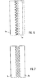
- the essential peculiarity of the splicing device according to the invention is in that the four splice strips 5a, 5b, 6a and 6b are designed as toothed racks are, the teeth 13 and 14 toothed strips in the illustrated embodiment are trapezoidal and complementary to the shape of the tooth gap 14.
- the racks 5a, 6a on the one hand, 6b and 5b on the other hand are in the longitudinal direction so offset that their teeth, as can be seen in particular in FIGS. 4 and 6 can see, are staggered.
- Fig. 2 you can see the incoming band section 15, the one with the outgoing Band section 16 is to be spliced.
- the plate 7 runs with the upper splice strips 5b and 6b down and clamps the two band sections 15 and 16 directly up to the respective band section edge 17 or 18.
- the right-hand splice strips 6a and 6b using the pistons 9 and 10 move horizontally, bringing the edges 17 and 18 together be pressed.
- the interlocking of the teeth 13 it is prevented that the band material bulges out and forms a bulge on the splice seam can.
- Fig. 6 you can see this very well by the interlocking teeth the splice strips 5a and 6a.
Landscapes
- Engineering & Computer Science (AREA)
- Mechanical Engineering (AREA)
- Textile Engineering (AREA)
- Tyre Moulding (AREA)
Abstract
Description
- Fig. 1
- eine Übersichtsskizze einer erfindungsgemäßen Spleißvorrichtung,
- Fig. 2
- eine vergrößerte Stirnansicht der Spleißleisten in der auseinander gefahrenen Ausgangsstellung,
- Fig. 3
- eine Draufsicht auf die unteren oder oberen Zahnleisten in der Ausgangsstellung nach Fig. 2,
- Fig. 4
- eine der Fig. 2 entsprechende Stirnansicht nach dem Herunterfahren der oberen Spleißleisten zum Einklemmen der Bandabschnitte,
- Fig. 5
- eine der Fig. 4 entsprechende Ansicht nach dem horizontalen Zusammenfahren der Spleißleisten zum Verbinden der Bandabschnitte,
- Fig. 6
- eine Draufsicht auf die Zahnstangen in der Betriebsstellung nach Fig. 5 nach dem Verspleißen und
- Fig. 7
- eine Draufsicht auf die Spleißleisten, wobei sowohl die oberen als auch die unteren Spleißleisten in ihrer Versetzung auf Lücke dargestellt sind.
Claims (6)
- Spleißvorrichtung zum stumpfen Verspleißen zweier Bandabschnitte, insbesondere un- oder vorvulkanisierter Cordbandabschnitte zur Reifenherstellung, mit zwei gegeneinander verschiebbaren Spleißleistenpaaren, deren übereinander liegende Einzelspleißleisten zwischen einer oberen Freigabestellung und einer unteren Einklemmstellung für die Ränder der Bandabschnitte verfahrbar sind, dadurch gekennzeichnet, dass die Spleißleisten (5a, 5b, 6a, 6b) Zahnleisten sind, wobei die Zähne (13) der beiden oberen und die beiden unteren Zahnleisten (5b, 6b) und die der beiden unteren Zahnleisten (5a, 6a) gegeneinander gestellt und auf Lücke versetzt angeordnet sind.
- Spleißvorrichtung nach Anspruch 1, dadurch gekennzeichnet, dass die Zähne (13) komplementär zu den Lücken (14) trapezförmig ausgebildet sind.
- Spleißvorrichtung nach Anspruch 1 oder 2, dadurch gekennzeichnet, dass die Zähne (13) der übereinander liegenden Zahnstangen (5a, 5b; 6a, 6b) auf Lücke versetzt angeordnet sind.
- Spleißvorrichtung nach einem der Ansprüche 1 bis 3, dadurch gekennzeichnet, dass die unteren Spleißleisten (5a, 6a) von denen nur eine (6a) horizontal gegen die andere verschiebbar gelagert ist, vertikal unverschiebbar unter der Transportebene der zu verspleißenden Bandabschnitte (15, 16) angeordnet sind.
- Spleißvorrichtung nach einem der Ansprüche 1 bis 4, dadurch gekennzeichnet, dass die horizontale Bewegung der Spleißleisten (6a, 6b) durch einstufige, gegen die Wirkung von Abstützfedern zwischen den Spleißleisten (5a, 6a; 5b, 6b) arbeitende, Hydraulik- oder Pneumatikzylinder (9, 10) erfolgt.
- Spleißvorrichtung nach einem der Ansprüche 1 bis 5, dadurch gekennzeichnet, dass die unteren Spleißleisten (5a, 6a) an einem festen Tisch (4) und die oberen an einer absenkbaren Tragplatte (7) (gegeneinander verstellbar) gelagert sind.
Applications Claiming Priority (2)
| Application Number | Priority Date | Filing Date | Title |
|---|---|---|---|
| DE10219928 | 2002-05-03 | ||
| DE10219928A DE10219928B4 (de) | 2002-05-03 | 2002-05-03 | Spleißvorrichtung |
Publications (2)
| Publication Number | Publication Date |
|---|---|
| EP1358999A1 true EP1358999A1 (de) | 2003-11-05 |
| EP1358999B1 EP1358999B1 (de) | 2008-07-16 |
Family
ID=28798996
Family Applications (1)
| Application Number | Title | Priority Date | Filing Date |
|---|---|---|---|
| EP03005288A Expired - Lifetime EP1358999B1 (de) | 2002-05-03 | 2003-03-11 | Spleissvorrichtung |
Country Status (2)
| Country | Link |
|---|---|
| EP (1) | EP1358999B1 (de) |
| DE (2) | DE10219928B4 (de) |
Cited By (6)
| Publication number | Priority date | Publication date | Assignee | Title |
|---|---|---|---|---|
| JP2004203041A (ja) * | 2002-12-20 | 2004-07-22 | Goodyear Tire & Rubber Co:The | タイヤの準備プライの製造装置および製造方法 |
| JP2006142828A (ja) * | 2004-11-17 | 2006-06-08 | Karl Eugen Fischer Gmbh Maschinenfabrik | 二つのバンド片の突合せつなぎのためのつなぎ装置 |
| WO2006125491A1 (de) * | 2005-05-24 | 2006-11-30 | Continental Aktiengesellschaft | Verfahren und vorrichtung einsetzbar im automatisiert ablaufenden aufbau eines fahrzeugluftreifens |
| EP1731294A1 (de) | 2005-06-06 | 2006-12-13 | Shigemasa Takagi | Spleissvorrichtung für Kautschukbahn und Verfahren zum Spleissen |
| EP1798020A3 (de) * | 2005-12-14 | 2007-08-01 | Karl Eugen Fischer GmbH Maschinenfabrik | Spleisseinrichtung |
| EP3002116A1 (de) * | 2014-10-01 | 2016-04-06 | Karl Eugen Fischer GmbH | Spleissvorrichtung zum stumpfspleissen eines klebrigen bandes |
Citations (5)
| Publication number | Priority date | Publication date | Assignee | Title |
|---|---|---|---|---|
| US3100731A (en) * | 1959-03-18 | 1963-08-13 | Firestone Tire & Rubber Co | Method and apparatus for joining sheet material |
| GB1114024A (en) * | 1965-08-27 | 1968-05-15 | Continental Gummi Werke Ag | Improvements in and relating to the joining of webs |
| GB1376400A (en) * | 1971-09-09 | 1974-12-04 | Continental Gummi Werke Ag | Apparatus for joining together the ends of plastics or plastically- resilient webs |
| US4054475A (en) * | 1973-07-03 | 1977-10-18 | Industrie Pirelli S.P.A. | Method for producing a continuous band of rubberized fabric having transversal reinforcing metal elements |
| US4173509A (en) * | 1976-01-15 | 1979-11-06 | Bandag Incorporated | Apparatus for splicing tread strips |
-
2002
- 2002-05-03 DE DE10219928A patent/DE10219928B4/de not_active Expired - Lifetime
-
2003
- 2003-03-11 DE DE50310141T patent/DE50310141D1/de not_active Expired - Lifetime
- 2003-03-11 EP EP03005288A patent/EP1358999B1/de not_active Expired - Lifetime
Patent Citations (5)
| Publication number | Priority date | Publication date | Assignee | Title |
|---|---|---|---|---|
| US3100731A (en) * | 1959-03-18 | 1963-08-13 | Firestone Tire & Rubber Co | Method and apparatus for joining sheet material |
| GB1114024A (en) * | 1965-08-27 | 1968-05-15 | Continental Gummi Werke Ag | Improvements in and relating to the joining of webs |
| GB1376400A (en) * | 1971-09-09 | 1974-12-04 | Continental Gummi Werke Ag | Apparatus for joining together the ends of plastics or plastically- resilient webs |
| US4054475A (en) * | 1973-07-03 | 1977-10-18 | Industrie Pirelli S.P.A. | Method for producing a continuous band of rubberized fabric having transversal reinforcing metal elements |
| US4173509A (en) * | 1976-01-15 | 1979-11-06 | Bandag Incorporated | Apparatus for splicing tread strips |
Cited By (15)
| Publication number | Priority date | Publication date | Assignee | Title |
|---|---|---|---|---|
| EP1431023A3 (de) * | 2002-12-20 | 2005-07-13 | The Goodyear Tire & Rubber Company | Verfahren und Vorrichtung zur Herstellung einer Reifenlage |
| US7073552B2 (en) | 2002-12-20 | 2006-07-11 | The Goodyear Tire & Rubber Company | Tire preparation ply manufacturing apparatus and method |
| US8685199B2 (en) | 2002-12-20 | 2014-04-01 | The Goodyear Tire & Rubber Company | Tire preparation ply manufacturing apparatus and method |
| JP2004203041A (ja) * | 2002-12-20 | 2004-07-22 | Goodyear Tire & Rubber Co:The | タイヤの準備プライの製造装置および製造方法 |
| JP2006142828A (ja) * | 2004-11-17 | 2006-06-08 | Karl Eugen Fischer Gmbh Maschinenfabrik | 二つのバンド片の突合せつなぎのためのつなぎ装置 |
| JP2008542055A (ja) * | 2005-05-24 | 2008-11-27 | コンチネンタル アクチェンゲゼルシャフト | 車両タイヤの自動化組立で使用可能な方法及び装置 |
| WO2006125491A1 (de) * | 2005-05-24 | 2006-11-30 | Continental Aktiengesellschaft | Verfahren und vorrichtung einsetzbar im automatisiert ablaufenden aufbau eines fahrzeugluftreifens |
| US8540841B2 (en) | 2005-06-06 | 2013-09-24 | Fuji Shoji Co., Ltd. | Rubber sheet jointing apparatus and method |
| US8127817B2 (en) | 2005-06-06 | 2012-03-06 | Fuji Shoji Co., Ltd. | Rubber sheet jointing apparatus and method |
| EP1731294A1 (de) | 2005-06-06 | 2006-12-13 | Shigemasa Takagi | Spleissvorrichtung für Kautschukbahn und Verfahren zum Spleissen |
| CN1876354B (zh) * | 2005-06-06 | 2014-08-13 | 不二精工株式会社 | 橡胶板连接装置和方法 |
| EP1798020A3 (de) * | 2005-12-14 | 2007-08-01 | Karl Eugen Fischer GmbH Maschinenfabrik | Spleisseinrichtung |
| EP3002116A1 (de) * | 2014-10-01 | 2016-04-06 | Karl Eugen Fischer GmbH | Spleissvorrichtung zum stumpfspleissen eines klebrigen bandes |
| CN105751554A (zh) * | 2014-10-01 | 2016-07-13 | 卡尔欧根菲舍尔有限公司 | 用于对接发粘的带件的拼接装置 |
| CN105751554B (zh) * | 2014-10-01 | 2018-06-29 | 卡尔欧根菲舍尔有限公司 | 用于对接发粘的带件的拼接装置 |
Also Published As
| Publication number | Publication date |
|---|---|
| DE10219928B4 (de) | 2004-03-18 |
| DE50310141D1 (de) | 2008-08-28 |
| EP1358999B1 (de) | 2008-07-16 |
| DE10219928A1 (de) | 2003-11-20 |
Similar Documents
| Publication | Publication Date | Title |
|---|---|---|
| DE19732298C1 (de) | Vorrichtung und Verfahren zum Umhüllen eines Stapels | |
| DE69603273T2 (de) | Verfahren und vorrichtung zum komprimieren und verpackung von komprimierbaren produkten | |
| DE2640939C2 (de) | Blechband-Bund sowie Verfahren und Vorrichtung zu seiner Herstellung | |
| DE2437309A1 (de) | Halbstarre verpackung und maschine zum herstellen und flachen zusammenlegen derselben | |
| EP1871568B1 (de) | Schutzabdeckung mit stabilisierungselement | |
| EP1358999B1 (de) | Spleissvorrichtung | |
| DE2051779C3 (de) | Vorrichtung zum Beschneiden und anschließenden Verbinden der Enden einander folgenden Bänder | |
| DE102004055528B4 (de) | Spleißvorrichtung zum stumpfen Verspleißen zweier Bandabschnitte | |
| EP3885110B1 (de) | Verfahren zum verschweissen zweier sich überlappender und auf der oberseite eines gutstapels befindlicher folienabschnitte zum bilden einer umhüllung sowie vorrichtung zum verschweissen zweier sich überlappender und auf der oberseite eines gutstapels befindlicher folienabschnitte zum bilden einer umhüllung | |
| EP1356917B1 (de) | Vorrichtung zum Ausbilden und/oder Verschliessen einer Verpackungseinheit | |
| DE2434805A1 (de) | Einwickelmaschine zum herstellen von sammelpackungen | |
| EP0460681B1 (de) | Reff- und/oder Stretcheinrichtung für schlauchförmige Stretch-Umhüllungsfolie | |
| DE2301452A1 (de) | In der hoehe veraenderliche hubsaeule | |
| DE3402461C2 (de) | Vorrichtung zum Palettieren von Säcken, Kisten, Kartons und dgl. Stückgüter | |
| EP1644141B1 (de) | Einrichtung zur herstellung von ebenflächigem streckmaterial | |
| EP0183085A1 (de) | Vorrichtung zum Falten der Öffnungen von gefüllten Säcken | |
| DE2160292A1 (de) | Verfahren und Vorrichtung zur Anbringung einer Folien-Umhüllung um eine Anzahl zu einer Einheit zusammengestellter Körper | |
| DE1761372C3 (de) | Stanzwerkzeug | |
| EP3409435B1 (de) | Presseinrichtung für die herstellung von holzsträngen aus hölzern | |
| DE321499C (de) | Einrichtung zum Wellen von Papier, Pappe o. dgl. in der Laengsrichtung | |
| DE2545813A1 (de) | Vorrichtung zum verpacken flacher werkstuecke | |
| DE2228728A1 (de) | Vorrichtung zum stueckweisen austragen von walzgummifellen aus einer kuehlanlage | |
| DE2312689A1 (de) | Verfahren und vorrichtung zum transportieren von plattenmaterial | |
| DE966123C (de) | Pressformmaschine mit verfahrbarer Pressplatte | |
| DE2750392A1 (de) | Maschine zum herstellen von beuteln aus kunststoff |
Legal Events
| Date | Code | Title | Description |
|---|---|---|---|
| PUAI | Public reference made under article 153(3) epc to a published international application that has entered the european phase |
Free format text: ORIGINAL CODE: 0009012 |
|
| AK | Designated contracting states |
Kind code of ref document: A1 Designated state(s): AT BE BG CH CY CZ DE DK EE ES FI FR GB GR HU IE IT LI LU MC NL PT RO SE SI SK TR |
|
| AX | Request for extension of the european patent |
Extension state: AL LT LV MK |
|
| 17P | Request for examination filed |
Effective date: 20031212 |
|
| AKX | Designation fees paid |
Designated state(s): AT BE BG CH LI |
|
| RBV | Designated contracting states (corrected) |
Designated state(s): CZ DE NL SK |
|
| REG | Reference to a national code |
Ref country code: DE Ref legal event code: 8566 |
|
| 17Q | First examination report despatched |
Effective date: 20060420 |
|
| GRAP | Despatch of communication of intention to grant a patent |
Free format text: ORIGINAL CODE: EPIDOSNIGR1 |
|
| GRAS | Grant fee paid |
Free format text: ORIGINAL CODE: EPIDOSNIGR3 |
|
| GRAA | (expected) grant |
Free format text: ORIGINAL CODE: 0009210 |
|
| AK | Designated contracting states |
Kind code of ref document: B1 Designated state(s): CZ DE NL SK |
|
| REF | Corresponds to: |
Ref document number: 50310141 Country of ref document: DE Date of ref document: 20080828 Kind code of ref document: P |
|
| PLBE | No opposition filed within time limit |
Free format text: ORIGINAL CODE: 0009261 |
|
| STAA | Information on the status of an ep patent application or granted ep patent |
Free format text: STATUS: NO OPPOSITION FILED WITHIN TIME LIMIT |
|
| 26N | No opposition filed |
Effective date: 20090417 |
|
| PGFP | Annual fee paid to national office [announced via postgrant information from national office to epo] |
Ref country code: DE Payment date: 20220314 Year of fee payment: 20 |
|
| PGFP | Annual fee paid to national office [announced via postgrant information from national office to epo] |
Ref country code: SK Payment date: 20220301 Year of fee payment: 20 Ref country code: NL Payment date: 20220322 Year of fee payment: 20 Ref country code: CZ Payment date: 20220303 Year of fee payment: 20 |
|
| REG | Reference to a national code |
Ref country code: DE Ref legal event code: R071 Ref document number: 50310141 Country of ref document: DE |
|
| REG | Reference to a national code |
Ref country code: NL Ref legal event code: MK Effective date: 20230310 |
|
| REG | Reference to a national code |
Ref country code: SK Ref legal event code: MK4A Ref document number: E 4225 Country of ref document: SK Expiry date: 20230311 |
|
| PG25 | Lapsed in a contracting state [announced via postgrant information from national office to epo] |
Ref country code: CZ Free format text: LAPSE BECAUSE OF EXPIRATION OF PROTECTION Effective date: 20230311 |
|
| PG25 | Lapsed in a contracting state [announced via postgrant information from national office to epo] |
Ref country code: SK Free format text: LAPSE BECAUSE OF EXPIRATION OF PROTECTION Effective date: 20230311 |