EP1355324A1 - Poudre et composition conductrices - Google Patents
Poudre et composition conductrices Download PDFInfo
- Publication number
- EP1355324A1 EP1355324A1 EP01273565A EP01273565A EP1355324A1 EP 1355324 A1 EP1355324 A1 EP 1355324A1 EP 01273565 A EP01273565 A EP 01273565A EP 01273565 A EP01273565 A EP 01273565A EP 1355324 A1 EP1355324 A1 EP 1355324A1
- Authority
- EP
- European Patent Office
- Prior art keywords
- conductive
- convex
- powder
- resin
- conductive powder
- Prior art date
- Legal status (The legal status is an assumption and is not a legal conclusion. Google has not performed a legal analysis and makes no representation as to the accuracy of the status listed.)
- Withdrawn
Links
Images


Classifications
-
- H—ELECTRICITY
- H05—ELECTRIC TECHNIQUES NOT OTHERWISE PROVIDED FOR
- H05K—PRINTED CIRCUITS; CASINGS OR CONSTRUCTIONAL DETAILS OF ELECTRIC APPARATUS; MANUFACTURE OF ASSEMBLAGES OF ELECTRICAL COMPONENTS
- H05K1/00—Printed circuits
- H05K1/02—Details
- H05K1/09—Use of materials for the conductive, e.g. metallic pattern
- H05K1/092—Dispersed materials, e.g. conductive pastes or inks
- H05K1/095—Dispersed materials, e.g. conductive pastes or inks for polymer thick films, i.e. having a permanent organic polymeric binder
-
- B—PERFORMING OPERATIONS; TRANSPORTING
- B22—CASTING; POWDER METALLURGY
- B22F—WORKING METALLIC POWDER; MANUFACTURE OF ARTICLES FROM METALLIC POWDER; MAKING METALLIC POWDER; APPARATUS OR DEVICES SPECIALLY ADAPTED FOR METALLIC POWDER
- B22F1/00—Metallic powder; Treatment of metallic powder, e.g. to facilitate working or to improve properties
-
- H—ELECTRICITY
- H01—ELECTRIC ELEMENTS
- H01B—CABLES; CONDUCTORS; INSULATORS; SELECTION OF MATERIALS FOR THEIR CONDUCTIVE, INSULATING OR DIELECTRIC PROPERTIES
- H01B1/00—Conductors or conductive bodies characterised by the conductive materials; Selection of materials as conductors
- H01B1/20—Conductive material dispersed in non-conductive organic material
- H01B1/22—Conductive material dispersed in non-conductive organic material the conductive material comprising metals or alloys
-
- H—ELECTRICITY
- H01—ELECTRIC ELEMENTS
- H01R—ELECTRICALLY-CONDUCTIVE CONNECTIONS; STRUCTURAL ASSOCIATIONS OF A PLURALITY OF MUTUALLY-INSULATED ELECTRICAL CONNECTING ELEMENTS; COUPLING DEVICES; CURRENT COLLECTORS
- H01R13/00—Details of coupling devices of the kinds covered by groups H01R12/70 or H01R24/00 - H01R33/00
- H01R13/02—Contact members
- H01R13/03—Contact members characterised by the material, e.g. plating, or coating materials
-
- H—ELECTRICITY
- H01—ELECTRIC ELEMENTS
- H01R—ELECTRICALLY-CONDUCTIVE CONNECTIONS; STRUCTURAL ASSOCIATIONS OF A PLURALITY OF MUTUALLY-INSULATED ELECTRICAL CONNECTING ELEMENTS; COUPLING DEVICES; CURRENT COLLECTORS
- H01R4/00—Electrically-conductive connections between two or more conductive members in direct contact, i.e. touching one another; Means for effecting or maintaining such contact; Electrically-conductive connections having two or more spaced connecting locations for conductors and using contact members penetrating insulation
- H01R4/04—Electrically-conductive connections between two or more conductive members in direct contact, i.e. touching one another; Means for effecting or maintaining such contact; Electrically-conductive connections having two or more spaced connecting locations for conductors and using contact members penetrating insulation using electrically conductive adhesives
-
- B—PERFORMING OPERATIONS; TRANSPORTING
- B22—CASTING; POWDER METALLURGY
- B22F—WORKING METALLIC POWDER; MANUFACTURE OF ARTICLES FROM METALLIC POWDER; MAKING METALLIC POWDER; APPARATUS OR DEVICES SPECIALLY ADAPTED FOR METALLIC POWDER
- B22F2998/00—Supplementary information concerning processes or compositions relating to powder metallurgy
-
- B—PERFORMING OPERATIONS; TRANSPORTING
- B22—CASTING; POWDER METALLURGY
- B22F—WORKING METALLIC POWDER; MANUFACTURE OF ARTICLES FROM METALLIC POWDER; MAKING METALLIC POWDER; APPARATUS OR DEVICES SPECIALLY ADAPTED FOR METALLIC POWDER
- B22F2999/00—Aspects linked to processes or compositions used in powder metallurgy
-
- H—ELECTRICITY
- H05—ELECTRIC TECHNIQUES NOT OTHERWISE PROVIDED FOR
- H05K—PRINTED CIRCUITS; CASINGS OR CONSTRUCTIONAL DETAILS OF ELECTRIC APPARATUS; MANUFACTURE OF ASSEMBLAGES OF ELECTRICAL COMPONENTS
- H05K2203/00—Indexing scheme relating to apparatus or processes for manufacturing printed circuits covered by H05K3/00
- H05K2203/03—Metal processing
- H05K2203/0307—Providing micro- or nanometer scale roughness on a metal surface, e.g. by plating of nodules or dendrites
-
- H—ELECTRICITY
- H05—ELECTRIC TECHNIQUES NOT OTHERWISE PROVIDED FOR
- H05K—PRINTED CIRCUITS; CASINGS OR CONSTRUCTIONAL DETAILS OF ELECTRIC APPARATUS; MANUFACTURE OF ASSEMBLAGES OF ELECTRICAL COMPONENTS
- H05K3/00—Apparatus or processes for manufacturing printed circuits
- H05K3/30—Assembling printed circuits with electric components, e.g. with resistor
- H05K3/32—Assembling printed circuits with electric components, e.g. with resistor electrically connecting electric components or wires to printed circuits
- H05K3/321—Assembling printed circuits with electric components, e.g. with resistor electrically connecting electric components or wires to printed circuits by conductive adhesives
Definitions
- the present invention relates to a conductive powder and a conductive composition, and more particularly to a conductive powder for an electrical industry which can show the highly conductivity (low resistivity) even in condition that a resin is included, and a conductive composition using the same.
- a conductive composition constituted from the mixing of a definite amount of a metal powder into a resin, has been widely used in the paste for thick conductor, a conductive adhesive and the like.
- a reduced Ag powder made from the reduction reaction from silver nitrate by using the reducing agent such as hydrazine, formaldehyde, and ascorbic acid are known and disclosed in JP S63-179009A, JP H8-92611A, JP H8-92612A, JP H10-88206A, JP H10-88207A, JP 2000-1706A, JP 2000-1707A, JP 2000-129318A, JP 2000-239713, JP 2001-49309A and JP 2001-107101A.
- JP H5-156326A JP H10-183208A, JP H10-183209A and JP 2000-265202A, a fine non-aggregated Ag powder and a flake type Ag powder made from pyrolysis are disclosed.
- JP H5-81923A JP H7-109501A, and JP H11-350002A, a fine non-aggregated Ag powder and a flake type Ag powder made from grinding procedure are disclosed.
- JP H9-125110A a dendrite Ag powder made from electrolysis is disclosed.
- the conventional metal powders generally show the low conductivity in condition that a resin is included, and many metal powders are required into the resin to obtain the fixed conductive resistance between the conductive substrates. Therefore, there were the drawbacks that the viscosity of the conventional conductive composition becomes high and the handling-ability becomes worse. To improve the handling-ability, the adding quantity is restricted to be the low level and much diluent such as organic solvents are required.
- the electrical resistivity for the conductive composition obtained from mixing conductive powders is 1.4 ⁇ 10 - 3 ⁇ cm which is insufficient value.
- the table 1 shows the formulations of the conductive compositions before drying and after dry curing, that is the resin weight after dry curing was about 9 wt.% and Ag weight after dry curing was about 91 wt.%. Accordingly, estimated from the void value(45%) based on the assuming that the same spheres are filled per unit volume, the filing ratio of the resin was about 1/5.
- voids were observed in the conductive composition after drying curing by the optical microscope.
- voids are porous constitution, which are made from the low resin content or high conductive powder, and they are one of the reasons of the low conductive reliability.
- First embodiment of the present invention is directed to a conductive powder having a convex radically extended and a concave among the convex, having the following features;
- the first embodiment 1 it is necessary for the first embodiment 1 to have at least one feature among the above-mentioned 1 to 3 features to solve the conventional problems, but it is more favorable to have more than one feature to solve the conventional problems.
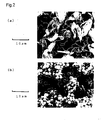
- the shape of the convex is favorable at least one shape selected from the group essentially consisting of a needle shape, a rod shape (including a pole shape or a bar shape) or a petal shape as illustratively shown in Fig.1(a), (b) and (c).
- the conductive composition including the combination of a Ag powder having the needle type convex, a Ag powder having the rod type convex and a Ag powder having the petal type convex shows the better electrical conductivity since an electrical path are easily formed. More concretely, the conductive composition including the combination of 10 to 50 wt.% of a Ag powder having the needle type convex, 15 to 50 wt.% of a Ag powder having the rod type convex and 20 to 50 wt.% of a Ag powder having the petal type convex based on the total 100% weight, can show the electrical conductivity of 5 ⁇ 10 -6 to 5 ⁇ 10 -5 ⁇ cm.
- the length of the convex is favorable to exceed 40 % of average radius of the sphere consisting of the closed aspect surrounded by tracing the tip of the convex.
- the average particle size of a Ag powder having a needle type convex as shown in Fig.1(a) is about 6 ⁇ m and the average length of such convex is 2.6 ⁇ m.
- the average particle size of a Ag powder having a rod type convex as shown in Fig.1(b) is about 11 ⁇ m and the average length of such convex is 3 ⁇ m.
- the average particle size of a Ag powder having a petal type convex as shown in Fig.1(c) is about 5 ⁇ m and the average length of such convex is 2 ⁇ m.
- Such Ag powder can secure the press-fitting to the concave and the electrical resistivity in condition that a resin is included becomes much lower and the mechanical stability of the contact area can be improved.
- the concave (sometimes called as dent) is favorable to be formed between the adjoining convex and to have the dent shape which can press-fit to the convex as illustratively shown in Fig.1(a), (b) and (c).
- the depth (length) of the concave can be expressed by the possessing volume in a conductive powder, namely a void of the concave in a conductive powder. More concretely, it is favorable that the void is to be set within a range of exceeding 40vol.% when the total volume of the expected sphere consisting of the closed carve line connecting the tips of the concave is 100 vol.%.
- the reason is that when the void is below 40vol.%, the press-fitting between the convex and concave may become insufficient. On the other hand, when the void is too big, the may be the case where mechanical strength of the conductive powder becomes low.
- the void is to be set within a range of 42 to 70 vol.% and further more favorable that the void is within a range of 45 to 60 vol.%.
- the average particle size of the Ag powder having the needle type concave as shown in Fig.1 (a) is 6 ⁇ m and its void is 54 vol.%.
- the average particle size of the Ag powder having the rod type concave as shown in Fig.1 (b) is 11 ⁇ m and its void is 49 vol.%.
- the average particle size of the Ag powder having the petal type concave as shown in Fig.1 (c) is 5 ⁇ m and its void is 47 vol.%.
- Such Ag powder can secure the press-fitting to the concave and the electrical resistivity in condition that a resin is included becomes much lower and the mechanical stability of the contact area can be improved.
- the average particle size of the conductive powder is set to a value, which is within a range of about 0.1 to 22 ⁇ m.
- the average particle size of the conductive powder assumes a value less than 0.1 ⁇ m, there arise a case that a large quantity of the conductive powder is required to obtain the good conductivity.
- the average particle size of the conductive powder exceeds 22 ⁇ m, there arises a case that the mixing and dispersion become difficult and the long making time is required.
- the average particle size of the conductive powder is more favorable to set the average particle size of the conductive powder to a value, which falls within a range of about 1 to 15 ⁇ m and it is further more favorable to set such an average particle size to a value, which falls within a range of about 3 to 10 ⁇ m.
- the average particle size of the conductive powder can be measured by using a laser-type particle counter, or directly computed by taking an image of the conductive powder into an optical microscope, or by computing the average particle diameter based on the image using an image processing apparatus.
- Such type of conductive powder a single type or a combination of two or more selected from a group consisting of Ag, Ni, Au, Cu, Al, Fe, Zr, Tw, Sn, Pb, Solder and the like.
- Ag or Ni is more favorable since they can ensure the favorable conductivity and can provide the relative cheap conductive powders. Also, Ag or Ni is easily dispersed in a resin, especially an epoxy resin or an acryl type resin.
- the reason is that applying the surface treatment can increase the mechanical strength of the convex of the conductive powder as well as the conductive powder itself, and the bending or the broken of the convex of the conductive powder can be easily protected.
- the thickness of plating is within a range of 0.01 to 3 ⁇ m in consideration of the plating effect and the like.
- the convex and the concave of the adjoining conductive powders are press-fitted by sliding movement easily to form the electrical path.
- Such surface treatment agent as favorable samples are illustrated as silicone oils, fluororesin type surface treatment agents and the several surfactants.
- the using quantity of the friction decreasing agent is set to be the value within a range of 0.1 to 30 pbw. based on 100 pbw. of the conductive powder, for example in consideration of the effects of the friction decreasing and the electrically insulating.
- the electrical resistivity of the conductive powder in condition that a resin is included is set to be the value within a range of 5 ⁇ 10 -6 to 1 ⁇ 10 -3 ⁇ cm.
- the electrical resistivity of the conductive resin in condition that a resin is included is set to be the value within a range of 5 ⁇ 10 -6 to 5 ⁇ 10 -4 ⁇ cm, and most favorable that the electrical resistivity is set to be the value within a range of 5 ⁇ 10 -6 to 1 ⁇ 10 - 4 ⁇ cm.
- the electrical resistivity of a conductive powder in condition a resin can be measured by the procedure later described in example 1.
- TCR Thermal coefficient of resistance
- thermal coefficient of resistance(TCR) of the conductive powder in condition that a resin is included is set to be the value within a range of 1 ⁇ 10 2 to 1 ⁇ 10 5 ppm/°C.
- TCR value when such TCR value is below 1 ⁇ 10 2 ppm/°C, there may be the case where the available type of the conductive powder is too restricted or the making profit of the favorable conductive powder dramatically decreases.
- TCR value when such TCR value is over 1 ⁇ 10 -5 ppm/°C, there may be the case where the conductive resistance when used in the high temperature condition becomes high and the driving volts also becomes very high.
- TCR of the conductive powder is set to be the value within a range of 5 ⁇ 10 2 to 5 ⁇ 10 4 ppm/°C, and most favorable that TCR of the conductive powder is set to be the value within a range of 1 ⁇ 10 3 to 1 ⁇ 10 4 ppm/°C.
- TCR of a conductive powder can be measured by the procedure later described in example 1.
- the resistance drift on temperature change is set to be the value within a range of ⁇ 5%. The reason is that when the resistance drift on temperature change exceeds the range of ⁇ 5%, there may be the case where the conductive resistance when used in the high temperature condition becomes high and the driving volts also becomes very high.
- the resistance drift on temperature change of the conductive powder is set to be the value within a range of ⁇ 0.1 to 3%, and most favorable that the resistance drift on temperature change is set to be the value within a range of ⁇ 0.5 to 2%.
- the resistance drift on temperature change of the conductive powder can be measured by the procedure later described in example 1.
- noise factor of the conductive powder should be lower
- the electrical noise is one of the alternating voltage induced by several factors accompanying the contact points via potential barrier which controls the current and is a noise having a relative high frequency since carrier density or current was modulated.
- the noise factor of the conductive powder is set to be the value within a range of 10dB or less, more favorable to be the value within a range of -50 to 5dB, and most favorable the noise factor of the conductive powder is set to be the value within a range of -30 to 0dB.
- the noise factor of the conductive powder can be measured by the procedure later described in example 1.
- the conductive powder according to the first embodiment it is favorable to use so called solution reduction method. Namely, it is favorable to produce the conductive powder having the specific shape by deposition from the specific reduction reaction between the metal salt or metal complex in a metal solution and a definite amount of the reducing agent.
- the metal content in the metal salt solution is set to be the value within a range of 0.1 to 3 mol/litter.
- the metal content in the metal salt solution is set to be the value within a range of 0.2 to 2.5 mol/litter, and most favorable the metal content is set to be the value within a range of 0.3 to 2 mol/litter.
- the metal content in the metal salt solution is favorable to adjust the metal content in the metal salt solution according to the formation of the desired convex.
- the metal content in the metal salt solution is favorable to set the metal content in the metal salt solution to be the value within a range of 0.8 to 2 mol/litter, whereby the desired convex can be easily formed.
- the conductive powder having the petal type convex should be formed, it is favorable to set the metal content in the metal salt solution to be the value within a range of 0.3 to 0.7 mol/litter, whereby the desired type convex can be easily formed.
- a single type or a combination of two or more selected from a group consisting of formaldehyde, sodium borohydride, hydrazine, hydrazine compound, hydroquinone, L-ascorbic acid ,pyrocatechol, grape sugar, sodium hypophosphite, sulfate, formic acid, sodium sulfurous anhydride, L-tartaric acid, ammonium formate, rongalite are illustrated.
- the adding quantity of such reducing agent is set to be the value within a range of 0.1 to 3 mol/litter.
- the adding quantity of such reducing agent is set to be the value within a range of 0.2 to 2.5 mol/litter, and most favorable that the adding quantity of such reducing agent is set to be the value within a range of 0.3 to 2 mol/litter.
- the reducing agent content is favorable to be the value within a range of 0.8 to 2 mol/litter, whereby the desired needle convex can be easily formed.
- the conductive powder having the rod type or petal type convex should be formed, it is favorable to set the reducing agent content to be the value within a range of 0.3 to 0.7 mol/litter, whereby the desired convex can be easily formed.
- reaction temperature is set to be the value within a range of 0 to 30 °C.
- the reducing temperature is set to be the value within a range of 3 to 25 °C, and still more favorable that the reducing temperature is set to be the value within a range of 5 to 20 °C.
- the ultrasonic vibration is added in the carrying out of the reduction treatment.
- cavitations can be produced in the metal salt solution. Accordingly, it is easy to produce the conductive powder having the needle type, rod type and petal type convex by control the deposition direction with the aid of such cavitations.
- a piezoelectric device, an electrical strain vibration device, a magnetic strain vibration device and the like are used in the frequency of 20 kHz to 3,000 kHz. Moreover, it is favorable to change the frequency of the ultrasonic vibration and adding time of the ultrasonic vibration according to the desired convex shape and length.
- Second embodiment of the present invention is directed to a conductive composition using a conductive powder having a convex radically extended and a concave between the convex having the following features;
- the adding quantity of a conductive powder into a resin it is changeable and adjustable according to the several usages. For example, it is favorable that the adding quantity of the conductive powder is set to be the value within a range of 1 to 400 pbw. based on the 100 pbw. of a resin.
- the adding quantity of a conductive powder into a resin is set to be the value within a range of 10 to 100 pbw. based on the 100 pbw. of a resin, and still more favorable that such adding quantity is set to be the value within a range of 20 to 80 pbw..
- the adding quantity of a conductive powder into a resin is set to be the value within a range of 0.1 to 30 pbw. based on the 100 pbw. of a resin.
- the adding quantity of a conductive powder into a resin is set to be the value within a range of 1 to 20 pbw. based on the 100 pbw. of a resin, and still more favorable that such adding quantity is set to be the value within a range of 3 to 10 pbw..
- Fig.3 an adding quantity of resin (bis-phenol A type epoxy, weight%) is taken on an axis of abscissas and logarithmic electrical resistivity of the cured conductive composition ( ⁇ cm) is taken on a axis of ordinates.
- line A indicates the electrical property of the conventional conductive composition (comparative example ) and the shaded area defined by line B and line C indicates the electrical property of the present invention's conductive composition ( example A1 to A8).
- the present invention's conductive composition can show the low electrical property, namely logarithmic electrical resistivity is below -5 when an adding quantity of resin is up to 30 wt.%.
- logarithmic electrical resistivity is below -5 when an adding quantity of resin is up to 30 wt.%.
- logarithmic electrical resistivity becomes higher and logarithmic electrical resistivity is still below -3 when an adding quantity of resin is up to 60 wt.%.
- the conventional conductive composition can show the low electrical property, namely logarithmic electrical resistivity is below-3 when an adding quantity of resin is up to 20 wt.%.
- logarithmic electrical resistivity becomes rapidly higher and is still more than -2.
- the present conductive composition when the resin is added in the relative high level, or the conductive powder is added in the relative low level, very low electrical resistivity can be obtained in comparison with the conventional conductive composition.
- the adding quantity of resin it is favorable to set the adding quantity of resin to be the value of about 1 to 65 wt.% or it is favorable to set the adding quantity of the conductive powder to be the value of about 1 to 400 wt.% based on the 100 pbw of a resin (including curing agent).
- a resin constituting a conductive composition for example, a single type or a combination of two or more selected from a group consisting of an acrylic type resin, a silicone type resin, an ester type resin, an epoxy type resin, an oxetane type resin, a phenol type resin, a cyanate ester type resin, an urethane resin, an acrylic resin, a polyester resin, styrene-butadien-styrene copolymer(SBS resin), styrene-isoprene-styrene copolymer(SIS resin), and styrene-etylene-butylene-styrene copolymer(SEBS resin) are illustrated.
- SBS resin styrene-butadien-styrene copolymer
- SIS resin styrene-isoprene-styrene copolymer
- SEBS resin styrene-etylene
- thermosetting type resins are more favorable since these thermosetting type resins have the low viscosity when used, have the good workability, and maintain the suitable electrical resistivity and mechanical properties for a long time.
- thermoplastic resin such as a SBS resin, a SIS resin and a SEBS resin.
- thermoplastic resin such as a SBS resin
- a tackifier resins such as a terpenphenol resin, terpen resin and the like based on the 100 pbw. of a thermoplastic resin since the better creep resistance can be obtained.
- a resin constituting a conductive composition it is favorable to use a non-solvent type resin. It has been known that the air is formed and corrosion and conductive failure have occurred due to the organic solvent included in the conductive composition and residued after the drying process. So, by using a non-solvent type resin, the effect of the organic solvent can be prevented and the air formation and the corrosion between the conductors can be also prevented to obtain the good conductive properties for a long time.
- the good conductive properties can be obtained even in the low using level of the conductive powder in comparison with the conventional conductive composition. So, there is the merit that the proper viscosity and adequate workability as the conductive composition can be obtained even in condition that a non-solvent type resin is used.
- an acrylic type resin, a silicone type resin, an ester type resin, an epoxy type resin, an oxetane type resin, a phenol type resin, a cyanate ester type resin, an urethane resin which are setting type resins and its viscosity before adding a conductive powder at room temperature is favorably in a range of 200 to 100,000 mPa ⁇ s, more favorably in a range of 500 to 15,000 mPa ⁇ s.
- additives other than the above-mentioned additives it is favorable to add one type only or a combination of two or more types of additives selected from a group consisting of an antioxidant, an ultraviolet ray absorption agent, metal ion inhibitor, a viscosity improvement agent, an inorganic filler, an organic filler, a carbon fiber, color materials, coupling agent and the like to the conductive composition.
- the conductive composition is easily oxidized by the presence of the conductive powder, it is favorable to add an amine type antioxidant, a fenole type antioxidant, phosphate type antioxidant and the like, as an antioxidant, in the range of 0.1 to 10 wt% based on the total weight.
- the producing method of the conductive composition it is not limited but, is favorable to use a propeller mixer and spatula and the like for mixing a definite amount of the conductive powders into a resin to produce the conductive composition. Also, it is favorable to heat the part of resin to set its viscosity of 1,000 to 100,000 mPa ⁇ s (50°C) to mix the conductive powder and a resin uniformly.
- the surface treatment to surfaces of the conductive powder by using coupling agents in advance to mix the conductive powder into a resin uniformly.
- the resin which is formed as a film in advance or to arrange a conductive powder in the fixed position via an opening plate (filter) to produce a conductive composition.
- the conductive composition By producing the conductive composition like this, it can protect the convex of the conductive power and reduce the damage since the shear strength to the conductive power can be reduced for stirring the conductive power in the resin.
- the obtained three paste type formulations were respectively screen-coated on the alumina magnetic substrate in a pattern of L:10mm ⁇ W:10mm ⁇ T:100 ⁇ m and dried in condition of 180°C ⁇ 30min. to produce the measurement sample for the electrical resistivity.
- the obtained three paste type formulations were respectively screen-coated on the alumina magnetic substrate in a pattern of L:2mm ⁇ W:40mm ⁇ T:30 ⁇ m and cured in condition of 180°C ⁇ 30min. to produce the measurement sample of Thermal Coefficient of Resistance.
- TCR Thermal Coefficient of Resistance
- the obtained three paste type formulations were respectively screen-coated on the alumina magnetic substrate in a pattern of L:2mm ⁇ W:40mm ⁇ T:30 ⁇ m and cured in condition of 180°C ⁇ 30min. to produce the measurement sample of Resistance drift on temperature.
- the obtained three paste type formulations were respectively screen-coated on the alumina magnetic substrate in a pattern of L:1mm ⁇ W:100mm ⁇ T:100 ⁇ m and cured in condition of 180°C ⁇ 30min. to produce the measurement sample of noise factor.
- the obtained conductive composition was screen-coated on the Cu laminated printed circuit board in a pattern of L:5mm ⁇ W:5mm ⁇ T:50 ⁇ m and a Cu chip having the dimension of L:4mm ⁇ W:4mm ⁇ L:10mm was adhered on the paste. Then, obtained sample was heated in condition at 180°C ⁇ 30min., to produce the measurement sample of adhesion. Then, by using (an Amsler type tensile testing machine), the adhesion was measured as the releasing strength (kgf) when the Cu chip was removed from the Cu laminated printed circuit board.
- the Ag powder having the needle type convex (A2), the Ag powder having the rod type convex (A6), and the Ag powder having the petal type convex (A7) were obtained in the freely changed deposition conditions as described in example 1.
- the obtained Ag powder was evaluated in the same manner as example 1. The obtained results were shown in tables 2 and 3.
- the obtained conductive composition was evaluated in the same manner as example 1. The obtained results were shown in table 4.
- the Ag powder having the needle type convex (A3) and the Ag powder having the rod type convex (A4) were obtained in the freely changed deposition conditions as described in example 1. Also the Ag powder having the petal type convex (A8) was obtained procedure of example 1.
- the obtained Ag powder was evaluated in the same manner as example 1. The obtained results were shown in tables 2 and 3.
- the obtained conductive composition was evaluated in the same manner as example 1. The obtained results were shown in table 4.
- Ni nitrate was used in place of Ag nitrate of example 1, and as shown in table 2, the Ni powder having the needle type convex (N1) and the Ni powder having the petal type convex (N2) were obtained in the freely changed deposition conditions as described in example 1.
- the obtained Ni powder was evaluated in the same manner as example 1. The obtained results were shown in tables 2 and 3.
- the obtained conductive composition was evaluated in the same manner as example 1. The obtained results were shown in table 4.
- the same Ni powder(N1) as example 4 the commercially available sphere Ag powder( average particle size: 1 ⁇ m) and the commercially available flake Ag powder( average particle length: 10 ⁇ m) were prepared.
- the obtained conductive composition was evaluated in the same manner as example 1. The obtained results were shown in table 4.
- the same Ni powder(N2) as example 4 the commercially available sphere Ag powder( average particle size: 1 ⁇ m) and the commercially available flake Ag powder( average particle length: 10 ⁇ m) were prepared.
- the obtained conductive composition was evaluated in the same manner as example 1. The obtained results were shown in table 4.
- the commercially available sphere Ag powder( average particle size: 1 ⁇ m) and the commercially available flake Ag powder( average particle length: 10 ⁇ m) were prepared.
- the contact are between the adjoining conductive powders becomes bigger and the electrical resistivity becomes lower even in condition that a resin is included
- a conductive composition where the highly conductivity can be shown even in the relative low level of the conductive powder, and a handling ability is good,
Landscapes
- Chemical & Material Sciences (AREA)
- Dispersion Chemistry (AREA)
- Engineering & Computer Science (AREA)
- Microelectronics & Electronic Packaging (AREA)
- Physics & Mathematics (AREA)
- Spectroscopy & Molecular Physics (AREA)
- Conductive Materials (AREA)
- Compositions Of Macromolecular Compounds (AREA)
Applications Claiming Priority (3)
| Application Number | Priority Date | Filing Date | Title |
|---|---|---|---|
| JP2001053113 | 2001-01-24 | ||
| JP2001053113 | 2001-01-24 | ||
| PCT/JP2001/010228 WO2002061766A1 (fr) | 2001-01-24 | 2001-11-22 | Poudre et composition conductrices |
Publications (2)
| Publication Number | Publication Date |
|---|---|
| EP1355324A1 true EP1355324A1 (fr) | 2003-10-22 |
| EP1355324A4 EP1355324A4 (fr) | 2005-03-23 |
Family
ID=18913632
Family Applications (1)
| Application Number | Title | Priority Date | Filing Date |
|---|---|---|---|
| EP01273565A Withdrawn EP1355324A4 (fr) | 2001-01-24 | 2001-11-22 | Poudre et composition conductrices |
Country Status (4)
| Country | Link |
|---|---|
| EP (1) | EP1355324A4 (fr) |
| CN (1) | CN1219299C (fr) |
| TW (1) | TWI295807B (fr) |
| WO (1) | WO2002061766A1 (fr) |
Cited By (3)
| Publication number | Priority date | Publication date | Assignee | Title |
|---|---|---|---|---|
| US8049333B2 (en) | 2005-08-12 | 2011-11-01 | Cambrios Technologies Corporation | Transparent conductors comprising metal nanowires |
| KR101532494B1 (ko) * | 2008-07-03 | 2015-06-29 | 헨켈 아이피 앤드 홀딩 게엠베하 | 은 코팅된 박편상 물질로 충전된 전도성 경화성 조성물 및 다이 부착에서의 그의 용도 |
| US9928932B2 (en) | 2012-11-08 | 2018-03-27 | M. Technique Co., Ltd. | Metal microparticles provided with projections |
Families Citing this family (3)
| Publication number | Priority date | Publication date | Assignee | Title |
|---|---|---|---|---|
| JP4059486B2 (ja) * | 2002-11-01 | 2008-03-12 | 化研テック株式会社 | 導電粉、導電性組成物、および導電粉の製造方法 |
| CN101935438B (zh) * | 2010-09-27 | 2012-05-09 | 彩虹集团公司 | 一种填充通孔的树脂组合物及其制备方法 |
| US10763165B2 (en) | 2017-04-18 | 2020-09-01 | Taiwan Semiconductor Manufacturing Company, Ltd. | Conductive powder formation method, device for forming conductive powder, and method of forming semiconductor device |
Citations (1)
| Publication number | Priority date | Publication date | Assignee | Title |
|---|---|---|---|---|
| US5409520A (en) * | 1992-11-25 | 1995-04-25 | Mitsui Kinzoku Kogyo Kabushiki Kaisha | Copper powder for solderable and electroconductive paints and process for producing the same |
Family Cites Families (8)
| Publication number | Priority date | Publication date | Assignee | Title |
|---|---|---|---|---|
| JPS6065406A (ja) * | 1983-09-20 | 1985-04-15 | 日本ピラ−工業株式会社 | 感圧導電性弾性材 |
| JPS6177278A (ja) * | 1984-09-21 | 1986-04-19 | 日立化成工業株式会社 | 回路の接続部材 |
| JPH0581923A (ja) * | 1991-01-31 | 1993-04-02 | Fukuda Metal Foil & Powder Co Ltd | 導電性接着剤 |
| JPH10183208A (ja) * | 1996-12-25 | 1998-07-14 | Sumitomo Metal Mining Co Ltd | 銀粉末の製造方法 |
| JPH1173818A (ja) * | 1997-08-28 | 1999-03-16 | Ricoh Co Ltd | 導電性粒子および異方導電性接着材および液晶表示装置 |
| JP3741841B2 (ja) * | 1997-10-30 | 2006-02-01 | 信越ポリマー株式会社 | 異方導電性接着剤 |
| JP3532749B2 (ja) * | 1997-12-29 | 2004-05-31 | 株式会社巴川製紙所 | 導電性組成物、それを用いた導電性接着剤 |
| JP2000001706A (ja) * | 1998-06-17 | 2000-01-07 | Tanaka Kikinzoku Kogyo Kk | 高結晶体銀粒子及びその製造方法ならびに高結晶体銀粒子からなる導体ペースト |
-
2001
- 2001-11-22 CN CNB018187927A patent/CN1219299C/zh not_active Expired - Lifetime
- 2001-11-22 WO PCT/JP2001/010228 patent/WO2002061766A1/fr active Application Filing
- 2001-11-22 EP EP01273565A patent/EP1355324A4/fr not_active Withdrawn
- 2001-11-29 TW TW090129766A patent/TWI295807B/zh not_active IP Right Cessation
Patent Citations (1)
| Publication number | Priority date | Publication date | Assignee | Title |
|---|---|---|---|---|
| US5409520A (en) * | 1992-11-25 | 1995-04-25 | Mitsui Kinzoku Kogyo Kabushiki Kaisha | Copper powder for solderable and electroconductive paints and process for producing the same |
Non-Patent Citations (3)
| Title |
|---|
| PATENT ABSTRACTS OF JAPAN vol. 017, no. 411 (E-1406), 30 July 1993 (1993-07-30) & JP 05 081923 A (FUKUDA METAL FOIL & POWDER CO LTD; others: 01), 2 April 1993 (1993-04-02) * |
| PATENT ABSTRACTS OF JAPAN vol. 1998, no. 12, 31 October 1998 (1998-10-31) & JP 10 183208 A (SUMITOMO METAL MINING CO LTD), 14 July 1998 (1998-07-14) * |
| See also references of WO02061766A1 * |
Cited By (5)
| Publication number | Priority date | Publication date | Assignee | Title |
|---|---|---|---|---|
| US8049333B2 (en) | 2005-08-12 | 2011-11-01 | Cambrios Technologies Corporation | Transparent conductors comprising metal nanowires |
| EP1922759B1 (fr) * | 2005-08-12 | 2012-08-01 | Cambrios Technologies Corporation | Conducteurs transparents a base de nanofils |
| US8618531B2 (en) | 2005-08-12 | 2013-12-31 | Cambrios Technologies Corporation | Transparent conductors comprising metal nanowires |
| KR101532494B1 (ko) * | 2008-07-03 | 2015-06-29 | 헨켈 아이피 앤드 홀딩 게엠베하 | 은 코팅된 박편상 물질로 충전된 전도성 경화성 조성물 및 다이 부착에서의 그의 용도 |
| US9928932B2 (en) | 2012-11-08 | 2018-03-27 | M. Technique Co., Ltd. | Metal microparticles provided with projections |
Also Published As
| Publication number | Publication date |
|---|---|
| WO2002061766A1 (fr) | 2002-08-08 |
| EP1355324A4 (fr) | 2005-03-23 |
| CN1219299C (zh) | 2005-09-14 |
| CN1475017A (zh) | 2004-02-11 |
| TWI295807B (fr) | 2008-04-11 |
Similar Documents
| Publication | Publication Date | Title |
|---|---|---|
| EP1944346B1 (fr) | Adhésif conducteur anisotrope | |
| EP2489683A1 (fr) | Procédé de production de particules de type noyau-enveloppe, particules de type noyau-enveloppe, et composition de pâte et composition de feuille qui les contiennent | |
| US7799408B2 (en) | Conductive powder, conductive composition, and producing method of the same | |
| KR100678533B1 (ko) | 도전성 분말 및 그 제조 방법 | |
| KR101530401B1 (ko) | 이방성 도전 접착제 | |
| JP2619289B2 (ja) | 銅導電性組成物 | |
| JP2007227156A (ja) | 導電性ペースト及びそれを用いたプリント配線基板 | |
| US20030201427A1 (en) | Conductiv powder and conductive composition | |
| KR20140038413A (ko) | 도전 페이스트 및 이것을 사용한 도전막이 형성된 기재, 그리고 도전막이 형성된 기재의 제조 방법 | |
| EP1355324A1 (fr) | Poudre et composition conductrices | |
| JP4059486B2 (ja) | 導電粉、導電性組成物、および導電粉の製造方法 | |
| DE69034236T2 (de) | Feuchtigkeitsbeständige elektrisch leitfähige Zemente und Methode zur Herstellung und Anwendung derselben | |
| JP3828787B2 (ja) | 導電粉の製造方法および導電性組成物の製造方法 | |
| JP3299083B2 (ja) | カーボン系導電ペーストの製造方法 | |
| CN110199362B (zh) | 芯片状电子部件 | |
| JP5609492B2 (ja) | 電子部品及びその製造方法 | |
| JP2009205899A (ja) | 導電性ペースト組成物およびプリント配線板 | |
| JP3513636B2 (ja) | 複合導電粉、導電ペースト、電気回路及び電気回路の製造法 | |
| JP5273514B2 (ja) | 電極接続用接着剤とその製造方法 | |
| JP2008308519A (ja) | 電極接続用接着剤 | |
| KR102195144B1 (ko) | 도전성 페이스트 및 도전막을 구비한 기재 | |
| Li et al. | Carbon nanotube filled conductive adhesives for aerospace applications | |
| JP2018106906A (ja) | 電極用ペーストおよび積層セラミック電子部品 | |
| JPH10188670A (ja) | 扁平状導電性金属粉及びその製造法並びに扁平状導電性金属粉を用いた導電性ペースト | |
| KR20230058317A (ko) | 도전성 접착제, 그것을 사용한 전자 회로 및 그 제조 방법 |
Legal Events
| Date | Code | Title | Description |
|---|---|---|---|
| PUAI | Public reference made under article 153(3) epc to a published international application that has entered the european phase |
Free format text: ORIGINAL CODE: 0009012 |
|
| 17P | Request for examination filed |
Effective date: 20030606 |
|
| AK | Designated contracting states |
Kind code of ref document: A1 Designated state(s): AT BE CH CY DE DK ES FI FR GB GR IE IT LI LU MC NL PT SE TR |
|
| AX | Request for extension of the european patent |
Extension state: AL LT LV MK RO SI |
|
| RTI1 | Title (correction) |
Free format text: CONDUCTIVE POWDER AND CONDUCTIVE COMPOSITION |
|
| RTI1 | Title (correction) |
Free format text: CONDUCTIVE POWDER AND CONDUCTIVE COMPOSITION |
|
| A4 | Supplementary search report drawn up and despatched |
Effective date: 20050203 |
|
| RIC1 | Information provided on ipc code assigned before grant |
Ipc: 7H 05K 1/09 B Ipc: 7B 22F 1/00 B Ipc: 7H 01B 1/22 B Ipc: 7H 01B 5/00 A |
|
| 17Q | First examination report despatched |
Effective date: 20091222 |
|
| RIC1 | Information provided on ipc code assigned before grant |
Ipc: H01R 4/04 20060101ALI20151130BHEP Ipc: H05K 3/32 20060101ALI20151130BHEP Ipc: H01R 13/03 20060101ALI20151130BHEP Ipc: H05K 1/09 20060101ALI20151130BHEP Ipc: B22F 1/00 20060101AFI20151130BHEP Ipc: H01B 1/22 20060101ALI20151130BHEP |
|
| GRAP | Despatch of communication of intention to grant a patent |
Free format text: ORIGINAL CODE: EPIDOSNIGR1 |
|
| INTG | Intention to grant announced |
Effective date: 20160120 |
|
| STAA | Information on the status of an ep patent application or granted ep patent |
Free format text: STATUS: THE APPLICATION IS DEEMED TO BE WITHDRAWN |
|
| 18D | Application deemed to be withdrawn |
Effective date: 20160531 |