EP1354840A2 - Greifer - Google Patents
Greifer Download PDFInfo
- Publication number
- EP1354840A2 EP1354840A2 EP03008046A EP03008046A EP1354840A2 EP 1354840 A2 EP1354840 A2 EP 1354840A2 EP 03008046 A EP03008046 A EP 03008046A EP 03008046 A EP03008046 A EP 03008046A EP 1354840 A2 EP1354840 A2 EP 1354840A2
- Authority
- EP
- European Patent Office
- Prior art keywords
- gripper
- gripper according
- containers
- pawls
- arms
- Prior art date
- Legal status (The legal status is an assumption and is not a legal conclusion. Google has not performed a legal analysis and makes no representation as to the accuracy of the status listed.)
- Granted
Links
Images


Classifications
-
- B—PERFORMING OPERATIONS; TRANSPORTING
- B66—HOISTING; LIFTING; HAULING
- B66C—CRANES; LOAD-ENGAGING ELEMENTS OR DEVICES FOR CRANES, CAPSTANS, WINCHES, OR TACKLES
- B66C1/00—Load-engaging elements or devices attached to lifting or lowering gear of cranes or adapted for connection therewith for transmitting lifting forces to articles or groups of articles
- B66C1/10—Load-engaging elements or devices attached to lifting or lowering gear of cranes or adapted for connection therewith for transmitting lifting forces to articles or groups of articles by mechanical means
- B66C1/22—Rigid members, e.g. L-shaped members, with parts engaging the under surface of the loads; Crane hooks
- B66C1/28—Duplicate, e.g. pivoted, members engaging the loads from two sides
Definitions
- the invention relates to a gripper for transportation of containers arranged in a vertical orientation are and essentially horizontal, from below form accessible engagement surfaces.
- the containers mentioned here are above all about shielding containers for holding radioactive material. Show individual groups of containers different from each other, but uniform within the groups Dimensions on.
- the invention has for its object a gripper of the type mentioned at the beginning, which is able to pick up the containers even if they are close together stand.
- This gripper can be referred to as a two-armed gripper because it only has two support arms.
- the two Centering arms ensure that the gripper is central lowered onto the respective container.
- the gripper is able to pick up the containers even if when they're close together. Become frequent the containers delivered as "six pack". Thereby form the six containers in the plan a rectangle that from close surrounding walls. Nevertheless, the gripper can to take every single container from the "six pack” and raise.
- the containers are common also delivered in a different formation, as a rule, however close together, so tightly packed. same for for the storage of the containers.
- the main advantage of Invention is to accommodate such tightly packed containers transport and in dense formation again to be able to sell. Of course you can too free-standing containers can be handled.
- the gripper according to the invention is applicable to containers different cross-sectional shapes, also on polygonal containers, for example square, octagonal or hexagonal containers, or on oval containers.
- the main field of application of the invention is round Containers such as those mentioned above Shielding containers are represented.
- the four arms of the gripper which are preferably exactly in the are at right angles to each other, find enough space between the container to be accommodated and the neighboring ones Containers or walls.
- a three-armed gripper like him is known in practice, is not able to do this.
- the two diametrically opposite support arms have sufficient carrying capacity to accommodate everyone to transport the container in question.
- An axial There is no load on the centering arms.
- the main function the centering arm consists of the support arms in one To attack position on the containers in which the Container weight is evenly distributed on the support arms.
- the centering arms take over when the load oscillates also radial support functions. A sliding out of the Containers from the support arms are reliably prevented.
- the length of the support and centering arms can be chosen that containers of different heights are transported can be.
- the gripper is then actually adjusted only required in the radial direction, depending on the situation of different container diameters.
- the support and / or the centering arms are radially adjustable to be arranged on the gripper crossbar. The gripper is then able to make containers with different diameters to handle.
- the engagement surfaces by the gripping elements of the Support arms can be gripped differently his.
- the upper boundaries form the engagement surfaces and into the the gripping elements can intervene.
- the location of the recesses Any height can be chosen.
- the Formation of recesses requires that the gripper in defined angular position is lowered onto the container. Accordingly, the engagement surfaces may be more advantageous to form the container as all-round shoulders.
- the angular position of the gripper plays in these circumstances not matter.
- the circumferential shoulder can be from the top Boundary surface of a groove can be formed on any Height is arranged in the container wall. In all As a rule, one will proceed in such a way that the circumferential shoulder of a recess is formed at the bottom of the container.
- the gripping elements are preferably designed as pawls, each one vertical, by the associated one Support arm running axis are rotatable.
- the essential The advantage of this construction is that the waves, which cause the movement of the pawls, of which by the Forces generated by the container load are kept free. You need to just be able to keep the pawls in an unloaded state Swivel condition.
- the forces generated by the load are directly from the pawls into the corresponding support arms initiated.
- the drives preferably as helical geared motors are trained. If the support arms are radially adjustable the construction will be chosen so that the drives can be adjusted together with the support arms.
- the end positions of the pawls are preferably each defined by stops.
- the stops become adjustable train and preferably in the area of the gripper crossbar arrange, i.e. directly below the drives, which is preferred sit on top of the traverse.
- At least one of the centering arms at its lower end carries a sensor that is radial is directed inward and an engagement surface of the Containers detected.
- the gripper lowers onto one of the containers the sensor locks the pawls in their sideways or outward release position, until it is below the level of the engagement surface.
- the arrangement is such that in this position too the pawls at a level below the associated engagement surface lie.
- the sensor now signals an enable for the jack drives. These turn the jacks in their closed position, defined by the associated Stops and monitored by the associated limit switches. As soon as the latter signal the locking process as finished, the gripper can be raised, the Attack pawls on the engagement surfaces of the container and take the latter with you.
- the sensor of the centering arm runs automatically into an area of the container wall that is above the engaging surface.
- the sensor therefore deactivates the Pawl drives so that the pawls open under load is excluded. Only when the container is lowered again has been and the sensor is in the area below the The pawl drives can move again to take action. If one of the drives fails, the container will be transported to a repair station and operate the defective drive by hand and then repair.
- the engagement surfaces for the pawls of the support arms are formed by separate recesses or pockets, also becomes the engagement surface for the sensor of the centering arm formed as the top surface of a pocket.
- the construction is particularly simple, if all surfaces of engagement from a common Shoulder are formed.
- the sensor is then on the same level as the jacks.
- the shoulder forms the upper surface of a groove or pocket, its height must be sufficient, to allow the pawls to be actuated if the sensor falls sufficiently below the level of the shoulder has to be activated.
- the arrangement of a sensor is generally sufficient one of the two support arms. For security reasons it is prefer each of the support arms with a separate sensor equip. Only the enable signals of both sensors are enabled then actuation of the pawl drives.
- the sensors are preferably designed as ultrasonic proximity switches.
- An electronic is carried out via the sensor or sensors Locking of the pawls of the support arms under load.
- mechanical locking is preferred provided by appropriate dimensioning the drive power and the gear ratio. The The frictional resistance of the pawls under load is so great that the drive power is not sufficient for actuation.
- the gripper is particularly suitable for attachment to a crane. He can use the load hook of the crane can be attached or via rollers directly connected to the crane trolley.
- the suspension is usually not rotatable, but allows pendulum movements to the load. Is the gripper up to the top height position and is raised relative to the trolley of the crane the trolley or the crane moves are such pendulum movements the load undesirable.
- the traverse at least an upstanding pin for engaging in a Complementary inclusion of the lifting device carries.
- an upstanding pin is sufficient.
- two diametrically opposite one another are more advantageous Cones.
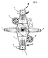
- the gripper according to Figures 1 to 3 has a gripper crossbar 1, which struck a load hook 2 of a crane is.
- Two load arms protrude from the gripper crossbar 1 3 down, which are arranged diametrically to each other.
- Each support arm 3 has a gripping element at its lower end in the form of a jack 4.
- the pawls 4 In the position according to the figure 1 engage the pawls 4 one formed by a recess circumferential shoulder 5 of a container 6, in the present Case of a shielding container.
- the distance between the two support arms 3 is on the diameter of the container 6 adjusted.
- Centering elements 7 ensure a central alignment.
- centering arms also protrude from the gripper crossbar 1 8 down. These are also diametrical to each other arranged and offset by 90 ° against the support arms 3.
- the Centering arms 8 are provided with centering elements 9 which correspond to the centering elements 7 of the support arms 3.
- the Gripper moved centrally over the container and then lowered.
- the pawls 4 take their open position according to Figure 3.
- the gripper is lowered so far, that the pawls 4 the circumferential shoulder 5 of the container can reach under, the pawls 4 from their open position according to Figure 3 in its closed position Figure 1 pivoted.
- This is represented by a vertical one Shaft 10 causes which passes through the associated bracket 3 and with the interposition of a universal joint 11 connected to a worm gear motor 12 is.
- the worm gear motors 12 are on the Gripper crossbar 1 arranged.
- the jack 4 are in the associated Support arms 3 mounted so that by the load of Container 6 no forces on the vertical shafts 10th be exercised.
- each pawl has two limit switches 13 for this purpose (only one is visible in Figure 4) assigned to the a cam 14 run. The latter is associated with the vertical shaft 10 driven. A lifting and Lowering the gripper is only possible if the pawls 4 assume one of their end positions.
- FIG. 5 shows that each centering arm 8 in a sensor Form of an ultrasonic proximity switch 15 is assigned.
- the proximity switches 15 are, as can be clearly seen from FIG. 2, directed against the container 6.
- the proximity switches lock when the gripper is lowered 15 an actuation of the worm gear motor 12. Only when the one forming the circumferential shoulder 5 Return at the bottom of the container 6 is reached, this will Blocking removed. This ensures that the pawls 4 have come into a position in which they are rotating Can reach under shoulder 5.
- the gripper via a mechanical lock.
- the drive power and gear ratio are dimensioned so that the latches cannot be opened under load is.
- the gripper crossbar 1 provided with two upwardly directed pins 16. These are arranged diametrically to each other and serve to engage in corresponding recordings of the trolley of the Crane. This will make the load oscillate in the raised position prevented. The insertion of the pin 16 in the recordings takes place automatically because the load hook is opposite its Suspension is non-rotatable.
- the control of the gripper can be controlled by the Be coupled crane. Monitoring is by visual contact possible or also via cameras and associated monitors.
- the gripper may be activated drove together with container 6 in a repair station, in which the grippers may need to be operated manually Helical-worm geared motors are opened. Act it a shielding container with a high dose rate, so is carried out manually using remote-controlled Manipulators.
- the gripper according to the invention due to its conception is especially suitable for shielding containers with high Manage dose rate.
- the proportion of electronic Components are small, and these can easily be adjusted Can be provided with simple shields if required.
- the gripper is simple in construction and reliable operational. It allows containers to be which are arranged close together in a vertical orientation are.
- the circulating Shoulder which forms the engagement surface for the pawls, also be the top surface of a groove. However, then the axial extension of the groove is sufficient, the ultrasonic proximity switches to take effect.
- the shoulder will be trained as it is in the Figures 1 and 2 is shown.
- the engagement surfaces can also be formed by pockets.
- Another option consists of only one of the centering arms, and the one with an ultrasonic proximity switch is provided to train in full length and the other Shorten the centering arm so that it only has its centering function Fulfills.
- tragund have the same length
- Centering arms have the advantage that the gripper without tools can be parked on the floor.
- the cones that prevent the pendulum movement of the gripper when the load is raised can be arranged so that they function both when the trolley is moving and when it is moving the crane bridge.
- the length of the peg depends on how far the top height position of the gripper away from the crane's trolley. Schneckenstirnradgetriebemotoren are preferably used, however any other drives are also possible, for example hydraulic or pneumatic drives with interposition of timing belts or other gears.
Landscapes
- Engineering & Computer Science (AREA)
- Mechanical Engineering (AREA)
- Load-Engaging Elements For Cranes (AREA)
- Filling Of Jars Or Cans And Processes For Cleaning And Sealing Jars (AREA)
- Transition And Organic Metals Composition Catalysts For Addition Polymerization (AREA)
- Handcart (AREA)
- Specific Conveyance Elements (AREA)
Abstract
Description
- einer Greifertraverse, die an einer Hubeinrichtung, insbesondere an einem Kran, befestigt oder befestigbar ist,
- zwei Tragarmen, die, einander diametral gegenüberliegend, von der Greifertraverse aus nach unten ragen und an ihren unteren Enden Greifelemente zum Untergreifen der Eingriffsflächen der Behälter aufweisen, wobei der Abstand zwischen den Tragarmen an den Durchmesser der Behälter angepaßt ist, und
- zwei Zentrierarmen, die, jeweils um etwa 90° gegen die Tragarme versetzt, von der Greifertraverse aus nach unten ragen, wobei der Abstand zwischen den Zentrierarmen an den Durchmesser der Behälter angepaßt ist.
Claims (15)
- Greifer zum Transportieren von Behältern (6), die in senkrechter Ausrichtung angeordnet sind und jeweils im wesentlichen horizontale, von unten aus zugängliche Eingriffsflächen (5) bilden, miteiner Greifertraverse (1), die an einer Hubeinrichtung, insbesondere an einem Kran befestigt oder befestigbar ist,zwei Tragarmen (3), die, einander diametral gegenüberliegend, von der Greifertraverse (1) aus nach unten ragen und an ihren unteren Enden Greifelemente (4) zum Untergreifen der Eingriffsflächen (5) der Behälter (6) aufweisen, wobei der Abstand zwischen den Tragarmen (3) an den Durchmesser der Behälter (6) angepaßt ist, undzwei Zentrierarmen (8), die, jeweils um etwa 90° gegen die Tragarme (3) versetzt, von der Greifertraverse (1) aus nach unten ragen, wobei der Abstand zwischen den Zentrierarmen (8) an den Durchmesser der Behälter (6) angepaßt ist.
- Greifer nach Anspruch 1, dadurch gekennzeichnet, daß die Trag- und/oder die Zentrierarme (3 bzw. 8) radial verstellbar an der Greifertraverse (1) angeordnet sind.
- Greifer nach Anspruch 1 oder 2, dadurch gekennzeichnet, daß die Eingriffsflächen der Behälter (6) als umlaufende Schulter (5) ausgebildet sind.
- Greifer nach einem der Ansprüche 1 bis 3, dadurch gekennzeichnet, daß die Greifelemente als Klinken (4) ausgebildet sind, die jeweils um eine vertikale, durch den zugehörigen Tragarm (3) laufende Achse drehbar sind.
- Greifer nach Anspruch 4, dadurch gekennzeichnet, daß die Klinken (4) jeweils im zugehörigen Tragarm (3) gelagert und von einer im Tragarm (3) verlaufenden vertikalen Welle (10) antreibbar sind.
- Greifer nach Anspruch 5, dadurch gekennzeichnet, daß die Wellen (10) jeweils über ein Kreuzgelenk (11) an einen zugehörigen Antrieb (12) angeschlossen sind.
- Greifer nach Anspruch 6, dadurch gekennzeichnet, daß die Antriebe als Schneckenstirnradgetriebemotoren (12) ausgebildet sind.
- Greifer nach Anspruch 6 oder 7, dadurch gekennzeichnet, daß die Antriebe (12) manuell betätigbar sind.
- Greifer nach einem der Ansprüche 4 bis 8, dadurch gekennzeichnet, daß die Endpositionen der Klinken (4) jeweils durch Anschläge definiert sind.
- Greifer nach einem der Ansprüche 4 bis 9, dadurch gekennzeichnet, daß die Endpositionen der Klinken (4) jeweils von Endschaltern (13) überwacht werden, die paarweise auf einer von der zugehörigen Welle (10) angetriebenen Kurvenscheibe (14) laufen.
- Greifer nach einem der Ansprüche 1 bis 10, dadurch gekennzeichnet, daß mindestens einer der Zentrierarme (8) an seinem unteren Ende einen Sensor (15) trägt, der radial einwärts gerichtet ist und eine Eingriffsfläche (5) der Behälter (6) erfaßt.
- Greifer nach Anspruch 11, dadurch gekennzeichnet, daß der Sensor als Ultraschall-Näherungsschalter (15) ausgebildet ist.
- Greifer nach einem der Ansprüche 4 bis 12, dadurch gekennzeichnet, daß die Dimensionierung der Antriebsleistung und der Getriebeübersetzung eine mechanische Verriegelung der Klinken (4) bewirkt.
- Greifer nach einem der Ansprüche 1 bis 13, dadurch gekennzeichnet, daß die Traverse (1) mindestens einen nach oben ragenden Zapfen (16) zum Eingriff in eine komplementäre Aufnahme der Hubeinrichtung trägt.
- Greifer nach Anspruch 14, dadurch gekennzeichnet, daß zwei einander diametral gegenüberliegende Zapfen (16) vorgesehen sind.
Applications Claiming Priority (2)
| Application Number | Priority Date | Filing Date | Title |
|---|---|---|---|
| DE10217012A DE10217012B4 (de) | 2002-04-16 | 2002-04-16 | Greifer |
| DE10217012 | 2002-04-16 |
Publications (3)
| Publication Number | Publication Date |
|---|---|
| EP1354840A2 true EP1354840A2 (de) | 2003-10-22 |
| EP1354840A3 EP1354840A3 (de) | 2005-05-25 |
| EP1354840B1 EP1354840B1 (de) | 2009-07-29 |
Family
ID=28458885
Family Applications (1)
| Application Number | Title | Priority Date | Filing Date |
|---|---|---|---|
| EP03008046A Expired - Lifetime EP1354840B1 (de) | 2002-04-16 | 2003-04-14 | Greifer |
Country Status (4)
| Country | Link |
|---|---|
| EP (1) | EP1354840B1 (de) |
| AT (1) | ATE437838T1 (de) |
| DE (2) | DE10217012B4 (de) |
| ES (1) | ES2329885T3 (de) |
Cited By (3)
| Publication number | Priority date | Publication date | Assignee | Title |
|---|---|---|---|---|
| FR2873670A1 (fr) * | 2004-07-29 | 2006-02-03 | Butagaz Snc | Palonnier de manutention d'une charge |
| DE102009023791A1 (de) * | 2009-06-03 | 2010-12-09 | Huthloff, Nicolas Robert | Hebevorrichtung für Rohre |
| DE202010008450U1 (de) * | 2010-09-03 | 2011-12-06 | Kb Anlagentechnik Gmbh | Handhabungsgerät für Spaltbandringe |
Citations (8)
| Publication number | Priority date | Publication date | Assignee | Title |
|---|---|---|---|---|
| US1767525A (en) * | 1927-01-05 | 1930-06-24 | Milwaukee Electric Crane & Mfg | Lumber grapple |
| GB1146193A (en) * | 1966-09-02 | 1969-03-19 | Morris Ltd Herbert | Lifting frame for engaging loads |
| DE1556342A1 (de) * | 1968-02-09 | 1970-01-29 | Demag Zug Gmbh | Stapelgreifvorrichtung |
| DE2523417A1 (de) * | 1975-05-27 | 1976-12-02 | Erwin Jenkner | Fahrbare, pendelfreie hubeinrichtung mit baendern, welche im rechten winkel zueinander angeordnet sind |
| GB2037251A (en) * | 1978-11-29 | 1980-07-09 | Nukem Gmbh | Universal cask grab |
| DE3042174A1 (de) * | 1980-11-08 | 1982-06-16 | Enzinger-Union-Werke Ag, 6800 Mannheim | Verfahrbarer greifer zum schichtenweisen beladen von mit zwischenpaletten palettierten kreiszylindrischen behaeltern, insbesondere faessern |
| US4336460A (en) * | 1979-07-25 | 1982-06-22 | Nuclear Assurance Corp. | Spent fuel cask |
| DE4217333A1 (de) * | 1992-05-26 | 1993-12-02 | Wimo Hebetechnik Gmbh | Hebezeug für Lasten |
-
2002
- 2002-04-16 DE DE10217012A patent/DE10217012B4/de not_active Expired - Fee Related
-
2003
- 2003-04-14 EP EP03008046A patent/EP1354840B1/de not_active Expired - Lifetime
- 2003-04-14 AT AT03008046T patent/ATE437838T1/de not_active IP Right Cessation
- 2003-04-14 ES ES03008046T patent/ES2329885T3/es not_active Expired - Lifetime
- 2003-04-14 DE DE50311743T patent/DE50311743D1/de not_active Expired - Lifetime
Patent Citations (8)
| Publication number | Priority date | Publication date | Assignee | Title |
|---|---|---|---|---|
| US1767525A (en) * | 1927-01-05 | 1930-06-24 | Milwaukee Electric Crane & Mfg | Lumber grapple |
| GB1146193A (en) * | 1966-09-02 | 1969-03-19 | Morris Ltd Herbert | Lifting frame for engaging loads |
| DE1556342A1 (de) * | 1968-02-09 | 1970-01-29 | Demag Zug Gmbh | Stapelgreifvorrichtung |
| DE2523417A1 (de) * | 1975-05-27 | 1976-12-02 | Erwin Jenkner | Fahrbare, pendelfreie hubeinrichtung mit baendern, welche im rechten winkel zueinander angeordnet sind |
| GB2037251A (en) * | 1978-11-29 | 1980-07-09 | Nukem Gmbh | Universal cask grab |
| US4336460A (en) * | 1979-07-25 | 1982-06-22 | Nuclear Assurance Corp. | Spent fuel cask |
| DE3042174A1 (de) * | 1980-11-08 | 1982-06-16 | Enzinger-Union-Werke Ag, 6800 Mannheim | Verfahrbarer greifer zum schichtenweisen beladen von mit zwischenpaletten palettierten kreiszylindrischen behaeltern, insbesondere faessern |
| DE4217333A1 (de) * | 1992-05-26 | 1993-12-02 | Wimo Hebetechnik Gmbh | Hebezeug für Lasten |
Cited By (3)
| Publication number | Priority date | Publication date | Assignee | Title |
|---|---|---|---|---|
| FR2873670A1 (fr) * | 2004-07-29 | 2006-02-03 | Butagaz Snc | Palonnier de manutention d'une charge |
| DE102009023791A1 (de) * | 2009-06-03 | 2010-12-09 | Huthloff, Nicolas Robert | Hebevorrichtung für Rohre |
| DE202010008450U1 (de) * | 2010-09-03 | 2011-12-06 | Kb Anlagentechnik Gmbh | Handhabungsgerät für Spaltbandringe |
Also Published As
| Publication number | Publication date |
|---|---|
| EP1354840B1 (de) | 2009-07-29 |
| DE10217012A1 (de) | 2003-11-13 |
| ES2329885T3 (es) | 2009-12-02 |
| ATE437838T1 (de) | 2009-08-15 |
| DE10217012B4 (de) | 2006-07-13 |
| DE50311743D1 (de) | 2009-09-10 |
| EP1354840A3 (de) | 2005-05-25 |
Similar Documents
| Publication | Publication Date | Title |
|---|---|---|
| DE102011117487B3 (de) | Lagersystem mit mehreren Gassen und automatisiertes Verfahren zum Betreiben desselben, während eine Gasse im Wartungsmodus ist | |
| EP2185382B1 (de) | Vorrichtung zum sichern eines containers auf einer plattform eines transportfahrzeugs | |
| WO2000014772A1 (de) | Vorrichtung und verfahren zum handhaben von einzelnen wafern | |
| DE102009051583A1 (de) | Robotersystem und Verfahren zum Verlegen eines Schienenstrangs | |
| WO2016124460A1 (de) | Längsförderer zum ein- und auslagern von ladehilfsmitteln | |
| EP0863098A2 (de) | Vorrichtung zum Handhaben von Bobinen | |
| DE3621648C2 (de) | Ladegeschirr, insbesondere Spreader, und Verfahren zum Ankuppeln von Containern an dasselbe | |
| DE3839550A1 (de) | Anlage zum auskleiden der innenwand einer umhuellung mit ziegelsteinen | |
| EP1354840B1 (de) | Greifer | |
| DE10147360A1 (de) | Verpackungsmaschine mit schmalem Säulenverbinder | |
| EP0267178B1 (de) | Vorrichtung zum Lagern von Werkstücken annähernd gleicher Form und Grösse im Abstand übereinander | |
| DE60005748T2 (de) | Handhabungsroboter und vorrichtung mit einem solchen roboter | |
| DE102017114643A1 (de) | Regalbediengerät geeignet für den Einsatz in einem Hochregallager | |
| DE202005020225U1 (de) | Transporteinrichtung | |
| EP0983899A2 (de) | Ladevorrichtung zum Be- und Entladen eines Fahrzeuges | |
| DE60208874T2 (de) | Verfahren und Anordnung zum Be- und Entladen von Rollcontainern | |
| EP0639527A1 (de) | Ladegeschirr mit beweglichen Kupplungsorganen, insbesondere verdrehbaren Verriegelungsbolzen | |
| WO2001083355A1 (de) | Auslegegerät zum verriegeln und entriegeln von behältern, insbesondere von mehreren übereinander abgeordeneten behältern, und verfahren hierzu | |
| DE102017112878A1 (de) | Ladungsträgerwechselsystem | |
| EP2672058A2 (de) | Verfahren und Vorrichtung zum Verschließen der Enden von Bohrgestängeelementen | |
| DE102013010455B4 (de) | Verfahren zum Herstellen einer Sicherheitsplattform | |
| DE19812969A1 (de) | Teleskopgeführter Kran | |
| CH696687A5 (de) | Regallager mit verschiebbaren Toren. | |
| EP1409373A1 (de) | Verriegelungsmechanismus für behälter, insbesondere container | |
| DE2054868A1 (de) | Selbstausrichtende Vernegelungs einrichtung an einem Container Verlade rahmen |
Legal Events
| Date | Code | Title | Description |
|---|---|---|---|
| PUAI | Public reference made under article 153(3) epc to a published international application that has entered the european phase |
Free format text: ORIGINAL CODE: 0009012 |
|
| AK | Designated contracting states |
Kind code of ref document: A2 Designated state(s): AT BE BG CH CY CZ DE DK EE ES FI FR GB GR HU IE IT LI LU MC NL PT RO SE SI SK TR |
|
| AX | Request for extension of the european patent |
Extension state: AL LT LV MK |
|
| PUAL | Search report despatched |
Free format text: ORIGINAL CODE: 0009013 |
|
| AK | Designated contracting states |
Kind code of ref document: A3 Designated state(s): AT BE BG CH CY CZ DE DK EE ES FI FR GB GR HU IE IT LI LU MC NL PT RO SE SI SK TR |
|
| AX | Request for extension of the european patent |
Extension state: AL LT LV MK |
|
| AKX | Designation fees paid |
Designated state(s): AT BE BG CH CY CZ DE DK EE ES FI FR GB GR HU IE IT LI LU MC NL PT RO SE SI SK TR |
|
| 17P | Request for examination filed |
Effective date: 20060102 |
|
| R17P | Request for examination filed (corrected) |
Effective date: 20051107 |
|
| 17Q | First examination report despatched |
Effective date: 20060102 |
|
| RAP1 | Party data changed (applicant data changed or rights of an application transferred) |
Owner name: STEAG ENCOTEC GMBH |
|
| RAP1 | Party data changed (applicant data changed or rights of an application transferred) |
Owner name: EVONIK ENERGY SERVICES GMBH |
|
| GRAP | Despatch of communication of intention to grant a patent |
Free format text: ORIGINAL CODE: EPIDOSNIGR1 |
|
| GRAS | Grant fee paid |
Free format text: ORIGINAL CODE: EPIDOSNIGR3 |
|
| GRAA | (expected) grant |
Free format text: ORIGINAL CODE: 0009210 |
|
| AK | Designated contracting states |
Kind code of ref document: B1 Designated state(s): AT BE BG CH CY CZ DE DK EE ES FI FR GB GR HU IE IT LI LU MC NL PT RO SE SI SK TR |
|
| REG | Reference to a national code |
Ref country code: GB Ref legal event code: FG4D Free format text: NOT ENGLISH |
|
| REG | Reference to a national code |
Ref country code: CH Ref legal event code: EP |
|
| REG | Reference to a national code |
Ref country code: IE Ref legal event code: FG4D |
|
| REF | Corresponds to: |
Ref document number: 50311743 Country of ref document: DE Date of ref document: 20090910 Kind code of ref document: P |
|
| REG | Reference to a national code |
Ref country code: CH Ref legal event code: NV Representative=s name: KELLER & PARTNER PATENTANWAELTE AG |
|
| REG | Reference to a national code |
Ref country code: ES Ref legal event code: FG2A Ref document number: 2329885 Country of ref document: ES Kind code of ref document: T3 |
|
| NLV1 | Nl: lapsed or annulled due to failure to fulfill the requirements of art. 29p and 29m of the patents act | ||
| PG25 | Lapsed in a contracting state [announced via postgrant information from national office to epo] |
Ref country code: SE Free format text: LAPSE BECAUSE OF FAILURE TO SUBMIT A TRANSLATION OF THE DESCRIPTION OR TO PAY THE FEE WITHIN THE PRESCRIBED TIME-LIMIT Effective date: 20090729 |
|
| PG25 | Lapsed in a contracting state [announced via postgrant information from national office to epo] |
Ref country code: NL Free format text: LAPSE BECAUSE OF FAILURE TO SUBMIT A TRANSLATION OF THE DESCRIPTION OR TO PAY THE FEE WITHIN THE PRESCRIBED TIME-LIMIT Effective date: 20090729 Ref country code: SI Free format text: LAPSE BECAUSE OF FAILURE TO SUBMIT A TRANSLATION OF THE DESCRIPTION OR TO PAY THE FEE WITHIN THE PRESCRIBED TIME-LIMIT Effective date: 20090729 |
|
| REG | Reference to a national code |
Ref country code: IE Ref legal event code: FD4D |
|
| PG25 | Lapsed in a contracting state [announced via postgrant information from national office to epo] |
Ref country code: PT Free format text: LAPSE BECAUSE OF FAILURE TO SUBMIT A TRANSLATION OF THE DESCRIPTION OR TO PAY THE FEE WITHIN THE PRESCRIBED TIME-LIMIT Effective date: 20091129 Ref country code: BG Free format text: LAPSE BECAUSE OF FAILURE TO SUBMIT A TRANSLATION OF THE DESCRIPTION OR TO PAY THE FEE WITHIN THE PRESCRIBED TIME-LIMIT Effective date: 20091029 |
|
| PG25 | Lapsed in a contracting state [announced via postgrant information from national office to epo] |
Ref country code: IE Free format text: LAPSE BECAUSE OF FAILURE TO SUBMIT A TRANSLATION OF THE DESCRIPTION OR TO PAY THE FEE WITHIN THE PRESCRIBED TIME-LIMIT Effective date: 20090729 Ref country code: RO Free format text: LAPSE BECAUSE OF FAILURE TO SUBMIT A TRANSLATION OF THE DESCRIPTION OR TO PAY THE FEE WITHIN THE PRESCRIBED TIME-LIMIT Effective date: 20090729 Ref country code: EE Free format text: LAPSE BECAUSE OF FAILURE TO SUBMIT A TRANSLATION OF THE DESCRIPTION OR TO PAY THE FEE WITHIN THE PRESCRIBED TIME-LIMIT Effective date: 20090729 Ref country code: CZ Free format text: LAPSE BECAUSE OF FAILURE TO SUBMIT A TRANSLATION OF THE DESCRIPTION OR TO PAY THE FEE WITHIN THE PRESCRIBED TIME-LIMIT Effective date: 20090729 Ref country code: DK Free format text: LAPSE BECAUSE OF FAILURE TO SUBMIT A TRANSLATION OF THE DESCRIPTION OR TO PAY THE FEE WITHIN THE PRESCRIBED TIME-LIMIT Effective date: 20090729 |
|
| PG25 | Lapsed in a contracting state [announced via postgrant information from national office to epo] |
Ref country code: SK Free format text: LAPSE BECAUSE OF FAILURE TO SUBMIT A TRANSLATION OF THE DESCRIPTION OR TO PAY THE FEE WITHIN THE PRESCRIBED TIME-LIMIT Effective date: 20090729 |
|
| PLBE | No opposition filed within time limit |
Free format text: ORIGINAL CODE: 0009261 |
|
| STAA | Information on the status of an ep patent application or granted ep patent |
Free format text: STATUS: NO OPPOSITION FILED WITHIN TIME LIMIT |
|
| 26N | No opposition filed |
Effective date: 20100503 |
|
| PG25 | Lapsed in a contracting state [announced via postgrant information from national office to epo] |
Ref country code: GR Free format text: LAPSE BECAUSE OF FAILURE TO SUBMIT A TRANSLATION OF THE DESCRIPTION OR TO PAY THE FEE WITHIN THE PRESCRIBED TIME-LIMIT Effective date: 20091030 |
|
| BERE | Be: lapsed |
Owner name: EVONIK ENERGY SERVICES G.M.B.H. Effective date: 20100430 |
|
| PG25 | Lapsed in a contracting state [announced via postgrant information from national office to epo] |
Ref country code: MC Free format text: LAPSE BECAUSE OF NON-PAYMENT OF DUE FEES Effective date: 20100430 |
|
| PG25 | Lapsed in a contracting state [announced via postgrant information from national office to epo] |
Ref country code: BE Free format text: LAPSE BECAUSE OF NON-PAYMENT OF DUE FEES Effective date: 20100430 Ref country code: IT Free format text: LAPSE BECAUSE OF FAILURE TO SUBMIT A TRANSLATION OF THE DESCRIPTION OR TO PAY THE FEE WITHIN THE PRESCRIBED TIME-LIMIT Effective date: 20090729 |
|
| PG25 | Lapsed in a contracting state [announced via postgrant information from national office to epo] |
Ref country code: AT Free format text: LAPSE BECAUSE OF NON-PAYMENT OF DUE FEES Effective date: 20100414 |
|
| REG | Reference to a national code |
Ref country code: CH Ref legal event code: PFA Owner name: STEAG ENERGY SERVICES GMBH Free format text: EVONIK ENERGY SERVICES GMBH#RELLINGHAUSER STRASSE 1-11#45128 ESSEN (DE) -TRANSFER TO- STEAG ENERGY SERVICES GMBH#RUETTENSCHEIDER STRASSE 1-3#45128 ESSEN (DE) |
|
| REG | Reference to a national code |
Ref country code: FR Ref legal event code: CA Effective date: 20111108 Ref country code: FR Ref legal event code: CD Owner name: STEAG ENERGY SERVICES GMBH, DE Effective date: 20111108 |
|
| REG | Reference to a national code |
Ref country code: DE Ref legal event code: R081 Ref document number: 50311743 Country of ref document: DE Owner name: STEAG ENERGY SERVICES GMBH, DE Free format text: FORMER OWNER: EVONIK ENERGY SERVICES GMBH, 45128 ESSEN, DE Effective date: 20120110 |
|
| REG | Reference to a national code |
Ref country code: ES Ref legal event code: PC2A Owner name: STEAG ENERGY SERVICES GMBH Effective date: 20120314 |
|
| PG25 | Lapsed in a contracting state [announced via postgrant information from national office to epo] |
Ref country code: CY Free format text: LAPSE BECAUSE OF FAILURE TO SUBMIT A TRANSLATION OF THE DESCRIPTION OR TO PAY THE FEE WITHIN THE PRESCRIBED TIME-LIMIT Effective date: 20090729 |
|
| PG25 | Lapsed in a contracting state [announced via postgrant information from national office to epo] |
Ref country code: LU Free format text: LAPSE BECAUSE OF NON-PAYMENT OF DUE FEES Effective date: 20100414 Ref country code: HU Free format text: LAPSE BECAUSE OF FAILURE TO SUBMIT A TRANSLATION OF THE DESCRIPTION OR TO PAY THE FEE WITHIN THE PRESCRIBED TIME-LIMIT Effective date: 20100130 |
|
| PG25 | Lapsed in a contracting state [announced via postgrant information from national office to epo] |
Ref country code: TR Free format text: LAPSE BECAUSE OF FAILURE TO SUBMIT A TRANSLATION OF THE DESCRIPTION OR TO PAY THE FEE WITHIN THE PRESCRIBED TIME-LIMIT Effective date: 20090729 |
|
| PGFP | Annual fee paid to national office [announced via postgrant information from national office to epo] |
Ref country code: GB Payment date: 20140422 Year of fee payment: 12 |
|
| PGFP | Annual fee paid to national office [announced via postgrant information from national office to epo] |
Ref country code: FR Payment date: 20140422 Year of fee payment: 12 Ref country code: FI Payment date: 20140411 Year of fee payment: 12 Ref country code: ES Payment date: 20140424 Year of fee payment: 12 Ref country code: CH Payment date: 20140418 Year of fee payment: 12 Ref country code: DE Payment date: 20140430 Year of fee payment: 12 |
|
| REG | Reference to a national code |
Ref country code: CH Ref legal event code: PCAR Free format text: NEW ADDRESS: EIGERSTRASSE 2 POSTFACH, 3000 BERN 14 (CH) |
|
| REG | Reference to a national code |
Ref country code: DE Ref legal event code: R119 Ref document number: 50311743 Country of ref document: DE |
|
| REG | Reference to a national code |
Ref country code: CH Ref legal event code: PL |
|
| GBPC | Gb: european patent ceased through non-payment of renewal fee |
Effective date: 20150414 |
|
| PG25 | Lapsed in a contracting state [announced via postgrant information from national office to epo] |
Ref country code: FI Free format text: LAPSE BECAUSE OF NON-PAYMENT OF DUE FEES Effective date: 20150414 Ref country code: CH Free format text: LAPSE BECAUSE OF NON-PAYMENT OF DUE FEES Effective date: 20150430 Ref country code: DE Free format text: LAPSE BECAUSE OF NON-PAYMENT OF DUE FEES Effective date: 20151103 Ref country code: LI Free format text: LAPSE BECAUSE OF NON-PAYMENT OF DUE FEES Effective date: 20150430 Ref country code: GB Free format text: LAPSE BECAUSE OF NON-PAYMENT OF DUE FEES Effective date: 20150414 |
|
| REG | Reference to a national code |
Ref country code: FR Ref legal event code: ST Effective date: 20151231 |
|
| PG25 | Lapsed in a contracting state [announced via postgrant information from national office to epo] |
Ref country code: FR Free format text: LAPSE BECAUSE OF NON-PAYMENT OF DUE FEES Effective date: 20150430 |
|
| REG | Reference to a national code |
Ref country code: ES Ref legal event code: FD2A Effective date: 20160531 |
|
| PG25 | Lapsed in a contracting state [announced via postgrant information from national office to epo] |
Ref country code: ES Free format text: LAPSE BECAUSE OF NON-PAYMENT OF DUE FEES Effective date: 20150415 |