EP1354840A2 - Gripper - Google Patents
Gripper Download PDFInfo
- Publication number
- EP1354840A2 EP1354840A2 EP03008046A EP03008046A EP1354840A2 EP 1354840 A2 EP1354840 A2 EP 1354840A2 EP 03008046 A EP03008046 A EP 03008046A EP 03008046 A EP03008046 A EP 03008046A EP 1354840 A2 EP1354840 A2 EP 1354840A2
- Authority
- EP
- European Patent Office
- Prior art keywords
- gripper
- gripper according
- containers
- pawls
- arms
- Prior art date
- Legal status (The legal status is an assumption and is not a legal conclusion. Google has not performed a legal analysis and makes no representation as to the accuracy of the status listed.)
- Granted
Links
Images


Classifications
-
- B—PERFORMING OPERATIONS; TRANSPORTING
- B66—HOISTING; LIFTING; HAULING
- B66C—CRANES; LOAD-ENGAGING ELEMENTS OR DEVICES FOR CRANES, CAPSTANS, WINCHES, OR TACKLES
- B66C1/00—Load-engaging elements or devices attached to lifting or lowering gear of cranes or adapted for connection therewith for transmitting lifting forces to articles or groups of articles
- B66C1/10—Load-engaging elements or devices attached to lifting or lowering gear of cranes or adapted for connection therewith for transmitting lifting forces to articles or groups of articles by mechanical means
- B66C1/22—Rigid members, e.g. L-shaped members, with parts engaging the under surface of the loads; Crane hooks
- B66C1/28—Duplicate, e.g. pivoted, members engaging the loads from two sides
Definitions
- the invention relates to a gripper for transportation of containers arranged in a vertical orientation are and essentially horizontal, from below form accessible engagement surfaces.
- the containers mentioned here are above all about shielding containers for holding radioactive material. Show individual groups of containers different from each other, but uniform within the groups Dimensions on.
- the invention has for its object a gripper of the type mentioned at the beginning, which is able to pick up the containers even if they are close together stand.
- This gripper can be referred to as a two-armed gripper because it only has two support arms.
- the two Centering arms ensure that the gripper is central lowered onto the respective container.
- the gripper is able to pick up the containers even if when they're close together. Become frequent the containers delivered as "six pack". Thereby form the six containers in the plan a rectangle that from close surrounding walls. Nevertheless, the gripper can to take every single container from the "six pack” and raise.
- the containers are common also delivered in a different formation, as a rule, however close together, so tightly packed. same for for the storage of the containers.
- the main advantage of Invention is to accommodate such tightly packed containers transport and in dense formation again to be able to sell. Of course you can too free-standing containers can be handled.
- the gripper according to the invention is applicable to containers different cross-sectional shapes, also on polygonal containers, for example square, octagonal or hexagonal containers, or on oval containers.
- the main field of application of the invention is round Containers such as those mentioned above Shielding containers are represented.
- the four arms of the gripper which are preferably exactly in the are at right angles to each other, find enough space between the container to be accommodated and the neighboring ones Containers or walls.
- a three-armed gripper like him is known in practice, is not able to do this.
- the two diametrically opposite support arms have sufficient carrying capacity to accommodate everyone to transport the container in question.
- An axial There is no load on the centering arms.
- the main function the centering arm consists of the support arms in one To attack position on the containers in which the Container weight is evenly distributed on the support arms.
- the centering arms take over when the load oscillates also radial support functions. A sliding out of the Containers from the support arms are reliably prevented.
- the length of the support and centering arms can be chosen that containers of different heights are transported can be.
- the gripper is then actually adjusted only required in the radial direction, depending on the situation of different container diameters.
- the support and / or the centering arms are radially adjustable to be arranged on the gripper crossbar. The gripper is then able to make containers with different diameters to handle.
- the engagement surfaces by the gripping elements of the Support arms can be gripped differently his.
- the upper boundaries form the engagement surfaces and into the the gripping elements can intervene.
- the location of the recesses Any height can be chosen.
- the Formation of recesses requires that the gripper in defined angular position is lowered onto the container. Accordingly, the engagement surfaces may be more advantageous to form the container as all-round shoulders.
- the angular position of the gripper plays in these circumstances not matter.
- the circumferential shoulder can be from the top Boundary surface of a groove can be formed on any Height is arranged in the container wall. In all As a rule, one will proceed in such a way that the circumferential shoulder of a recess is formed at the bottom of the container.
- the gripping elements are preferably designed as pawls, each one vertical, by the associated one Support arm running axis are rotatable.
- the essential The advantage of this construction is that the waves, which cause the movement of the pawls, of which by the Forces generated by the container load are kept free. You need to just be able to keep the pawls in an unloaded state Swivel condition.
- the forces generated by the load are directly from the pawls into the corresponding support arms initiated.
- the drives preferably as helical geared motors are trained. If the support arms are radially adjustable the construction will be chosen so that the drives can be adjusted together with the support arms.
- the end positions of the pawls are preferably each defined by stops.
- the stops become adjustable train and preferably in the area of the gripper crossbar arrange, i.e. directly below the drives, which is preferred sit on top of the traverse.
- At least one of the centering arms at its lower end carries a sensor that is radial is directed inward and an engagement surface of the Containers detected.
- the gripper lowers onto one of the containers the sensor locks the pawls in their sideways or outward release position, until it is below the level of the engagement surface.
- the arrangement is such that in this position too the pawls at a level below the associated engagement surface lie.
- the sensor now signals an enable for the jack drives. These turn the jacks in their closed position, defined by the associated Stops and monitored by the associated limit switches. As soon as the latter signal the locking process as finished, the gripper can be raised, the Attack pawls on the engagement surfaces of the container and take the latter with you.
- the sensor of the centering arm runs automatically into an area of the container wall that is above the engaging surface.
- the sensor therefore deactivates the Pawl drives so that the pawls open under load is excluded. Only when the container is lowered again has been and the sensor is in the area below the The pawl drives can move again to take action. If one of the drives fails, the container will be transported to a repair station and operate the defective drive by hand and then repair.
- the engagement surfaces for the pawls of the support arms are formed by separate recesses or pockets, also becomes the engagement surface for the sensor of the centering arm formed as the top surface of a pocket.
- the construction is particularly simple, if all surfaces of engagement from a common Shoulder are formed.
- the sensor is then on the same level as the jacks.
- the shoulder forms the upper surface of a groove or pocket, its height must be sufficient, to allow the pawls to be actuated if the sensor falls sufficiently below the level of the shoulder has to be activated.
- the arrangement of a sensor is generally sufficient one of the two support arms. For security reasons it is prefer each of the support arms with a separate sensor equip. Only the enable signals of both sensors are enabled then actuation of the pawl drives.
- the sensors are preferably designed as ultrasonic proximity switches.
- An electronic is carried out via the sensor or sensors Locking of the pawls of the support arms under load.
- mechanical locking is preferred provided by appropriate dimensioning the drive power and the gear ratio. The The frictional resistance of the pawls under load is so great that the drive power is not sufficient for actuation.
- the gripper is particularly suitable for attachment to a crane. He can use the load hook of the crane can be attached or via rollers directly connected to the crane trolley.
- the suspension is usually not rotatable, but allows pendulum movements to the load. Is the gripper up to the top height position and is raised relative to the trolley of the crane the trolley or the crane moves are such pendulum movements the load undesirable.
- the traverse at least an upstanding pin for engaging in a Complementary inclusion of the lifting device carries.
- an upstanding pin is sufficient.
- two diametrically opposite one another are more advantageous Cones.
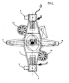
- the gripper according to Figures 1 to 3 has a gripper crossbar 1, which struck a load hook 2 of a crane is.
- Two load arms protrude from the gripper crossbar 1 3 down, which are arranged diametrically to each other.
- Each support arm 3 has a gripping element at its lower end in the form of a jack 4.
- the pawls 4 In the position according to the figure 1 engage the pawls 4 one formed by a recess circumferential shoulder 5 of a container 6, in the present Case of a shielding container.
- the distance between the two support arms 3 is on the diameter of the container 6 adjusted.
- Centering elements 7 ensure a central alignment.
- centering arms also protrude from the gripper crossbar 1 8 down. These are also diametrical to each other arranged and offset by 90 ° against the support arms 3.
- the Centering arms 8 are provided with centering elements 9 which correspond to the centering elements 7 of the support arms 3.
- the Gripper moved centrally over the container and then lowered.
- the pawls 4 take their open position according to Figure 3.
- the gripper is lowered so far, that the pawls 4 the circumferential shoulder 5 of the container can reach under, the pawls 4 from their open position according to Figure 3 in its closed position Figure 1 pivoted.
- This is represented by a vertical one Shaft 10 causes which passes through the associated bracket 3 and with the interposition of a universal joint 11 connected to a worm gear motor 12 is.
- the worm gear motors 12 are on the Gripper crossbar 1 arranged.
- the jack 4 are in the associated Support arms 3 mounted so that by the load of Container 6 no forces on the vertical shafts 10th be exercised.
- each pawl has two limit switches 13 for this purpose (only one is visible in Figure 4) assigned to the a cam 14 run. The latter is associated with the vertical shaft 10 driven. A lifting and Lowering the gripper is only possible if the pawls 4 assume one of their end positions.
- FIG. 5 shows that each centering arm 8 in a sensor Form of an ultrasonic proximity switch 15 is assigned.
- the proximity switches 15 are, as can be clearly seen from FIG. 2, directed against the container 6.
- the proximity switches lock when the gripper is lowered 15 an actuation of the worm gear motor 12. Only when the one forming the circumferential shoulder 5 Return at the bottom of the container 6 is reached, this will Blocking removed. This ensures that the pawls 4 have come into a position in which they are rotating Can reach under shoulder 5.
- the gripper via a mechanical lock.
- the drive power and gear ratio are dimensioned so that the latches cannot be opened under load is.
- the gripper crossbar 1 provided with two upwardly directed pins 16. These are arranged diametrically to each other and serve to engage in corresponding recordings of the trolley of the Crane. This will make the load oscillate in the raised position prevented. The insertion of the pin 16 in the recordings takes place automatically because the load hook is opposite its Suspension is non-rotatable.
- the control of the gripper can be controlled by the Be coupled crane. Monitoring is by visual contact possible or also via cameras and associated monitors.
- the gripper may be activated drove together with container 6 in a repair station, in which the grippers may need to be operated manually Helical-worm geared motors are opened. Act it a shielding container with a high dose rate, so is carried out manually using remote-controlled Manipulators.
- the gripper according to the invention due to its conception is especially suitable for shielding containers with high Manage dose rate.
- the proportion of electronic Components are small, and these can easily be adjusted Can be provided with simple shields if required.
- the gripper is simple in construction and reliable operational. It allows containers to be which are arranged close together in a vertical orientation are.
- the circulating Shoulder which forms the engagement surface for the pawls, also be the top surface of a groove. However, then the axial extension of the groove is sufficient, the ultrasonic proximity switches to take effect.
- the shoulder will be trained as it is in the Figures 1 and 2 is shown.
- the engagement surfaces can also be formed by pockets.
- Another option consists of only one of the centering arms, and the one with an ultrasonic proximity switch is provided to train in full length and the other Shorten the centering arm so that it only has its centering function Fulfills.
- tragund have the same length
- Centering arms have the advantage that the gripper without tools can be parked on the floor.
- the cones that prevent the pendulum movement of the gripper when the load is raised can be arranged so that they function both when the trolley is moving and when it is moving the crane bridge.
- the length of the peg depends on how far the top height position of the gripper away from the crane's trolley. Schneckenstirnradgetriebemotoren are preferably used, however any other drives are also possible, for example hydraulic or pneumatic drives with interposition of timing belts or other gears.
Abstract
Description
Die Erfindung betrifft einen Greifer zum Transportieren von Behältern, die in senkrechter Ausrichtung angeordnet sind und jeweils im wesentlichen horizontale, von unten aus zugängliche Eingriffsflächen bilden.The invention relates to a gripper for transportation of containers arranged in a vertical orientation are and essentially horizontal, from below form accessible engagement surfaces.
Bei den hier angesprochenen Behältern handelt es sich vor allen Dingen um Abschirmbehälter zum Aufnehmen von radioaktivem Material. Einzelne Gruppen der Behälter weisen voneinander verschiedene, innerhalb der Gruppen jedoch einheitliche Abmaße auf.The containers mentioned here are above all about shielding containers for holding radioactive material. Show individual groups of containers different from each other, but uniform within the groups Dimensions on.
Der Erfindung liegt die Aufgabe zugrunde, einen Greifer der eingangs genannten Art zu schaffen, der in der Lage ist, die Behälter auch dann aufzunehmen, wenn diese dicht nebeneinander stehen.The invention has for its object a gripper of the type mentioned at the beginning, which is able to pick up the containers even if they are close together stand.
Zur Lösung dieser Aufgabe ist der Greifer der eingangs genannten Art erfindungsgemäß versehen mit
- einer Greifertraverse, die an einer Hubeinrichtung, insbesondere an einem Kran, befestigt oder befestigbar ist,
- zwei Tragarmen, die, einander diametral gegenüberliegend, von der Greifertraverse aus nach unten ragen und an ihren unteren Enden Greifelemente zum Untergreifen der Eingriffsflächen der Behälter aufweisen, wobei der Abstand zwischen den Tragarmen an den Durchmesser der Behälter angepaßt ist, und
- zwei Zentrierarmen, die, jeweils um etwa 90° gegen die Tragarme versetzt, von der Greifertraverse aus nach unten ragen, wobei der Abstand zwischen den Zentrierarmen an den Durchmesser der Behälter angepaßt ist.
- a gripper traverse which is attached or can be attached to a lifting device, in particular to a crane,
- two support arms which, diametrically opposite one another, project downwards from the gripper crossmember and have gripping elements at their lower ends for engaging under the engagement surfaces of the containers, the distance between the support arms being adapted to the diameter of the containers, and
- two centering arms, each offset by approximately 90 ° against the support arms, projecting downward from the gripper crossmember, the distance between the centering arms being adapted to the diameter of the containers.
Dieser Greifer kann als zweiarmiger Greifer bezeichnet werden, da er lediglich über zwei Tragarme verfügt. Die beiden Zentrierarme sorgen dafür, daß sich der Greifer zentral auf den jeweiligen Behälter absenkt. This gripper can be referred to as a two-armed gripper because it only has two support arms. The two Centering arms ensure that the gripper is central lowered onto the respective container.
Der Greifer ist in der Lage, die Behälter auch dann aufzunehmen, wenn sie dicht nebeneinander stehen. Häufig werden die Behälter als "Sechserpack" angeliefert. Dabei bilden die sechs Behälter im Grundriß ein Rechteck, das von dicht anliegenden Wänden umgeben ist. Dennoch vermag der Greifer jeden einzelnen Behälter aus dem "Sechserpack" zu ergreifen und anzuheben. Selbstverständlich werden die Behälter häufig auch in anderer Formation angeliefert, in aller Regel allerdings dicht nebeneinander, also dicht gepackt. Gleiches gilt für die Lagerung der Behälter. Der wesentliche Vorteil der Erfindung besteht darin, derart dicht gepackte Behälter aufnehmen, transportieren und in dichter Formation wieder absetzen zu können. Selbstverständlich können auch freistehende Behälter gehandhabt werden.The gripper is able to pick up the containers even if when they're close together. Become frequent the containers delivered as "six pack". Thereby form the six containers in the plan a rectangle that from close surrounding walls. Nevertheless, the gripper can to take every single container from the "six pack" and raise. Of course, the containers are common also delivered in a different formation, as a rule, however close together, so tightly packed. same for for the storage of the containers. The main advantage of Invention is to accommodate such tightly packed containers transport and in dense formation again to be able to sell. Of course you can too free-standing containers can be handled.
Der Greifer nach der Erfindung ist anwendbar auf Behälter unterschiedlicher Querschnittsformen, also auch auf polygonale Behälter, beispielsweise viereckige, achteckige oder sechzehneckige Behälter, oder auch auf ovale Behälter. Hauptanwendungsgebiet der Erfindung sind allerdings runde Behälter, wie sie von den eingangs bereits erwähnten Abschirmbehältern repräsentiert werden.The gripper according to the invention is applicable to containers different cross-sectional shapes, also on polygonal containers, for example square, octagonal or hexagonal containers, or on oval containers. The main field of application of the invention, however, is round Containers such as those mentioned above Shielding containers are represented.
Die vier Arme des Greifers, die vorzugsweise exakt im rechten Winkel zueinander stehen, finden ausreichend Platz zwischen dem aufzunehmenden Behälter und den benachbarten Behältern bzw. Wänden. Ein dreiarmiger Greifer, wie er aus der Praxis bekannt ist, ist hierzu nicht in der Lage.The four arms of the gripper, which are preferably exactly in the are at right angles to each other, find enough space between the container to be accommodated and the neighboring ones Containers or walls. A three-armed gripper like him is known in practice, is not able to do this.
Die beiden einander diametral gegenüberliegenden Tragarme besitzen eine ausreichende Tragkapazität, um sämtliche infrage kommenden Behälter zu transportieren. Eine axiale Belastung der Zentrierarme tritt nicht auf. Die Hauptfunktion der Zentrierarme besteht darin, die Tragarme in einer Position an den Behältern angreifen zu lassen, in der das Behältergewicht gleichmäßig auf die Tragarme verteilt ist. Bei Pendelbewegungen der Last übernehmen die Zentrierarme außerdem radiale Stützfunktionen. Ein Herausgleiten der Behälter aus den Tragarmen wird zuverlässig verhindert.The two diametrically opposite support arms have sufficient carrying capacity to accommodate everyone to transport the container in question. An axial There is no load on the centering arms. The main function the centering arm consists of the support arms in one To attack position on the containers in which the Container weight is evenly distributed on the support arms. The centering arms take over when the load oscillates also radial support functions. A sliding out of the Containers from the support arms are reliably prevented.
Die Länge der Trag- und Zentrierarme kann so gewählt werden, daß Behälter unterschiedlicher Höhe transportiert werden können. Eine Anpassung des Greifers ist dann tatsächlich nur in radialer Richtung erforderlich, und zwar abhängig von unterschiedlichen Behälterdurchmessern.The length of the support and centering arms can be chosen that containers of different heights are transported can be. The gripper is then actually adjusted only required in the radial direction, depending on the situation of different container diameters.
Man kann unterschiedliche Greifer für unterschiedliche Behälterdurchmesser konzipieren. Vorteilhafter ist es unter Umständen, die Trag- und/oder die Zentrierarme radial verstellbar an der Greifertraverse anzuordnen. Der Greifer ist dann in der Lage, Behälter mit unterschiedlichen Durchmessern zu handhaben.You can have different grippers for different ones Design the container diameter. It is more advantageous under Circumstances, the support and / or the centering arms are radially adjustable to be arranged on the gripper crossbar. The gripper is then able to make containers with different diameters to handle.
Die Eingriffsflächen, die von den Greifelementen der Tragarme untergriffen werden, können unterschiedlich ausgebildet sein. Zum Beispiel besteht die Möglichkeit, separate Ausnehmungen in den Behälteraußenwänden vorzusehen, deren obere Begrenzungen die Eingriffsflächen bilden und in die die Greifelemente eingreifen können. Die Lage der Ausnehmungen über der Behälterhöhe kann beliebig gewählt werden. Die Ausbildung von Ausnehmungen setzt voraus, daß der Greifer in definierter Winkelposition auf die Behälter abgesenkt wird. Dementsprechend kann es vorteilhafter sein, die Eingriffsflächen der Behälter als umlaufende Schultern auszubilden. Die Winkelposition des Greifers spielt unter diesen Umständen keine Rolle. Die umlaufende Schulter kann von der oberen Begrenzungsfläche einer Nut gebildet werden, die auf beliebiger Höhe in der Behälterwand angeordnet ist. In aller Regel wird man so vorgehen, daß die umlaufende Schulter von einem Rücksprung am Boden des Behälters gebildet wird.The engagement surfaces by the gripping elements of the Support arms can be gripped differently his. For example, there is the option of separate Provide recesses in the container outer walls, the upper boundaries form the engagement surfaces and into the the gripping elements can intervene. The location of the recesses Any height can be chosen. The Formation of recesses requires that the gripper in defined angular position is lowered onto the container. Accordingly, the engagement surfaces may be more advantageous to form the container as all-round shoulders. The angular position of the gripper plays in these circumstances not matter. The circumferential shoulder can be from the top Boundary surface of a groove can be formed on any Height is arranged in the container wall. In all As a rule, one will proceed in such a way that the circumferential shoulder of a recess is formed at the bottom of the container.
Vorzugsweise sind die Greifelemente als Klinken ausgebildet, die jeweils um eine vertikale, durch den zugehörigen Tragarm laufende Achse drehbar sind. Dazu wird in Weiterbildung der Erfindung vorgeschlagen, daß die Klinken jeweils im zugehörigen Tragarm gelagert und von einer im Tragarm verlaufenden vertikalen Welle antreibbar sind. Der wesentliche Vorteil dieser Konstruktion besteht darin, daß die Wellen, die die Bewegung der Klinken bewirken, von den durch die Behälterlast erzeugten Kräften freigehalten werden. Sie müssen lediglich in der Lage sein, die Klinken in unbelastetem Zustand zu verschwenken. Die von der Last erzeugten Kräfte werden von den Klinken direkt in die zugehörigen Tragarme eingeleitet. Grundsätzlich besteht die Möglichkeit, jeden Tragarm mit zwei gegenläufig zueinander drehbaren Klinken auszurüsten und diese über gesonderte Wellen oder auch über eine gemeinsame Welle anzutreiben. Konstruktiv einfacher ist es, jeden Tragarm mit einer einzigen Klinke zu versehen.The gripping elements are preferably designed as pawls, each one vertical, by the associated one Support arm running axis are rotatable. This is in continuing education the invention proposed that the pawls in each associated support arm mounted and from a extending in the support arm vertical shaft can be driven. The essential The advantage of this construction is that the waves, which cause the movement of the pawls, of which by the Forces generated by the container load are kept free. You need to just be able to keep the pawls in an unloaded state Swivel condition. The forces generated by the load are directly from the pawls into the corresponding support arms initiated. Basically, there is the possibility of everyone Support arm with two pawls rotatable in opposite directions equip and this over separate waves or over to drive a common wave. It is constructively easier to provide each arm with a single pawl.
Da die Tragarme gewissen elastischen Verformungen ausgesetzt sind, ist es vorteilhaft, die Wellen jeweils über ein Kreuzgelenk an einen zugehörigen Antrieb anzuschließen.Because the support arms are exposed to certain elastic deformations , it is advantageous to use the waves in each case Connect universal joint to an associated drive.
Grundsätzlich besteht die Möglichkeit, einen gemeinsamen Antrieb zu verwenden. Vorteilhafter hingegen ist es, jeder Welle einen gesonderten Antrieb zuzuordnen, wobei die Antriebe vorzugsweise als Schneckenstirnradgetriebemotoren ausgebildet sind. Sofern die Tragarme radial verstellbar sind, wird man die Konstruktion so wählen, daß die Antriebe zusammen mit den Tragarmen verstellt werden.Basically there is the possibility of a common Drive to use. However, it is more advantageous to everyone Assign a separate drive to the shaft, the drives preferably as helical geared motors are trained. If the support arms are radially adjustable the construction will be chosen so that the drives can be adjusted together with the support arms.
Störungen der Systeme sind naturgemäß nicht auszuschließen. So ist es denkbar, daß sich nach dem Absetzen eines Behälters eine der Klinken nicht mehr über den zugehörigen Antrieb öffnen läßt. Für diesen Fall wird vorgeschlagen, daß die Antriebe manuell betätigbar sind.Naturally, system malfunctions cannot be ruled out. So it is conceivable that after stopping a Container one of the pawls no longer over the associated one Drive opens. In this case it is proposed that the drives can be operated manually.
Die Endpositionen der Klinken sind vorzugsweise jeweils durch Anschläge definiert. Die Anschläge wird man justierbar ausbilden und vorzugsweise im Bereich der Greifertraverse anordnen, also direkt unterhalb der Antriebe, die bevorzugt oben auf der Traverse sitzen.The end positions of the pawls are preferably each defined by stops. The stops become adjustable train and preferably in the area of the gripper crossbar arrange, i.e. directly below the drives, which is preferred sit on top of the traverse.
Eine wesentliche Weiterbildung der Erfindung besteht darin, daß die Endpositionen der Klinken jeweils von Endschaltern überwacht werden, die paarweise auf einer von der zugehörigen Welle angetriebenen Kurvenscheibe laufen. Mit der Kurvenscheibe ist es in besonders einfacher Weise möglich, die Positionsänderungen der Klinken zu erfassen. Schließlich handelt es sich dabei um Änderungen von Winkelpositionen. Je einer der Endschalter signalisiert die Öffnungsstellung und die Schließstellung der zugehörigen Klinke.An essential development of the invention exists in that the end positions of the pawls each of limit switches be monitored in pairs on one of the associated shaft driven cam. With the cam plate, it is possible in a particularly simple manner to record the position changes of the pawls. After all, these are changes in angular positions. One of the limit switches signals the open position and the closed position of the associated Pawl.
Ein wesentlicher Sicherheitsaspekt des gesamten Systems wird dadurch berücksichtigt, daß mindestens einer der Zentrierarme an seinem unteren Ende einen Sensor trägt, der radial einwärts gerichtet ist und eine Eingriffsfläche der Behälter erfaßt. Senkt sich der Greifer auf einen der Behälter ab, so verriegelt der Sensor die Klinken solange in ihrer seitwärts oder auswärts gerichteten Freigabeposition, bis er sich unterhalb der Höhe der Eingriffsfläche befindet. Die Anordnung ist so getroffen, daß in dieser Position auch die Klinken auf einem Niveau unterhalb der zugehörigen Eingriffsfläche liegen. Der Sensor signalisiert nun eine Freigabe für die Klinkenantriebe. Diese drehen die Klinken in deren Schließstellung, definiert durch die zugehörigen Anschläge und überwacht von den zugehörigen Endschaltern. Sobald letztere den Verriegelungsvorgang als beendet signalisieren, kann der Greifer hochgefahren werden, wobei die Klinken an den Eingriffsflächen des Behälters angreifen und letzteren mitnehmen. Dabei läuft der Sensor des Zentrierarms automatisch in einen Bereich der Behälterwand, der oberhalb der Eingriffsfläche liegt. Der Sensor deaktiviert also die Klinkenantriebe, so daß eine Öffnung der Klinken unter Last ausgeschlossen ist. Erst wenn der Behälter wieder abgesenkt worden ist und der Sensor sich in den Bereich unterhalb der Eingriffsfläche bewegt hat, können die Klinkenantriebe wieder in Aktion treten. Sollte einer der Antriebe versagen, wird man den Behälter in eine Reparaturstation transportieren und hier den defekten Antrieb von Hand betätigen und anschließend reparieren. An essential security aspect of the entire system is taken into account in that at least one of the centering arms at its lower end carries a sensor that is radial is directed inward and an engagement surface of the Containers detected. The gripper lowers onto one of the containers the sensor locks the pawls in their sideways or outward release position, until it is below the level of the engagement surface. The arrangement is such that in this position too the pawls at a level below the associated engagement surface lie. The sensor now signals an enable for the jack drives. These turn the jacks in their closed position, defined by the associated Stops and monitored by the associated limit switches. As soon as the latter signal the locking process as finished, the gripper can be raised, the Attack pawls on the engagement surfaces of the container and take the latter with you. The sensor of the centering arm runs automatically into an area of the container wall that is above the engaging surface. The sensor therefore deactivates the Pawl drives so that the pawls open under load is excluded. Only when the container is lowered again has been and the sensor is in the area below the The pawl drives can move again to take action. If one of the drives fails, the container will be transported to a repair station and operate the defective drive by hand and then repair.
Wenn die Eingriffsflächen für die Klinken der Tragarme von gesonderten Ausnehmungen oder Taschen gebildet werden, wird auch die Eingriffsfläche für den Sensor des Zentrierarms als obere Fläche einer Tasche ausgebildet. Hierbei können ohne weiteres Niveauunterschiede zwischen dem Sensor und den Klinken vorgesehen sein. Besonders einfach wird die Konstruktion, wenn sämtliche Eingriffsflächen von einer gemeinsamen Schulter gebildet werden. Der Sensor liegt dann auf demselben Niveau wie die Klinken. Bildet die Schulter die obere Fläche einer Nut oder Tasche, so muß deren Höhe ausreichen, eine Betätigung der Klinken dann zuzulassen, wenn der Sensor das Niveau der Schulter ausreichend unterschritten hat, um aktiviert zu werden.If the engagement surfaces for the pawls of the support arms are formed by separate recesses or pockets, also becomes the engagement surface for the sensor of the centering arm formed as the top surface of a pocket. Here you can without further level differences between the sensor and the pawls may be provided. The construction is particularly simple, if all surfaces of engagement from a common Shoulder are formed. The sensor is then on the same level as the jacks. The shoulder forms the upper surface of a groove or pocket, its height must be sufficient, to allow the pawls to be actuated if the sensor falls sufficiently below the level of the shoulder has to be activated.
Grundsätzlich genügt die Anordnung eines Sensors an einem der beiden Tragarme. Aus Sicherheitsgründen ist es vorzuziehen, jeden der Tragarme mit einem gesonderten Sensor auszurüsten. Erst die Freigabesignale beider Sensoren ermöglicht dann eine Betätigung der Klinkenantriebe. Die Sensoren sind vorzugsweise als Utraschall-Näherungsschalter ausgebildet.The arrangement of a sensor is generally sufficient one of the two support arms. For security reasons it is prefer each of the support arms with a separate sensor equip. Only the enable signals of both sensors are enabled then actuation of the pawl drives. The sensors are preferably designed as ultrasonic proximity switches.
Über den Sensor bzw. die Sensoren erfolgt eine elektronische Verriegelung der Klinken der Tragarme unter Last. Vorzugsweise wird zusätzlich dazu eine mechanische Verriegelung vorgesehen, und zwar durch entsprechende Dimensionierung der Antriebsleistung und der Getriebeübersetzung. Der Reibungswiderstand der Klinken unter Last ist dabei so groß, daß die Antriebsleistung für eine Betätigung nicht ausreicht.An electronic is carried out via the sensor or sensors Locking of the pawls of the support arms under load. In addition, mechanical locking is preferred provided by appropriate dimensioning the drive power and the gear ratio. The The frictional resistance of the pawls under load is so great that the drive power is not sufficient for actuation.
Wie erwähnt, eignet sich der Greifer vor allen Dingen zur Befestigung an einem Kran. Dabei kann er am Lasthaken des Krans angeschlagen werden oder aber über Rollen direkt mit der Laufkatze des Krans verbunden sein. Die Aufhängung ist üblicherweise nicht drehbar, läßt jedoch Pendelbewegungen der Last zu. Ist der Greifer bis zur obersten Höhenstellung relativ zur Laufkatze des Krans hochgefahren und wird die Laufkatze bzw. der Kran bewegt, sind solche Pendelbewegungen der Last unerwünscht. Dementsprechend wird in Weiterbildung der Erfindung vorgeschlagen, daß die Traverse mindestens einen nach oben ragenden Zapfen zum Eingriff in eine komplementäre Aufnahme der Hubeinrichtung trägt. Im Falle eines Krans befindet sich die komplementäre Aufnahme in der Laufkatze. Grundsätzlich genügt ein nach oben ragender Zapfen. Vorteilhafter hingegen sind zwei einander diametral gegenüberliegende Zapfen.As mentioned, the gripper is particularly suitable for attachment to a crane. He can use the load hook of the crane can be attached or via rollers directly connected to the crane trolley. The suspension is usually not rotatable, but allows pendulum movements to the load. Is the gripper up to the top height position and is raised relative to the trolley of the crane the trolley or the crane moves are such pendulum movements the load undesirable. Accordingly, in continuing education the invention proposed that the traverse at least an upstanding pin for engaging in a Complementary inclusion of the lifting device carries. In the event of The complementary admission of a crane is in the Trolley. Basically, an upstanding pin is sufficient. In contrast, two diametrically opposite one another are more advantageous Cones.
Die Erfindung wird im folgenden anhand eines bevorzugten
Ausführungsbeispiels im Zusammenhang mit der beiliegenden
Zeichnung näher erläutert. Die Zeichnung zeigt in:
Der Greifer nach den Figuren 1 bis 3 weist eine Greifertraverse
1 auf, die an einem Lasthaken 2 eines Krans angeschlagen
ist. Von der Greifertraverse 1 ragen zwei Lastarme
3 nach unten, die diametral zueinander angeordnet sind.
Jeder Tragarm 3 weist an seinem unteren Ende ein Greifelement
in Form einer Klinke 4 auf. In der Position nach Figur
1 hintergreifen die Klinken 4 eine von einem Rücksprung gebildete
umlaufende Schulter 5 eines Behälters 6, im vorliegenden
Falle eines Abschirmbehälters. Der Abstand zwischen
den beiden Tragarmen 3 ist an den Durchmesser des Behälters
6 angepaßt. Zentrierelemente 7 sorgen für eine mittige Ausrichtung.The gripper according to Figures 1 to 3 has a
Von der Greifertraverse 1 ragen ferner zwei Zentrierarme
8 nach unten. Diese sind ebenfalls diametral zueinander
angeordnet und um 90° gegen die Tragarme 3 versetzt. Die
Zentrierarme 8 sind mit Zentrierelementen 9 versehen, die
den Zentrierelementen 7 der Tragarme 3 entsprechen.Two centering arms also protrude from the
Wenn der Behälter 6 aufgenommen werden soll, wird der
Greifer zentral über den Behälter gefahren und sodann abgesenkt.
Die Klinken 4 nehmen dabei ihre Öffnungsstellung
gemäß Figur 3 ein. Sobald der Greifer soweit abgesenkt ist,
daß die Klinken 4 die umlaufende Schulter 5 des Behälters
untergreifen können, werden die Klinken 4 aus ihrer Öffnungsstellung
gemäß Figur 3 in ihre Schließstellung gemäß
Figur 1 geschwenkt. Dies wird jeweils durch eine vertikale
Welle 10 bewirkt, die durch den zugehörigen Tragarm 3 hindurchführt
und unter Zwischenschaltung eines Kreuzgelenks 11
an einen Schneckenstirnradgetriebemotor 12 angeschlossen
ist. Die Schneckenstirnradgetriebemotoren 12 sind auf der
Greifertraverse 1 angeordnet. Die Klinke 4 sind in den zugehörigen
Tragarmen 3 gelagert, so daß durch die Last des
Behälters 6 keinerlei Kräfte auf die vertikalen Wellen 10
ausgeübt werden.If the
Die jeweiligen Endpositionen der Klinken 4 werden durch
nicht dargestellte Anschläge definiert. Letztere sitzen verstellbar
im Bereich der Schneckenstirnradgetriebemotoren 12.
Ferner werden die Endpositionen der Klinken 4 überwacht.
Gemäß Figur 4 sind hierzu jeder Klinke zwei Endschalter 13
(nur einer ist sichtbar in Figur 4) zugeordnet, die auf
einer Kurvenscheibe 14 laufen. Letztere wird durch die zugehörige
vertikale Welle 10 angetrieben. Ein Anheben und
Absenken des Greifers ist nur dann möglich, wenn die Klinken
4 eine ihrer Endpositionen einnehmen.The respective end positions of the
Figur 5 zeigt, daß jedem Zentrierarm 8 ein Sensor in
Form eines Ultraschall-Näherungsschalters 15 zugeordnet ist.
Die Näherungsschalter 15 sind, wie deutlich aus Figur 2 ersichtlich,
gegen den Behälter 6 gerichtet.Figure 5 shows that each centering
Bei einem Absenken des Greifers sperren die Näherungsschalter
15 eine Betätigung der Schneckenstirnradgetriebemotoren
12. Erst wenn der die umlaufende Schulter 5 bildende
Rücksprung am Boden des Behälters 6 erreicht ist, wird diese
Sperrung aufgehoben. Damit ist sichergestellt, daß die Klinken
4 in eine Position gelangt sind, in der sie die umlaufende
Schulter 5 untergreifen können.The proximity switches lock when the gripper is lowered
15 an actuation of the
Haben die Klinken 4 ihre Schließstellung eingenommen und
ist der Greifer in die in Figur 1 dargestellte Position
angehoben worden, stehen die Näherungsschalter 15 wieder der
Wand des Behälters 6 gegenüber. Dies bedeutet, daß die
Schneckenstirnradgetriebemotoren 12 erneut verriegelt sind,
so daß also ein Öffnen der Klinken 4 unter Last unmöglich
ist.Have the
Zusätzlich zu dieser elektronischen Verriegelung verfügt der Greifer über eine mechanische Verriegelung. Hierzu sind die Antriebsleistung und die Getriebeübersetzung so dimensioniert, daß ein Öffnen der Klinken unter Last nicht möglich ist.In addition to this electronic locking system the gripper via a mechanical lock. For this are the drive power and gear ratio are dimensioned so that the latches cannot be opened under load is.
Wie aus den Figuren 1 bis 3 ersichtlich, ist die Greifertraverse
1 mit zwei nach oben gerichteten Zapfen 16 versehen.
Diese sind diametral zueinander angeordnet und dienen
zum Eingriff in entsprechende Aufnahmen der Laufkatze des
Krans. Damit wird ein Pendeln der Last in angehobener Position
verhindert. Das Einführen der Zapfen 16 in die Aufnahmen
erfolgt automatisch, da der Lasthaken gegenüber seiner
Aufhängung drehfest ist.As can be seen from Figures 1 to 3, the
Die Steuerung des Greifers kann mit der Steuerung des
Krans gekoppelt sein. Eine Überwachung ist durch Sichtkontakt
möglich oder aber auch über Kameras und zugehörige Monitore.
Im Falle einer Störung wird der Greifer gegebenenfalls
samt Behälter 6 in eine Reparaturstation gefahren, in
der die Greifer ggf. durch manuelle Betätigung der
Schneckenstirnradgetriebemotoren geöffnet werden. Handelt es
sich um einen Abschirmbehälter mit hoher Dosis-Leistung, so
erfolgt die manuelle Betätigung unter Einsatz ferngesteuerter
Manipulatoren. An dieser Stelle sei hervorbehoben, daß
der Greifer nach der Erfindung aufgrund seiner Konzeption
speziell dazu geeignet ist, auch Abschirmbehälter mit hoher
Dosis-Leistung zu handhaben. Der Anteil an elektronischen
Bauteilen ist gering, und diese können ohne weiteres nach
Bedarf mit einfachen Abschirmungen versehen werden.The control of the gripper can be controlled by the
Be coupled crane. Monitoring is by visual contact
possible or also via cameras and associated monitors.
In the event of a malfunction, the gripper may be activated
drove together with
Der Greifer ist einfach in der Konstruktion und zuverlässig im Betrieb. Er ermöglicht die Aufnahme von Behältern, die in senkrechter Ausrichtung dicht nebeneinander angeordnet sind.The gripper is simple in construction and reliable operational. It allows containers to be which are arranged close together in a vertical orientation are.
Im Rahmen der Erfindung sind durchaus Abwandlungsmöglichkeiten gegeben. Vor allen Dingen kann die umlaufende Schulter, die die Eingriffsfläche für die Klinken bildet, auch die obere Fläche einer Nut sein. Allerdings sollte dann die axiale Erstreckung der Nut ausreichen, die Ultraschall-Näherungsschalter wirksam werden zu lassen. Üblicherweise wird man die Schulter hingegen so ausbilden, wie sie in den Figuren 1 und 2 gezeigt ist. Die Eingriffsflächen können auch von Taschen gebildet werden. Eine weitere Abwandlungsmöglichkeit besteht darin, nur einen der Zentrierarme, und zwar denjenigen, der mit einem Ultraschall-Näherungsschalter versehen ist, in voller Länge auszubilden und den anderen Zentrierarm so zu verkürzen, daß er lediglich seine Zentrierfunktion erfüllt. Allerdings haben gleich lange Tragund Zentrierarme den Vorteil, daß der Greifer ohne Hilfsmittel auf dem Boden abgestellt werden kann. Die Zapfen, die die Pendelbewegung des Greifers bei hochgefahrener Last verhindern, können so angeordnet werden, daß sie ihre Funktion sowohl bei Fahrbewegungen der Laufkatze als auch bei Fahrbewegungen der Kranbrücke erfüllen. Die Länge der Zapfen hängt davon ab, wie weit die oberste Höhenstellung des Greifers von der Laufkatze des Krans entfernt ist. Schneckenstirnradgetriebemotoren werden zwar bevorzugt eingesetzt, jedoch sind auch beliebige andere Antriebe möglich, beispielsweise hydraulische oder pneumatische Antriebe unter Zwischenschaltung von Zahnriemen oder sonstigen Getrieben.Within the scope of the invention there are possibilities for modification given. Above all, the circulating Shoulder, which forms the engagement surface for the pawls, also be the top surface of a groove. However, then the axial extension of the groove is sufficient, the ultrasonic proximity switches to take effect. Usually on the other hand, the shoulder will be trained as it is in the Figures 1 and 2 is shown. The engagement surfaces can also be formed by pockets. Another option consists of only one of the centering arms, and the one with an ultrasonic proximity switch is provided to train in full length and the other Shorten the centering arm so that it only has its centering function Fulfills. However, tragund have the same length Centering arms have the advantage that the gripper without tools can be parked on the floor. The cones that prevent the pendulum movement of the gripper when the load is raised, can be arranged so that they function both when the trolley is moving and when it is moving the crane bridge. The length of the peg depends depends on how far the top height position of the gripper away from the crane's trolley. Schneckenstirnradgetriebemotoren are preferably used, however any other drives are also possible, for example hydraulic or pneumatic drives with interposition of timing belts or other gears.
Claims (15)
Applications Claiming Priority (2)
| Application Number | Priority Date | Filing Date | Title |
|---|---|---|---|
| DE10217012A DE10217012B4 (en) | 2002-04-16 | 2002-04-16 | grab |
| DE10217012 | 2002-04-16 |
Publications (3)
| Publication Number | Publication Date |
|---|---|
| EP1354840A2 true EP1354840A2 (en) | 2003-10-22 |
| EP1354840A3 EP1354840A3 (en) | 2005-05-25 |
| EP1354840B1 EP1354840B1 (en) | 2009-07-29 |
Family
ID=28458885
Family Applications (1)
| Application Number | Title | Priority Date | Filing Date |
|---|---|---|---|
| EP03008046A Expired - Lifetime EP1354840B1 (en) | 2002-04-16 | 2003-04-14 | Gripper |
Country Status (4)
| Country | Link |
|---|---|
| EP (1) | EP1354840B1 (en) |
| AT (1) | ATE437838T1 (en) |
| DE (2) | DE10217012B4 (en) |
| ES (1) | ES2329885T3 (en) |
Cited By (3)
| Publication number | Priority date | Publication date | Assignee | Title |
|---|---|---|---|---|
| FR2873670A1 (en) * | 2004-07-29 | 2006-02-03 | Butagaz Snc | Spreader for use with e.g. hoisting engine such as crane, has chassis whose lower side is placed flatly on upper side of load, and carrying hooks for evolving, under action of controlled jacks, between gripping and shifted positions |
| DE102009023791A1 (en) * | 2009-06-03 | 2010-12-09 | Huthloff, Nicolas Robert | Lifting device for lifting pipeline-tube, has engagement parts pivotably supported about pivot axis, pivotable between engagement position and non-engagement position, and introduced into internal chamber of tube at front side of tube |
| DE202010008450U1 (en) * | 2010-09-03 | 2011-12-06 | Kb Anlagentechnik Gmbh | Handling device for slit strip rings |
Citations (8)
| Publication number | Priority date | Publication date | Assignee | Title |
|---|---|---|---|---|
| US1767525A (en) * | 1927-01-05 | 1930-06-24 | Milwaukee Electric Crane & Mfg | Lumber grapple |
| GB1146193A (en) * | 1966-09-02 | 1969-03-19 | Morris Ltd Herbert | Lifting frame for engaging loads |
| DE1556342A1 (en) * | 1968-02-09 | 1970-01-29 | Demag Zug Gmbh | Stack gripper |
| DE2523417A1 (en) * | 1975-05-27 | 1976-12-02 | Erwin Jenkner | Oscillation-free hoist with perpendicular bands - has lifting frame with pins in recesses in mobile carriage |
| GB2037251A (en) * | 1978-11-29 | 1980-07-09 | Nukem Gmbh | Universal cask grab |
| DE3042174A1 (en) * | 1980-11-08 | 1982-06-16 | Enzinger-Union-Werke Ag, 6800 Mannheim | Mobile barrel gripper installation - loads palletised layers of barrels with clamping jaws for layers of containers and separate grippers for pallets |
| US4336460A (en) * | 1979-07-25 | 1982-06-22 | Nuclear Assurance Corp. | Spent fuel cask |
| DE4217333A1 (en) * | 1992-05-26 | 1993-12-02 | Wimo Hebetechnik Gmbh | Lifting equipment - has two counterposed, telescopic jaws fitted with two outer arms and one middle arm, all pointed backwards |
-
2002
- 2002-04-16 DE DE10217012A patent/DE10217012B4/en not_active Expired - Fee Related
-
2003
- 2003-04-14 AT AT03008046T patent/ATE437838T1/en not_active IP Right Cessation
- 2003-04-14 DE DE50311743T patent/DE50311743D1/en not_active Expired - Lifetime
- 2003-04-14 EP EP03008046A patent/EP1354840B1/en not_active Expired - Lifetime
- 2003-04-14 ES ES03008046T patent/ES2329885T3/en not_active Expired - Lifetime
Patent Citations (8)
| Publication number | Priority date | Publication date | Assignee | Title |
|---|---|---|---|---|
| US1767525A (en) * | 1927-01-05 | 1930-06-24 | Milwaukee Electric Crane & Mfg | Lumber grapple |
| GB1146193A (en) * | 1966-09-02 | 1969-03-19 | Morris Ltd Herbert | Lifting frame for engaging loads |
| DE1556342A1 (en) * | 1968-02-09 | 1970-01-29 | Demag Zug Gmbh | Stack gripper |
| DE2523417A1 (en) * | 1975-05-27 | 1976-12-02 | Erwin Jenkner | Oscillation-free hoist with perpendicular bands - has lifting frame with pins in recesses in mobile carriage |
| GB2037251A (en) * | 1978-11-29 | 1980-07-09 | Nukem Gmbh | Universal cask grab |
| US4336460A (en) * | 1979-07-25 | 1982-06-22 | Nuclear Assurance Corp. | Spent fuel cask |
| DE3042174A1 (en) * | 1980-11-08 | 1982-06-16 | Enzinger-Union-Werke Ag, 6800 Mannheim | Mobile barrel gripper installation - loads palletised layers of barrels with clamping jaws for layers of containers and separate grippers for pallets |
| DE4217333A1 (en) * | 1992-05-26 | 1993-12-02 | Wimo Hebetechnik Gmbh | Lifting equipment - has two counterposed, telescopic jaws fitted with two outer arms and one middle arm, all pointed backwards |
Cited By (3)
| Publication number | Priority date | Publication date | Assignee | Title |
|---|---|---|---|---|
| FR2873670A1 (en) * | 2004-07-29 | 2006-02-03 | Butagaz Snc | Spreader for use with e.g. hoisting engine such as crane, has chassis whose lower side is placed flatly on upper side of load, and carrying hooks for evolving, under action of controlled jacks, between gripping and shifted positions |
| DE102009023791A1 (en) * | 2009-06-03 | 2010-12-09 | Huthloff, Nicolas Robert | Lifting device for lifting pipeline-tube, has engagement parts pivotably supported about pivot axis, pivotable between engagement position and non-engagement position, and introduced into internal chamber of tube at front side of tube |
| DE202010008450U1 (en) * | 2010-09-03 | 2011-12-06 | Kb Anlagentechnik Gmbh | Handling device for slit strip rings |
Also Published As
| Publication number | Publication date |
|---|---|
| DE10217012B4 (en) | 2006-07-13 |
| ES2329885T3 (en) | 2009-12-02 |
| DE50311743D1 (en) | 2009-09-10 |
| EP1354840A3 (en) | 2005-05-25 |
| EP1354840B1 (en) | 2009-07-29 |
| DE10217012A1 (en) | 2003-11-13 |
| ATE437838T1 (en) | 2009-08-15 |
Similar Documents
| Publication | Publication Date | Title |
|---|---|---|
| DE102011117487B3 (en) | Multi-lane storage system and automated method of operating the same while an lane is in maintenance mode | |
| EP2185382B1 (en) | Apparatus for securing a container on a platform of a transport vehicle | |
| EP0863098B1 (en) | Device for the handling of units | |
| EP1114440A1 (en) | Device and method for handling individual wafers | |
| EP0854100A1 (en) | Stacking column for storing products | |
| WO2016124460A1 (en) | Longitudinal conveyor for storing and retrieving loading aids | |
| DE3621648C2 (en) | Loading equipment, in particular spreader, and method for coupling containers to the same | |
| DE3839550A1 (en) | PLANT FOR LINING THE INSIDE WALL OF A WALL WITH BRICKS | |
| EP1354840B1 (en) | Gripper | |
| DE1775053B1 (en) | Drag chain for cables | |
| DE10147360A1 (en) | Packing machine has conveyor mounted between two rows of columns, on which manipulating equipment, e.g. robot arms, are mounted and which are connected by horizontal beams below level of conveyor | |
| EP0267178B1 (en) | Device for storing objects of near similar shapes and dimensions at intervals one upon the other | |
| DE102017114643A1 (en) | Storage and retrieval machine suitable for use in a high-bay warehouse | |
| DE202005020225U1 (en) | transport means | |
| EP0983899B1 (en) | Loading device for loading and unloading of a vehicle | |
| DE60208874T2 (en) | Method and arrangement for loading and unloading roll containers | |
| EP0639527A1 (en) | Loading frame with movable coupling-elements, particularly twist-locks | |
| WO2001083355A1 (en) | Cantilever lifting device for locking and unlocking containers, especially of a plurality of containers stacked one on top of the other, and corresponding method | |
| DE102017112878A1 (en) | Carriers change system | |
| EP2672058A2 (en) | Method and device for sealing the ends of drilling rod elements | |
| DE102013010455B4 (en) | Method for producing a security platform | |
| DE19812969A1 (en) | Telescopic crane | |
| CH696687A5 (en) | Shelf-storage for e.g. pallet, has shelf access equipment provided for opening and closing doors, and door rails arranged horizontal and transverse to longitudinal fronts, such that doors are movable one after another | |
| EP1409373A1 (en) | Locking mechanism for containers, especially transport boxes | |
| DE2054868A1 (en) | Self-aligning locking device on a container loading frame |
Legal Events
| Date | Code | Title | Description |
|---|---|---|---|
| PUAI | Public reference made under article 153(3) epc to a published international application that has entered the european phase |
Free format text: ORIGINAL CODE: 0009012 |
|
| AK | Designated contracting states |
Kind code of ref document: A2 Designated state(s): AT BE BG CH CY CZ DE DK EE ES FI FR GB GR HU IE IT LI LU MC NL PT RO SE SI SK TR |
|
| AX | Request for extension of the european patent |
Extension state: AL LT LV MK |
|
| PUAL | Search report despatched |
Free format text: ORIGINAL CODE: 0009013 |
|
| AK | Designated contracting states |
Kind code of ref document: A3 Designated state(s): AT BE BG CH CY CZ DE DK EE ES FI FR GB GR HU IE IT LI LU MC NL PT RO SE SI SK TR |
|
| AX | Request for extension of the european patent |
Extension state: AL LT LV MK |
|
| AKX | Designation fees paid |
Designated state(s): AT BE BG CH CY CZ DE DK EE ES FI FR GB GR HU IE IT LI LU MC NL PT RO SE SI SK TR |
|
| 17P | Request for examination filed |
Effective date: 20060102 |
|
| R17P | Request for examination filed (corrected) |
Effective date: 20051107 |
|
| 17Q | First examination report despatched |
Effective date: 20060102 |
|
| RAP1 | Party data changed (applicant data changed or rights of an application transferred) |
Owner name: STEAG ENCOTEC GMBH |
|
| RAP1 | Party data changed (applicant data changed or rights of an application transferred) |
Owner name: EVONIK ENERGY SERVICES GMBH |
|
| GRAP | Despatch of communication of intention to grant a patent |
Free format text: ORIGINAL CODE: EPIDOSNIGR1 |
|
| GRAS | Grant fee paid |
Free format text: ORIGINAL CODE: EPIDOSNIGR3 |
|
| GRAA | (expected) grant |
Free format text: ORIGINAL CODE: 0009210 |
|
| AK | Designated contracting states |
Kind code of ref document: B1 Designated state(s): AT BE BG CH CY CZ DE DK EE ES FI FR GB GR HU IE IT LI LU MC NL PT RO SE SI SK TR |
|
| REG | Reference to a national code |
Ref country code: GB Ref legal event code: FG4D Free format text: NOT ENGLISH |
|
| REG | Reference to a national code |
Ref country code: CH Ref legal event code: EP |
|
| REG | Reference to a national code |
Ref country code: IE Ref legal event code: FG4D |
|
| REF | Corresponds to: |
Ref document number: 50311743 Country of ref document: DE Date of ref document: 20090910 Kind code of ref document: P |
|
| REG | Reference to a national code |
Ref country code: CH Ref legal event code: NV Representative=s name: KELLER & PARTNER PATENTANWAELTE AG |
|
| REG | Reference to a national code |
Ref country code: ES Ref legal event code: FG2A Ref document number: 2329885 Country of ref document: ES Kind code of ref document: T3 |
|
| NLV1 | Nl: lapsed or annulled due to failure to fulfill the requirements of art. 29p and 29m of the patents act | ||
| PG25 | Lapsed in a contracting state [announced via postgrant information from national office to epo] |
Ref country code: SE Free format text: LAPSE BECAUSE OF FAILURE TO SUBMIT A TRANSLATION OF THE DESCRIPTION OR TO PAY THE FEE WITHIN THE PRESCRIBED TIME-LIMIT Effective date: 20090729 |
|
| PG25 | Lapsed in a contracting state [announced via postgrant information from national office to epo] |
Ref country code: NL Free format text: LAPSE BECAUSE OF FAILURE TO SUBMIT A TRANSLATION OF THE DESCRIPTION OR TO PAY THE FEE WITHIN THE PRESCRIBED TIME-LIMIT Effective date: 20090729 Ref country code: SI Free format text: LAPSE BECAUSE OF FAILURE TO SUBMIT A TRANSLATION OF THE DESCRIPTION OR TO PAY THE FEE WITHIN THE PRESCRIBED TIME-LIMIT Effective date: 20090729 |
|
| REG | Reference to a national code |
Ref country code: IE Ref legal event code: FD4D |
|
| PG25 | Lapsed in a contracting state [announced via postgrant information from national office to epo] |
Ref country code: PT Free format text: LAPSE BECAUSE OF FAILURE TO SUBMIT A TRANSLATION OF THE DESCRIPTION OR TO PAY THE FEE WITHIN THE PRESCRIBED TIME-LIMIT Effective date: 20091129 Ref country code: BG Free format text: LAPSE BECAUSE OF FAILURE TO SUBMIT A TRANSLATION OF THE DESCRIPTION OR TO PAY THE FEE WITHIN THE PRESCRIBED TIME-LIMIT Effective date: 20091029 |
|
| PG25 | Lapsed in a contracting state [announced via postgrant information from national office to epo] |
Ref country code: IE Free format text: LAPSE BECAUSE OF FAILURE TO SUBMIT A TRANSLATION OF THE DESCRIPTION OR TO PAY THE FEE WITHIN THE PRESCRIBED TIME-LIMIT Effective date: 20090729 Ref country code: RO Free format text: LAPSE BECAUSE OF FAILURE TO SUBMIT A TRANSLATION OF THE DESCRIPTION OR TO PAY THE FEE WITHIN THE PRESCRIBED TIME-LIMIT Effective date: 20090729 Ref country code: EE Free format text: LAPSE BECAUSE OF FAILURE TO SUBMIT A TRANSLATION OF THE DESCRIPTION OR TO PAY THE FEE WITHIN THE PRESCRIBED TIME-LIMIT Effective date: 20090729 Ref country code: CZ Free format text: LAPSE BECAUSE OF FAILURE TO SUBMIT A TRANSLATION OF THE DESCRIPTION OR TO PAY THE FEE WITHIN THE PRESCRIBED TIME-LIMIT Effective date: 20090729 Ref country code: DK Free format text: LAPSE BECAUSE OF FAILURE TO SUBMIT A TRANSLATION OF THE DESCRIPTION OR TO PAY THE FEE WITHIN THE PRESCRIBED TIME-LIMIT Effective date: 20090729 |
|
| PG25 | Lapsed in a contracting state [announced via postgrant information from national office to epo] |
Ref country code: SK Free format text: LAPSE BECAUSE OF FAILURE TO SUBMIT A TRANSLATION OF THE DESCRIPTION OR TO PAY THE FEE WITHIN THE PRESCRIBED TIME-LIMIT Effective date: 20090729 |
|
| PLBE | No opposition filed within time limit |
Free format text: ORIGINAL CODE: 0009261 |
|
| STAA | Information on the status of an ep patent application or granted ep patent |
Free format text: STATUS: NO OPPOSITION FILED WITHIN TIME LIMIT |
|
| 26N | No opposition filed |
Effective date: 20100503 |
|
| PG25 | Lapsed in a contracting state [announced via postgrant information from national office to epo] |
Ref country code: GR Free format text: LAPSE BECAUSE OF FAILURE TO SUBMIT A TRANSLATION OF THE DESCRIPTION OR TO PAY THE FEE WITHIN THE PRESCRIBED TIME-LIMIT Effective date: 20091030 |
|
| BERE | Be: lapsed |
Owner name: EVONIK ENERGY SERVICES G.M.B.H. Effective date: 20100430 |
|
| PG25 | Lapsed in a contracting state [announced via postgrant information from national office to epo] |
Ref country code: MC Free format text: LAPSE BECAUSE OF NON-PAYMENT OF DUE FEES Effective date: 20100430 |
|
| PG25 | Lapsed in a contracting state [announced via postgrant information from national office to epo] |
Ref country code: BE Free format text: LAPSE BECAUSE OF NON-PAYMENT OF DUE FEES Effective date: 20100430 Ref country code: IT Free format text: LAPSE BECAUSE OF FAILURE TO SUBMIT A TRANSLATION OF THE DESCRIPTION OR TO PAY THE FEE WITHIN THE PRESCRIBED TIME-LIMIT Effective date: 20090729 |
|
| PG25 | Lapsed in a contracting state [announced via postgrant information from national office to epo] |
Ref country code: AT Free format text: LAPSE BECAUSE OF NON-PAYMENT OF DUE FEES Effective date: 20100414 |
|
| REG | Reference to a national code |
Ref country code: CH Ref legal event code: PFA Owner name: STEAG ENERGY SERVICES GMBH Free format text: EVONIK ENERGY SERVICES GMBH#RELLINGHAUSER STRASSE 1-11#45128 ESSEN (DE) -TRANSFER TO- STEAG ENERGY SERVICES GMBH#RUETTENSCHEIDER STRASSE 1-3#45128 ESSEN (DE) |
|
| REG | Reference to a national code |
Ref country code: FR Ref legal event code: CA Effective date: 20111108 Ref country code: FR Ref legal event code: CD Owner name: STEAG ENERGY SERVICES GMBH, DE Effective date: 20111108 |
|
| REG | Reference to a national code |
Ref country code: DE Ref legal event code: R081 Ref document number: 50311743 Country of ref document: DE Owner name: STEAG ENERGY SERVICES GMBH, DE Free format text: FORMER OWNER: EVONIK ENERGY SERVICES GMBH, 45128 ESSEN, DE Effective date: 20120110 |
|
| REG | Reference to a national code |
Ref country code: ES Ref legal event code: PC2A Owner name: STEAG ENERGY SERVICES GMBH Effective date: 20120314 |
|
| PG25 | Lapsed in a contracting state [announced via postgrant information from national office to epo] |
Ref country code: CY Free format text: LAPSE BECAUSE OF FAILURE TO SUBMIT A TRANSLATION OF THE DESCRIPTION OR TO PAY THE FEE WITHIN THE PRESCRIBED TIME-LIMIT Effective date: 20090729 |
|
| PG25 | Lapsed in a contracting state [announced via postgrant information from national office to epo] |
Ref country code: LU Free format text: LAPSE BECAUSE OF NON-PAYMENT OF DUE FEES Effective date: 20100414 Ref country code: HU Free format text: LAPSE BECAUSE OF FAILURE TO SUBMIT A TRANSLATION OF THE DESCRIPTION OR TO PAY THE FEE WITHIN THE PRESCRIBED TIME-LIMIT Effective date: 20100130 |
|
| PG25 | Lapsed in a contracting state [announced via postgrant information from national office to epo] |
Ref country code: TR Free format text: LAPSE BECAUSE OF FAILURE TO SUBMIT A TRANSLATION OF THE DESCRIPTION OR TO PAY THE FEE WITHIN THE PRESCRIBED TIME-LIMIT Effective date: 20090729 |
|
| PGFP | Annual fee paid to national office [announced via postgrant information from national office to epo] |
Ref country code: GB Payment date: 20140422 Year of fee payment: 12 |
|
| PGFP | Annual fee paid to national office [announced via postgrant information from national office to epo] |
Ref country code: FR Payment date: 20140422 Year of fee payment: 12 Ref country code: FI Payment date: 20140411 Year of fee payment: 12 Ref country code: ES Payment date: 20140424 Year of fee payment: 12 Ref country code: CH Payment date: 20140418 Year of fee payment: 12 Ref country code: DE Payment date: 20140430 Year of fee payment: 12 |
|
| REG | Reference to a national code |
Ref country code: CH Ref legal event code: PCAR Free format text: NEW ADDRESS: EIGERSTRASSE 2 POSTFACH, 3000 BERN 14 (CH) |
|
| REG | Reference to a national code |
Ref country code: DE Ref legal event code: R119 Ref document number: 50311743 Country of ref document: DE |
|
| REG | Reference to a national code |
Ref country code: CH Ref legal event code: PL |
|
| GBPC | Gb: european patent ceased through non-payment of renewal fee |
Effective date: 20150414 |
|
| PG25 | Lapsed in a contracting state [announced via postgrant information from national office to epo] |
Ref country code: FI Free format text: LAPSE BECAUSE OF NON-PAYMENT OF DUE FEES Effective date: 20150414 Ref country code: CH Free format text: LAPSE BECAUSE OF NON-PAYMENT OF DUE FEES Effective date: 20150430 Ref country code: DE Free format text: LAPSE BECAUSE OF NON-PAYMENT OF DUE FEES Effective date: 20151103 Ref country code: LI Free format text: LAPSE BECAUSE OF NON-PAYMENT OF DUE FEES Effective date: 20150430 Ref country code: GB Free format text: LAPSE BECAUSE OF NON-PAYMENT OF DUE FEES Effective date: 20150414 |
|
| REG | Reference to a national code |
Ref country code: FR Ref legal event code: ST Effective date: 20151231 |
|
| PG25 | Lapsed in a contracting state [announced via postgrant information from national office to epo] |
Ref country code: FR Free format text: LAPSE BECAUSE OF NON-PAYMENT OF DUE FEES Effective date: 20150430 |
|
| REG | Reference to a national code |
Ref country code: ES Ref legal event code: FD2A Effective date: 20160531 |
|
| PG25 | Lapsed in a contracting state [announced via postgrant information from national office to epo] |
Ref country code: ES Free format text: LAPSE BECAUSE OF NON-PAYMENT OF DUE FEES Effective date: 20150415 |