EP1354677B1 - Maschine mit Wasserstrahl-Schneideinrichtung - Google Patents
Maschine mit Wasserstrahl-Schneideinrichtung Download PDFInfo
- Publication number
- EP1354677B1 EP1354677B1 EP20030001815 EP03001815A EP1354677B1 EP 1354677 B1 EP1354677 B1 EP 1354677B1 EP 20030001815 EP20030001815 EP 20030001815 EP 03001815 A EP03001815 A EP 03001815A EP 1354677 B1 EP1354677 B1 EP 1354677B1
- Authority
- EP
- European Patent Office
- Prior art keywords
- fibrous web
- water
- cutting device
- supporting plate
- machine according
- Prior art date
- Legal status (The legal status is an assumption and is not a legal conclusion. Google has not performed a legal analysis and makes no representation as to the accuracy of the status listed.)
- Expired - Lifetime
Links
- 238000005520 cutting process Methods 0.000 title claims abstract description 29
- XLYOFNOQVPJJNP-UHFFFAOYSA-N water Substances O XLYOFNOQVPJJNP-UHFFFAOYSA-N 0.000 claims abstract description 26
- 238000001035 drying Methods 0.000 claims description 22
- 239000000835 fiber Substances 0.000 description 2
- 238000009825 accumulation Methods 0.000 description 1
- 239000000654 additive Substances 0.000 description 1
- 230000001680 brushing effect Effects 0.000 description 1
- 230000003749 cleanliness Effects 0.000 description 1
- 239000000356 contaminant Substances 0.000 description 1
- 230000007423 decrease Effects 0.000 description 1
- 230000000694 effects Effects 0.000 description 1
- 238000009499 grossing Methods 0.000 description 1
- 239000012535 impurity Substances 0.000 description 1
- 238000009434 installation Methods 0.000 description 1
- 238000004064 recycling Methods 0.000 description 1
Images
Classifications
-
- B—PERFORMING OPERATIONS; TRANSPORTING
- B26—HAND CUTTING TOOLS; CUTTING; SEVERING
- B26F—PERFORATING; PUNCHING; CUTTING-OUT; STAMPING-OUT; SEVERING BY MEANS OTHER THAN CUTTING
- B26F3/00—Severing by means other than cutting; Apparatus therefor
- B26F3/004—Severing by means other than cutting; Apparatus therefor by means of a fluid jet
-
- D—TEXTILES; PAPER
- D21—PAPER-MAKING; PRODUCTION OF CELLULOSE
- D21G—CALENDERS; ACCESSORIES FOR PAPER-MAKING MACHINES
- D21G9/00—Other accessories for paper-making machines
- D21G9/0063—Devices for threading a web tail through a paper-making machine
-
- Y—GENERAL TAGGING OF NEW TECHNOLOGICAL DEVELOPMENTS; GENERAL TAGGING OF CROSS-SECTIONAL TECHNOLOGIES SPANNING OVER SEVERAL SECTIONS OF THE IPC; TECHNICAL SUBJECTS COVERED BY FORMER USPC CROSS-REFERENCE ART COLLECTIONS [XRACs] AND DIGESTS
- Y10—TECHNICAL SUBJECTS COVERED BY FORMER USPC
- Y10T—TECHNICAL SUBJECTS COVERED BY FORMER US CLASSIFICATION
- Y10T83/00—Cutting
- Y10T83/04—Processes
- Y10T83/0591—Cutting by direct application of fluent pressure to work
-
- Y—GENERAL TAGGING OF NEW TECHNOLOGICAL DEVELOPMENTS; GENERAL TAGGING OF CROSS-SECTIONAL TECHNOLOGIES SPANNING OVER SEVERAL SECTIONS OF THE IPC; TECHNICAL SUBJECTS COVERED BY FORMER USPC CROSS-REFERENCE ART COLLECTIONS [XRACs] AND DIGESTS
- Y10—TECHNICAL SUBJECTS COVERED BY FORMER USPC
- Y10T—TECHNICAL SUBJECTS COVERED BY FORMER US CLASSIFICATION
- Y10T83/00—Cutting
- Y10T83/182—With means to weigh product
-
- Y—GENERAL TAGGING OF NEW TECHNOLOGICAL DEVELOPMENTS; GENERAL TAGGING OF CROSS-SECTIONAL TECHNOLOGIES SPANNING OVER SEVERAL SECTIONS OF THE IPC; TECHNICAL SUBJECTS COVERED BY FORMER USPC CROSS-REFERENCE ART COLLECTIONS [XRACs] AND DIGESTS
- Y10—TECHNICAL SUBJECTS COVERED BY FORMER USPC
- Y10T—TECHNICAL SUBJECTS COVERED BY FORMER US CLASSIFICATION
- Y10T83/00—Cutting
- Y10T83/202—With product handling means
- Y10T83/2066—By fluid current
-
- Y—GENERAL TAGGING OF NEW TECHNOLOGICAL DEVELOPMENTS; GENERAL TAGGING OF CROSS-SECTIONAL TECHNOLOGIES SPANNING OVER SEVERAL SECTIONS OF THE IPC; TECHNICAL SUBJECTS COVERED BY FORMER USPC CROSS-REFERENCE ART COLLECTIONS [XRACs] AND DIGESTS
- Y10—TECHNICAL SUBJECTS COVERED BY FORMER USPC
- Y10T—TECHNICAL SUBJECTS COVERED BY FORMER US CLASSIFICATION
- Y10T83/00—Cutting
- Y10T83/222—With receptacle or support for cut product
-
- Y—GENERAL TAGGING OF NEW TECHNOLOGICAL DEVELOPMENTS; GENERAL TAGGING OF CROSS-SECTIONAL TECHNOLOGIES SPANNING OVER SEVERAL SECTIONS OF THE IPC; TECHNICAL SUBJECTS COVERED BY FORMER USPC CROSS-REFERENCE ART COLLECTIONS [XRACs] AND DIGESTS
- Y10—TECHNICAL SUBJECTS COVERED BY FORMER USPC
- Y10T—TECHNICAL SUBJECTS COVERED BY FORMER US CLASSIFICATION
- Y10T83/00—Cutting
- Y10T83/364—By fluid blast and/or suction
Definitions
- the invention relates to a machine for producing and / or finishing the fibrous web with at least one nozzle whose water jet is directed onto the fibrous web, according to the preamble of claim 1.
- a machine for producing and / or finishing the fibrous web with at least one nozzle whose water jet is directed onto the fibrous web, according to the preamble of claim 1.
- Such a machine is made EP 1148172 A known.
- the fibrous web is supported on the opposite side when cutting with a jet of water. This support takes place at the US-A1 2001/0004007 through a sieve or even through a cutting table. During operation, soiling of the supporting surfaces by the fibers or the additives of the fibrous web occurs. In addition, the high pressure of the water jet over time also leads to the wear of the surfaces hit by the water jet.
- ansgesitzunge cutting table therefore often has an opening for the removal and suction of impurities and water.
- the separated strip is supported by vacuum sucked into a discharge funnel. This is very expensive, in particular with regard to the cleanliness of the cutting table and the removal of the strip.
- the object of the invention is therefore to simplify the structure of the cutting device with at least constant reliability.
- the elaborate cutting table can thus be reduced to a support plate.
- the support plate is very simple and ensures during cutting sufficient support of the fibrous web in the cutting area, the support plate has a recess for the water jet, so that it can pass unhindered.
- the cut edge strip falls down after the cutting area of the support plate.
- the run of the severed strip should be influenced by a guide device preferably in the form of a guide plate and / or a guide part of the support plate and / or a compressed air and / or a water jet nozzle.
- the support plate In order to prevent damage to the fibrous web and to counteract the accumulation of dirt, the support plate should form a flat as possible sliding surface, which runs approximately parallel to the fibrous web.
- the fibrous web should, at least in the unloaded state, run along the support plate through the water jet at a distance. Because of the flat and preferably smooth sliding surface a sliding of the fibrous web during cutting remains without negative effect. It has proven to be advantageous if the distance between the fibrous web and the sliding surface of the support plate, in particular in the unloaded state in the range of 0 to 2 mm, preferably between 0 and 0.5 mm.
- the rejects and parts of the fibrous web are collected and fed to pulp processing for recycling. Since the guide device supports the feeding of the severed strip into the pulper, expensive suction devices for guiding the separated edge strip can be saved.
- the nozzle and / or the support plate and / or the guide device should be made adjustable with respect to their position.
- the water jet cutting device can be arranged in the free train of the fibrous web, in the area of the dryer section. In the open train, the fibrous web runs without being supported on a belt, a roller or the like.
- the installation position can be realized particularly simply on account of the pulper position at the end of a drying group, preferably after the last drying cylinder of the drying group, which is why the water jet cutting device should also be used there.
- the water-jet cutting device can advantageously be arranged between one, in particular the last drying cylinder of the drying group and a following guide roll.
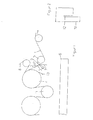
- the fibrous web 1 runs in a dryer section of a paper machine for drying the same usually alternately over heated drying cylinders 4 and evacuated guide rollers 11.
- the fibrous web 1 is guided by at least one dryer 8 of the respective drying group, wherein the fibrous web 1 comes into contact with the drying cylinders 4.
- the fibrous web 1 comes into the region of the water jet cutting device, this being arranged between the drying cylinder 4 and a following guide roll 5.
- This water jet cutting device consists essentially of a nozzle 2, which is arranged above the fibrous web 1 and the water jet is directed approximately perpendicular to the fibrous web 1.
- To support the fibrous web 1 is located on the opposite side of a support plate 3.
- This support plate 3 has a flat and smooth surface and is about 0.5 mm away from the fibrous web 1 in the unloaded state. During cutting, however, the fibrous web 1 is pressed against the support plate 3.
- the support plate 3 according to Figure 2 has a recess 12 for the water jet.
- the support plate 3 also includes a guide member 10, which supports the forwarding of the separated edge strip in the pulper 6 of the dryer section.
- the support plate 3 extends parallel to the run of the fibrous web 1, it offers no possibility for attachment of fibers and other contaminants.
- the separated strip 7 is guided into the arranged below the water jet cutter pulper 6 of the dryer section.
- the collected pulp web remnants can thus be recycled.
- a compressed air or water nozzle 9 blows the strip 7 in the direction of pulper 6 on the drying cylinder 4 adhering fibrous web residues are also from a scraper 13 from the drying cylinder 4th away.
- the fibrous web 1 passes into another area of the paper machine, for example, for brushing or smoothing the fibrous web. 1
- the water jet cutting device is very simple and saves a lot of energy because of the running without a suction edge trim removal taking into account the continuous operation.
Landscapes
- Life Sciences & Earth Sciences (AREA)
- Forests & Forestry (AREA)
- Engineering & Computer Science (AREA)
- Mechanical Engineering (AREA)
- Paper (AREA)
- Perforating, Stamping-Out Or Severing By Means Other Than Cutting (AREA)
- Shovels (AREA)
- Details Of Cutting Devices (AREA)
Description
- Die Erfindung betrifft eine Maschine zur Herstellung und/oder Veredlung der Faserstoffbahn mit zumindest einer Düse, deren Wasserstrahl auf die Faserstoffbahn gerichtet ist, gemäß dem Oberbegriff vom Anspruch 1. Eine derartige Maschine ist aus
EP 1148172 A bekannt. - Wegen des hohen Drucks des Wasserstrahls und der Gewährleistung eines sauberen Schnittes unter Vermeidung von Ein- oder gar Abrissen wird die Faserstoffbahn beim Schneiden mit Wasserstrahl auf der gegenüberliegenden Seite abgestützt. Diese Abstützung erfolgt bei der
US-A1 2001/0004007 durch ein Sieb oder offmals auch durch einen Schneidtisch. Während des Betriebs kommt es zur Verschmutzung der stützenden Flächen durch die Fasern oder die Zusatzstoffe der Faserstoffbahn. Außerdem führt der hohe Druck des Wasserstrahls im Laufe der Zeit auch zum Verschleiß der vom Wasserstrahl getroffenen Flächen. - Gegenüber dem Wasserstrahl besitzt der ebenfalls ansgesprechene Schneidtisch daher oft eine Öffnung zum Abführen und Absaugen der Verunreinigungen und des Wassers. Der abgetrennte Streifen wird dabei unterstützt durch Vakuum in einen Abführtrichter gesaugt. Dies ist insbesondere hinsichtlich der Sauberhaltung des Schneidtisches und der Abführung des Streifens sehr aufwendig.
- Die Aufgabe der Erfindung ist es daher den Aufbau der Schneideinrichtung bei zumindest gleichbleibender Betriebssicherheit zu vereinfachen.
- Die Aufgabe dadurch wird durch die Merkmale des Anspruchs 1 gelöst.
- Der aufwendige Schneidtisch kann damit auf ein Stützblech reduziert werden. Das Stützblech ist sehr einfach aufgebaut und gewährleistet während des Schneidens eine ausreichende Abstützung der Faserstoffbahn im Schneidbereich, wobei das Stützblech eine Aussparung für den Wasserstrahl besitzt, so dass dieser ungehindert hindurchtreten kann.
- Der abgeschnittene Randstreifen fällt nach dem Schneidbereich vom Stützblech herunter. Nach dem Stützblech sollte der Lauf des abgetrennten Streifens von einer Führungseinrichtung vorzugsweise in Form eines Führungsbleches und/oder eines Führungsteiles des Stützblechs und/oder einer Druckluft- und/oder einer Wasserstrahl-Düse beeinflusst werden.
- Um Beschädigungen der Faserstoffbahn zu verhindern und der Anlagerung von Verschmutzungen entgegen zu wirken, sollte das Stützblech eine möglichst ebene Gleitfläche bilden, die etwa parallel zur Faserstoffbahn verläuft.
- Für eine einwandfreie Schnittqualität und eine stabilen Schneidvorgang sollte die Faserstoffbahn zumindest im unbelasteten Zustand durch den Wasserstrahl mit einem Abstand an dem Stützblech entlang laufen. Wegen der ebenen und vorzugsweise glatten Gleitfläche bleibt ein Gleiten der Faserstoffbahn während des Schneidens ohne negative Wirkung. Dabei hat es sich als vorteilhaft erwiesen, wenn der Abstand zwischen Faserstoffbahn und der Gleitfläche des Stützblechs insbesondere im unbelasteten Zustand im Bereich von 0 bis 2 mm, vorzugsweise zwischen 0 und 0,5 mm liegt.
- Im Pulper werden der Ausschuss und Teile der Faserstoffbahn gesammelt und der Faserstoffaufbereitung zur Wiederverwertung zugeführt. Da die Führungseinrichtung die Zuführung des abgetrennten Streifens in den Pulper unterstützt, können aufwendige Saugeinrichtungen zur Führung des abgetrennten Randstreifens eingespart werden.
- Zur Anpassung an bestimmte Betriebsbedingungen sollten die Düse und/oder das Stützblech und/oder die Führungseinrichtung bezüglich ihrer Lage einstellbar gestaltet sein.
- Wegen der bereits erhöhten Festigkeit kann die Wasserstrahl-Schneideinrichtung im freien Zug der Faserstoffbahn, im Bereich der Trockenpartie angeordnet werden. Im freien Zug läuft die Faserstoffbahn ohne sich auf einem Band, einer Walze oder ähnlichem abzustützen.
- Besonders einfach lässt sich die Einbauposition aufgrund der Pulperposition am Ende einer Trockengruppe, vorzugsweise nach dem letzten Trockenzylinder der Trockengruppe realisieren, weshalb die Wasserstrahl-Schneideinrichtung auch dort eingesetzt werden sollte. Nach dem Wegführen des Trockensiebes der Trockengruppe kann so die Wasserstrahl-Schneideinrichtung mit Vorteil zwischen einem, insbesondere dem letzten Trockenzylinder der Trockengruppe und einer folgenden Leitwalze angeordnet sein.
- Nachfolgend soll die Erfindung an einem Ausführungsbeispiel näher erläutert werden. In der beigefügten Zeichnung zeigt:
- Figur 1:
- eine schematische Seitenansicht einer im Einsatz befindlichen Wasserstrahl-Schneideinrichtung und
- Figur 2:
- eine Draufsicht des Stützbleches 3.
- Die Faserstoffbahn 1 läuft in einer Trockenpartie einer Papiermaschine zur Trocknung derselben meist abwechselnd über beheizte Trockenzylinder 4 und besaugte Leitwalzen 11. Dabei wird die Faserstoffbahn 1 von zumindest einem Trockensieb 8 der jeweiligen Trockengruppe geführt, wobei die Faserstoffbahn 1 mit den Trockenzylindern 4 in Kontakt kommt.
- Während der Trocknung nimmt der Feuchtegehalt der Faserstoffbahn 1 ab und die Festigkeit zu. Zur Herstellung sauberer Ränder der Faserstoffbahn 1, kommt die Wasserstrahl-Schneideinrichtung zum Einsatz. Wegen der erhöhten Festigkeit der Faserstoffbahn 1 kann dies im freien Zug der Faserstoffbahn 1 erfolgen.
- Dies ist relativ einfach am Ende einer und insbesondere wie in der Figur 1 gezeigt der letzten Trockengruppe möglich. Nach dem Wegführen des entsprechenden Trockensiebes 8 kommt die Faserstoffbahn 1 in den Bereich der Wasserstrahl-Schneideinrichtung, wobei diese zwischen dem Trockenzylinder 4 und einer folgenden Leitwalze 5 angeordnet ist. Diese Wasserstrahl-Schneideeinrichtung besteht im wesentlichen aus einer Düse 2, die über der Faserstoffbahn 1 angeordnet ist und den Wasserstrahl etwa senkrecht auf die Faserstoffbahn 1 richtet. Zur Abstützung der Faserstoffbahn 1 befindet sich auf der gegenüberliegenden Seite ein Stützblech 3. Dieses Stützblech 3 hat eine ebene und glatte Oberfläche und ist im unbelasteten Zustand etwa 0,5 mm von der Faserstoffbahn 1 entfernt. Während des Schneidens wird die Faserstoffbahn 1 jedoch an das Stützblech 3 gedrückt. Um ein Abspritzen zu verhindern, besitzt das Stützblech 3 gemäß Figur 2 eine Aussparung 12 für den Wasserstrahl. Das Stützblech 3 umfasst außerdem noch ein Führungsteil 10, welches die Weiterleitung des abgetrennten Randstreifens in den Pulper 6 der Trockenpartie unterstützt.
- Da sich das Stützblech 3 parallel zum Lauf der Faserstoffbahn 1 erstreckt bietet es keine Möglichkeit zur Anlagerung von Fasern und anderen Verschmutzungen.
- Nach dem Stützblech 3 wird der abgetrennte Streifen 7 in den unter der Wasserstrahl-Schneideinrichtung angeordneten Pulper 6 der Trockenpartie geführt. Die aufgefangenen Faserstoffbahnreste können so einer Wiederverwertung zugeführt werden.
- Um den Streifen 7 nach dem Stützblech 3 zu führen sind hier Führungseinrichtungen vorgesehen. Nach dem Stützblech 3 bläst eine Druckluft- oder Wasserdüse 9 den Streifen 7 in Richtung Pulper 6. Am Trockenzylinder 4 anhaftenden Faserstoffbahnreste werden außerdem von einem Schaber 13 vom Trockenzylinder 4 entfernt.
- Nach der Wasserstrahl-Schneideinrichtung gelangt die Faserstoffbahn 1 in einen anderen Bereich der Papiermaschine beispielsweise zum Streichen oder Glätten der Faserstoffbahn 1.
- Die Wasserstrahl-Schneideinrichtung ist sehr einfach aufgebaut und spart wegen der ohne eine Saugvorrichtung auskommenden Randstreifenabführung unter Berücksichtigung des Dauerbetriebs sehr viel Energie.
Claims (8)
- Maschine zur Herstellung und/oder Veredlung einer Faserstoffbahn (1) mit einer Wasserstrahl-Schneideinrichtung zum Trennen eines Streifens (7) von einer laufenden Papier-, Karton-, Tissue- oder einer anderen Faserstoffbahn (1) mit zumindest einer Düse (2), deren Wasserstrahl auf die Faserstoffbahn (1) gerichtet ist, wobei die Wasserstrahl-Schneideinrichtung im Bereich der Trockenpartie im freien Zug der Faserstoffbahn (1) angeordnet ist,
dadurch gekennzeichnet,
dass die Wasserstrahl-Schneideinrichtung etwa über einem Pulper (6) zum Auffangen des abgetrennten Streifens (7) der Faserstoffbahn (1) angeordnet ist und ohne Vakuumsysteme bei der Abführung des abgetrennten Streifens (7) auskommt und wobei in einem Schneidbereich auf der der Düse (2) gegenüberliegenden Seite der Faserstoffbahn (1) ein Stützblech angeordnet ist. - Maschine nach Anspruch 1,
dadurch gekennzeichnet, dass
das Stützblech (3) eine Gleitfläche bildet, die etwa parallel zur Faserstoffbahn (1) verläuft. - Maschine nach einem der vorhergehenden Ansprüche,
dadurch gekennzeichnet, dass
die Faserstoffbahn (1) zumindest im unbelasteten Zustand durch den Wasserstrahl mit einem Abstand an dem Stützblech (3) entlang läuft. - Maschine nach Anspruch 3,
dadurch gekennzeichnet, dass
der Abstand zwischen Faserstoffbahn (1) und der Gleitfläche des Stützblechs (3) im Bereich von 0 bis 2 mm, vorzugsweise zwischen 0 und 0,5 mm liegt. - Maschine nach einem der vorhergehenden Ansprüche,
dadurch gekennzeichnet, dass
der Lauf des abgetrennten Streifens (7) nach dem Stützblech (3) von einer Führungseinrichtung vorzugsweise in Form eines Führungsbleches und/oder eines Führungsteiles (10) des Stützbleches (3) und/oder einer Druckluftund/oder einer Wasserstrahl-Düse (9) beeinflusst wird. - Maschine nach einem der vorhergehenden Ansprüche,
dadurch gekennzeichnet, dass
die Düse (2) und/oder das Stützblech (3) und/oder die Führungseinrichtung in ihrer Lage einstellbar sind. - Maschine nach Anspruch 6,
dadurch gekennzeichnet, dass
die Wasserstrahl-Schneideinrichtung am Ende einer Trockengruppe, vorzugsweise nach dem letzten Trockenzylinder (4) der Trockengruppe angeordnet ist. - Maschine nach Anspruch 7,
dadurch gekennzeichnet, dass
die Wasserstrahl-Schneideinrichtung zwischen einem Trockenzylinder (4) und einer folgenden Leitwalze (5) angeordnet ist.
Applications Claiming Priority (2)
| Application Number | Priority Date | Filing Date | Title |
|---|---|---|---|
| DE2002117723 DE10217723A1 (de) | 2002-04-20 | 2002-04-20 | Wasserstrahl-Schneideinrichtung |
| DE10217723 | 2002-04-20 |
Publications (3)
| Publication Number | Publication Date |
|---|---|
| EP1354677A2 EP1354677A2 (de) | 2003-10-22 |
| EP1354677A3 EP1354677A3 (de) | 2005-02-23 |
| EP1354677B1 true EP1354677B1 (de) | 2007-08-22 |
Family
ID=28458947
Family Applications (1)
| Application Number | Title | Priority Date | Filing Date |
|---|---|---|---|
| EP20030001815 Expired - Lifetime EP1354677B1 (de) | 2002-04-20 | 2003-01-29 | Maschine mit Wasserstrahl-Schneideinrichtung |
Country Status (5)
| Country | Link |
|---|---|
| US (1) | US7166194B2 (de) |
| EP (1) | EP1354677B1 (de) |
| AT (1) | ATE370822T1 (de) |
| CA (1) | CA2425682A1 (de) |
| DE (2) | DE10217723A1 (de) |
Families Citing this family (9)
| Publication number | Priority date | Publication date | Assignee | Title |
|---|---|---|---|---|
| DE10315703A1 (de) * | 2003-04-07 | 2004-10-21 | Voith Paper Patent Gmbh | Wasserstrahlschneiden |
| FI116664B (fi) | 2004-06-18 | 2006-01-31 | Metso Paper Inc | Menetelmä ja laite paperi- tai kartonkikoneessa |
| DE102009056625B9 (de) | 2009-12-02 | 2011-05-12 | Paprima Industries Inc., Dorval | Verlängerungseinrichtung für einen Luftleitkasten |
| US20110240706A1 (en) * | 2010-03-30 | 2011-10-06 | Brian Christopher Schwamberger | Web diverting apparatus |
| US9217225B2 (en) | 2012-02-28 | 2015-12-22 | Paprima Industries Inc. | Paper manufacturing |
| US8968519B2 (en) * | 2013-03-14 | 2015-03-03 | Georgia-Pacific Consumer Products Lp | Sheet edge trimming and removal from a structured paper fabric |
| EP3020520B1 (de) * | 2014-11-14 | 2018-01-03 | HP Scitex Ltd | Flüssigstickstoffstrahlstromverarbeitung von Papier, Kartons oder Pappe |
| FR3085974B1 (fr) | 2018-09-14 | 2020-12-18 | Oberthur Fiduciaire Sas | Procede de fabrication d'un materiau en feuille, machine, materiau en feuille et document de securite correspondants |
| FI131085B1 (en) | 2022-02-17 | 2024-09-17 | Valmet Tech Oy | Method and system for the production of fiber webs |
Family Cites Families (14)
| Publication number | Priority date | Publication date | Assignee | Title |
|---|---|---|---|---|
| US3891157A (en) * | 1973-06-04 | 1975-06-24 | Beloit Corp | Slitting mechanism for winder |
| DE2656242C2 (de) * | 1976-12-11 | 1978-12-21 | J.M. Voith Gmbh, 7920 Heidenheim | Vorrichtung zum Trennen einer Faserbahn |
| SE447584B (sv) * | 1983-06-01 | 1986-11-24 | Valmet Kmw Ab | Forfarande och anordning for att senka energiatgangen vid torkning av en pappersbana |
| FI83249C (fi) * | 1988-03-15 | 1991-06-10 | Valmet Paper Machinery Inc | Kalandreringsanlaeggning och -foerfarande. |
| WO1991003359A1 (en) * | 1989-09-08 | 1991-03-21 | Fibron Machine Corp. | An apparatus for cutting a moving paper sheet by means of a water jet |
| FI84742C (fi) * | 1990-02-22 | 1992-01-10 | Valmet Paper Machinery Inc | Foerfarande och anordning vid skaerning av spetsdragningsbandet av en pappersbana. |
| US5644962A (en) * | 1991-11-19 | 1997-07-08 | Valmet Corporation | Dryer section of a paper or board machine including an arrangement for cutting a leader of the web |
| FI98346C (fi) * | 1994-03-31 | 1997-06-10 | Enfoplan Oy | Menetelmä ja laitteisto liikkuvan paperirainan reunan leikkaamiseksi |
| US6327948B1 (en) * | 1995-09-26 | 2001-12-11 | Esko Tuori | Method and apparatus for cutting the edge of a moving paper web |
| FI104644B (fi) * | 1998-08-17 | 2000-03-15 | Valmet Corp | Menetelmä ja laite paperikoneella rainan siirtämiseksi formeriosalta puristinosalle |
| US6358367B1 (en) * | 2000-02-01 | 2002-03-19 | Voith Sulzer Paper Technology North America, Inc. | Pulping system for a paper machine |
| DE10016754A1 (de) * | 2000-04-04 | 2001-10-11 | Voith Paper Patent Gmbh | Papiermaschine |
| DE10017288A1 (de) * | 2000-04-06 | 2001-10-31 | Koenig & Bauer Ag | Vorrichtung zum Schneiden von Papierbahnen |
| FI115203B (fi) * | 2000-10-02 | 2005-03-31 | Metso Paper Inc | Laitteisto erityisesti paperiradan leikkaamiseksi vesisuihkulla |
-
2002
- 2002-04-20 DE DE2002117723 patent/DE10217723A1/de not_active Withdrawn
-
2003
- 2003-01-29 EP EP20030001815 patent/EP1354677B1/de not_active Expired - Lifetime
- 2003-01-29 AT AT03001815T patent/ATE370822T1/de active
- 2003-01-29 DE DE50307989T patent/DE50307989D1/de not_active Expired - Lifetime
- 2003-04-16 CA CA 2425682 patent/CA2425682A1/en not_active Abandoned
- 2003-04-19 US US10/418,332 patent/US7166194B2/en not_active Expired - Fee Related
Also Published As
| Publication number | Publication date |
|---|---|
| EP1354677A3 (de) | 2005-02-23 |
| DE50307989D1 (de) | 2007-10-04 |
| EP1354677A2 (de) | 2003-10-22 |
| US7166194B2 (en) | 2007-01-23 |
| ATE370822T1 (de) | 2007-09-15 |
| DE10217723A1 (de) | 2003-10-30 |
| US20030196531A1 (en) | 2003-10-23 |
| CA2425682A1 (en) | 2003-10-20 |
Similar Documents
| Publication | Publication Date | Title |
|---|---|---|
| EP1245729B1 (de) | Vorrichtung zum Überführen einer Bahn | |
| EP0639668A2 (de) | Trockenpartie | |
| DE4327601C1 (de) | Vorrichtung zum Reinigen eines umlaufenden Siebes | |
| EP1354677B1 (de) | Maschine mit Wasserstrahl-Schneideinrichtung | |
| DE69327151T2 (de) | Vorrichtung zum Formierung von mehrschichtigem Papier | |
| EP0522093B1 (de) | Verfahren und vorrichtung zum reinigen eines umlaufenden papiermaschinensiebes | |
| DE3400939C2 (de) | ||
| DE69304469T2 (de) | Papiermaschine mit einem Einfädelsystem in der Presspartie | |
| DE19882574C2 (de) | Verfahren und Vorrichtung zur Trocknung einer Stoffbahn | |
| DE3336184A1 (de) | Vorrichtung zum reinigen rotierender walzen von textilmaschinen | |
| DE10024296B4 (de) | Maschine zur Herstellung einer Materialbahn | |
| DE10140800A1 (de) | Vorrichtung zur Behandlung einer Faserstoffbahn | |
| DE102019116602A1 (de) | Maschine zur herstellung einer faserstoffbahn | |
| EP1478806B1 (de) | Glättvorrichtung | |
| DE19636791A1 (de) | Verfahren und Vorrichtung zur Entfernung von Papierbahnresten von einem Band | |
| DE4328554A1 (de) | Trockenpartie | |
| WO2005113890A1 (de) | Reinigungsvorrichtung | |
| DE3731541C2 (de) | Verfahren und Vorrichtung zur stabilisierten Führung einer bewegten Materialbahn | |
| DE4108167A1 (de) | Einrichtung zum entfernen von ausschuss | |
| DE9103056U1 (de) | Einrichtung zum Entfernen von Ausschuß | |
| DE102009027608A1 (de) | Trockenpartie | |
| DE102010038875A1 (de) | Vorrichtung und Verfahren zur Herstellung einer Materialbahn | |
| DE102004042637A1 (de) | Pressvorrichtung für eine Papiermaschine | |
| WO1995020068A1 (de) | Zugfreie bahnüberführung in einer pressenpartie | |
| DE10233797A1 (de) | Reinigungs- und Entwässerungsvorrichtung |
Legal Events
| Date | Code | Title | Description |
|---|---|---|---|
| PUAI | Public reference made under article 153(3) epc to a published international application that has entered the european phase |
Free format text: ORIGINAL CODE: 0009012 |
|
| AK | Designated contracting states |
Kind code of ref document: A2 Designated state(s): AT BE BG CH CY CZ DE DK EE ES FI FR GB GR HU IE IT LI LU MC NL PT SE SI SK TR |
|
| AX | Request for extension of the european patent |
Extension state: AL LT LV MK RO |
|
| PUAL | Search report despatched |
Free format text: ORIGINAL CODE: 0009013 |
|
| AK | Designated contracting states |
Kind code of ref document: A3 Designated state(s): AT BE BG CH CY CZ DE DK EE ES FI FR GB GR HU IE IT LI LU MC NL PT SE SI SK TR |
|
| AX | Request for extension of the european patent |
Extension state: AL LT LV MK RO |
|
| 17P | Request for examination filed |
Effective date: 20050823 |
|
| AKX | Designation fees paid |
Designated state(s): AT DE FI SE |
|
| 17Q | First examination report despatched |
Effective date: 20060306 |
|
| RAP1 | Party data changed (applicant data changed or rights of an application transferred) |
Owner name: VOITH PATENT GMBH |
|
| GRAP | Despatch of communication of intention to grant a patent |
Free format text: ORIGINAL CODE: EPIDOSNIGR1 |
|
| RTI1 | Title (correction) |
Free format text: MACHINE WITH WATER-JET CUTTING DEVICE |
|
| RIN1 | Information on inventor provided before grant (corrected) |
Inventor name: PFIFFERLING, RALF Inventor name: SOLLINGER, MICHAEL, DR. Inventor name: STRAUB, KARLHEINZ |
|
| GRAS | Grant fee paid |
Free format text: ORIGINAL CODE: EPIDOSNIGR3 |
|
| GRAA | (expected) grant |
Free format text: ORIGINAL CODE: 0009210 |
|
| AK | Designated contracting states |
Kind code of ref document: B1 Designated state(s): AT DE FI SE |
|
| REF | Corresponds to: |
Ref document number: 50307989 Country of ref document: DE Date of ref document: 20071004 Kind code of ref document: P |
|
| REG | Reference to a national code |
Ref country code: SE Ref legal event code: TRGR |
|
| PLBE | No opposition filed within time limit |
Free format text: ORIGINAL CODE: 0009261 |
|
| STAA | Information on the status of an ep patent application or granted ep patent |
Free format text: STATUS: NO OPPOSITION FILED WITHIN TIME LIMIT |
|
| 26N | No opposition filed |
Effective date: 20080526 |
|
| PGFP | Annual fee paid to national office [announced via postgrant information from national office to epo] |
Ref country code: SE Payment date: 20110113 Year of fee payment: 9 |
|
| PGFP | Annual fee paid to national office [announced via postgrant information from national office to epo] |
Ref country code: DE Payment date: 20120123 Year of fee payment: 10 |
|
| PGFP | Annual fee paid to national office [announced via postgrant information from national office to epo] |
Ref country code: FI Payment date: 20120625 Year of fee payment: 10 |
|
| REG | Reference to a national code |
Ref country code: SE Ref legal event code: EUG |
|
| PG25 | Lapsed in a contracting state [announced via postgrant information from national office to epo] |
Ref country code: SE Free format text: LAPSE BECAUSE OF NON-PAYMENT OF DUE FEES Effective date: 20120130 |
|
| PGFP | Annual fee paid to national office [announced via postgrant information from national office to epo] |
Ref country code: AT Payment date: 20120622 Year of fee payment: 10 |
|
| REG | Reference to a national code |
Ref country code: AT Ref legal event code: MM01 Ref document number: 370822 Country of ref document: AT Kind code of ref document: T Effective date: 20130131 |
|
| PG25 | Lapsed in a contracting state [announced via postgrant information from national office to epo] |
Ref country code: DE Free format text: LAPSE BECAUSE OF NON-PAYMENT OF DUE FEES Effective date: 20130801 Ref country code: FI Free format text: LAPSE BECAUSE OF NON-PAYMENT OF DUE FEES Effective date: 20130129 Ref country code: AT Free format text: LAPSE BECAUSE OF NON-PAYMENT OF DUE FEES Effective date: 20130131 |
|
| REG | Reference to a national code |
Ref country code: DE Ref legal event code: R119 Ref document number: 50307989 Country of ref document: DE Effective date: 20130801 |