EP1353034B1 - Construction de cadre pour porte coulissante - Google Patents
Construction de cadre pour porte coulissante Download PDFInfo
- Publication number
- EP1353034B1 EP1353034B1 EP03405238A EP03405238A EP1353034B1 EP 1353034 B1 EP1353034 B1 EP 1353034B1 EP 03405238 A EP03405238 A EP 03405238A EP 03405238 A EP03405238 A EP 03405238A EP 1353034 B1 EP1353034 B1 EP 1353034B1
- Authority
- EP
- European Patent Office
- Prior art keywords
- frame
- insulating body
- frame part
- accommodating
- main frame
- Prior art date
- Legal status (The legal status is an assumption and is not a legal conclusion. Google has not performed a legal analysis and makes no representation as to the accuracy of the status listed.)
- Expired - Lifetime
Links
Images


Classifications
-
- E—FIXED CONSTRUCTIONS
- E06—DOORS, WINDOWS, SHUTTERS, OR ROLLER BLINDS IN GENERAL; LADDERS
- E06B—FIXED OR MOVABLE CLOSURES FOR OPENINGS IN BUILDINGS, VEHICLES, FENCES OR LIKE ENCLOSURES IN GENERAL, e.g. DOORS, WINDOWS, BLINDS, GATES
- E06B3/00—Window sashes, door leaves, or like elements for closing wall or like openings; Layout of fixed or moving closures, e.g. windows in wall or like openings; Features of rigidly-mounted outer frames relating to the mounting of wing frames
- E06B3/04—Wing frames not characterised by the manner of movement
- E06B3/263—Frames with special provision for insulation
- E06B3/26347—Frames with special provision for insulation specially adapted for sliding doors or windows
Definitions
- the invention relates to a frame construction of a sliding door or sliding window according to the preamble of patent claim 1.
- a frame construction is in EP-A-0'080'870 disclosed.
- a main frame made of aluminum two plastic receiving profiles are arranged for receiving one door leaf each.
- the receiving profile of the sliding door is provided with a carriage, which is slidably guided in the main frame.
- the two receiving profiles are separated by a separating element which projects between the receiving profiles and which is integrally formed on the main frame. This separating element also serves to receive sealing brushes, which rest in a sliding manner on the displaceable receiving profile.
- the main frame is designed to be continuous from outside to inside. Thus, it forms a cold bridge between the outside and inside of the window or the door.
- a construction which has a two-part main frame to avoid such cold bridges.
- the inner and the outer part of the frame are separated by an insulating body.
- the receiving profile of the sliding door is arranged within the outer frame part.
- sealing brushes are arranged on both sides, which rest in a sliding manner on the sliding receiving profile.
- the two frame parts are U-shaped. However, since a leg of the respective outer part protrudes from the cold to the warm area, it comes at this point to condensation.
- the receiving profiles of the insulating glass are not insulated and therefore form a continuous cold bridge.
- EP-A-1'101'894 a frame construction for sliding doors, in which each door is held in an L-shaped inner frame.
- the legs of the L-shaped frame extend in the lower horizontal direction and in a lateral vertical direction.
- the two free sides of the door leaf run in an outer frame, which has in the region of these two sides an inner and an outer frame part, which is separated by an insulating body.
- the windows are held along these two sides in receiving profiles, which are laterally provided with brushes. These inner brushes slide along when moving the door along of the insulation body.
- This construction has the disadvantage that the free window area is limited by the L-shaped inner frame.
- the construction is also only suitable for double-leaf doors and can not be used for multi-leaf doors.
- the construction has a relatively high threshold in the lower region due to the lower insulating body. Since this frame construction has differently constructed sides, it is relatively expensive to manufacture and expensive to assemble.
- the BE 1002537 A3 discloses a frame construction for sliding windows, comprising two interconnected by an insulating body rails.
- the two metal rails consisting of insulating rails project above the rails and serve as a system for seals.
- the sliding doors are each supported on the outer leg, which makes a sunken installation of the sliding door in the floor and of course in the ceiling impossible.
- the two guide rails are only partially isolated from each other and the central web, which separates the two runways from each other, consists of metal and thus forms a cold bridge in the longitudinal direction.
- the frame is formed in three parts, wherein the first, outer and the second inner frame part are completely separated from each other at least along the leadership of the carriage by an insulating body.
- Inner sealing elements are slidably between a receiving profile for a door or window sash and a middle frame part.
- the insulating body forms the third part, in the second case, the middle frame part.
- the inner sealing elements are on the middle frame part held.
- the middle frame part is preferably completely thermally separated from the first and the second frame part.
- the middle frame part is also interrupted by transverse to its longitudinal extent of a further sealing part, preferably a brush.
- the arrangement of the inner sealing elements or the further sealing part prevents cold bridges between the inner and the outer frame part. In addition, the formation of condensation is avoided.
- the frame construction can be formed without threshold in the lower area.
- the free window area is maximized. Since the identical parts for the inner, outer and middle frame parts as well as for the insulating body can be used on all four sides of the frame construction, the production and assembly costs are minimized.
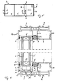
- FIG. 1 shows a sliding door S with a frame structure R, in which a fixed door F and a sliding door T are arranged according to a first embodiment. It is also possible to arrange both door slideable and / or more than two door leaves in insert the sliding door.
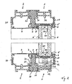
- the inventive frame construction R is in the Figures 2 and 3 better visible.
- the main frame is divided into a first frame part 1 and a second frame part 2.
- the first frame part 1 is here outside, the second frame part 2 arranged inside.
- the arrangement can also be reversed.
- the outer and the inner frame part 1,2 are formed by four profile elements, which each form a longitudinal side of the frame structure.
- the individual profile elements of a frame part 1,2 are identical except for their length. In FIG. 2 the lower and upper profile elements are visible, in FIG. 3 the right and left.
- the following is spoken by frame part 1, 2, wherein in each case a corresponding profile element is meant.
- the first frame part 1 or the corresponding profile element has a substantially U-shaped cross-section.
- an outer leg 10 of the frame part 1 is formed longer than an inner leg 11.
- the two legs are connected via a web 12 with each other.
- the inner frame part 2 or the corresponding profile element is preferably constructed identically as the outer frame part 1. This allows the production costs to be minimized. It is arranged mirror-symmetrically to the first frame part 1, so that its long leg 20 is directed inwards and its short leg 21 outwards.
- an insulating body 7 arranged to prevent cold spots. It is located next to a plane defined by the far-edge or door surface. This insulating body 7 extends on all four sides over the entire length of the frame construction. It is a profile element, which is preferably made of a heat-insulating plastic, foam or other suitable insulation material. He is also preferably formed mirror-symmetrical.
- a head 70 which tapers towards the center of the insulating body towards a neck 71.
- this end is located at the top, bottom, right or left.
- the short legs 11, 21 of the inner and outer frame part 1, 2 have a matching shape, so that they are held in a form-fitting manner on the insulating body 7.
- the positive connection increases the stability. In this case, these short legs 11, 21 preferably extend at most up to the average height of the insulating body. 7
- a middle frame part 3 of the main frame is attached. This too is preferably symmetrical. It also has a substantially U-shaped cross-section, wherein its web is extended on both sides and projects outwardly and the legs are formed of equal length, being bent in an L-shape outwards. The legs are designed so short that the central frame part 3 is at least completely separated from the inner and outer frame part 1, 2.
- the door leaf of the fixed as well as the sliding door F, T is arranged in a receiving profile 5.
- This receiving profile 5 in turn consists of four extending along the sides of the frame construction individual profiles, which are connected to each other in a known manner. Usually they are simply glued to the glass of the respective door leaf.
- FIG. 2 the upper and lower receiving profile 5 is shown in the FIG. 3 the left and right of each door F, T. The following is again on first FIG. 2 received.
- the receiving profile 5 has a U-shaped, preferably symmetrical cross section.
- each door leaf F, T has a double glazing, so that in each receiving profile 5 an outer glass pane 6 and an inner glass pane 6 'are fixed, which are held by a glass edge composite 60 at a distance to each other.
- the receiving profile 5 has a web, which is preferably penetrated by a heat-insulating insert member 50. So here again a cold bridge is broken from the outside to the inside insulating.
- the frame part of the fixed door leaf F here the inner frame part 2 is covered in its area projecting the door leaf with a covering profile 9, in particular made of aluminum. This prevents dirt from entering the upwardly open profile of the frame part 2. If both wings are designed to be displaceable, so unnecessary the cover profile 9.
- the lower receiving profile 5 of the sliding door T is arranged on a carriage 4.
- This carriage 4 has at least one impeller 41, which is mounted guided on a survey of the lower web 12 of the outer frame part 1. Furthermore, it is guided by ball bearings 42 arranged laterally of the running wheel 41.
- sealing elements 8, 8 'slidably Between the sliding receiving profile 5 and the fixed position frame construction are sealing elements 8, 8 'slidably. These sealing elements 8, 8 'preferably extend over the entire length of the receiving profile 5 and thus the door surface. In the example shown here, the sealing elements 8, 8 'sealing lips which slidably rest on the receiving profile 5 and are held with a thickened head in corresponding receptacles of the frame structure. However, it is also possible to use brushes or other shaped sealing elements.
- the sealing lips have the advantage that they absorb less dirt than the brushes.
- they are made of a suitable plastic or rubber and have an integrated wire. This wire reinforces the sealing lips and prevents them from being carried along by the sliding door leaf. The seal is thus guaranteed even after prolonged use of the sliding door.
- These sealing elements with integrated wire can also be used in other frame designs of sliding doors or sliding windows.
- the thickened head of the outer Sealing member 8 held in a formed by the outer leg 10 of the outer frame part 1 receiving groove.
- the inner sealing element 8 ' is held with its thickened head in a receiving groove of the central frame part 3, which is formed by the L-shaped bent leg and the projecting web.
- the inner frame part 2 is exactly the opposite. Brushes are used, they are preferably also held in the frame construction.
- sealing elements 8, 8 At the upper receiving profiles 5 of the sliding door T are also such sealing elements 8, 8 'slidably. Again, these are held in the parts of the frame structure described above.
- the receiving profile 5 of the sliding door T is held on one side in a handle unit 5 ', on which on one, here on both sides of an operating handle G is arranged.
- the handle unit 5 ' consists of two profile elements 51 and at least one, here two connecting these isolation webs 52.
- the sealing elements 8, 8' not on the receiving profiles 5, but on the handle unit 5 'sealingly.
- FIG. 3 are the fixed sash F and the transition region B from the fixed to the sliding sash F, T visible.
- the fixed sash F is also held on all four sides in a receiving profile, which is sealed with sealing elements, preferably with the above-described sealing lips 8, 8 'relative to the frame construction.
- the transition region B consists of two symmetrically formed, identically shaped connecting pieces V, V 'in the form of profile elements.
- Each connecting piece V forms a fixed receptacle for the receiving profile 5 of the fixed or sliding door F, T. It also has a direction to the other door towards V-shaped groove, whose outer leg directed towards the outside to the other door receiving groove for Seal member 8, 8 'forms.
- the outer legs of the respective V-shaped groove project into the V-shaped groove of the other connector V, V '.
- the conical design allows a sufficient contact pressure.
- the sealing elements 8, 8 ' abut against the inner legs of the V-shaped grooves. As a result, optimal heat insulation is ensured by the sealing lip and the labyrinth-like transition region.
- the middle frame part 3 is not continuous, but is interrupted by a further sealing part 30.
- This sealing member 30 is preferably a sealing brush whose bristles are directed towards the surface of the door leaf. The interruption is located between the fixed and the sliding door T, F, when they are in their closed position. This ensures that no parts protrude from the cold into the warm area and thus do not create cold spots.
- FIGS. 5 to 9 a second embodiment is shown.
- the same parts are provided with the same reference numerals and are therefore not detailed again here.
- the outer and inner sealing elements 8, 8 ' are here now preferably formed by brushing. However, they can also be the sealing lips described above.
- the inner sealing element 8 ' is now not held in the middle frame part 3 but between insulation body 7 and middle frame part 3. These two elements are designed to form a suitable receptacle, here a groove.
- the insulating body 7 and the middle frame part 3 has a different cross-sectional shape than in the first embodiment.
- the insulation body 7 is hollow in this example.
- On the outer side surfaces of the arms 74 can also be the inner sealing element 8 'attach in a simple manner.
- the inner sealing element 8 ' is held on the insulating body 7, which has a corresponding receiving groove or other fastening means.
- the insulating body 7 can still be covered with a middle frame part 3, in particular made of metal.
- FIG. 6 also recognizable is the carriage 4.
- this survey is also formed by a profile part 13, which is arranged in the web 12 and which has a side wall 13 'as a privacy shield and demarcation with respect to the insulating body 7.
- FIG. 7 is a section through the fixed sash F shown, wherein the inner and outer sealing elements 8, 8 'are not shown.
- the structure corresponds to the section according to AA and is therefore not repeated.
- FIG. 8 shows the section through the sliding window or door T. Again, the structure is identical again.
- FIG. 9 shows the transition region B between fixed and sliding window sash.
- connecting pieces V, V ' which have receiving grooves for the inner and outer sealing elements 8, 8'.
- the inner and outer sealing elements 8, 8 ' are not on the other connecting pieces V, V', but contact the receiving profiles 5.
- the leg L of the connecting piece V, V ' is correspondingly shorter than in the first embodiment. As a result, the insulation is increased, since even here no more cold bridges can arise.
- the frame construction according to the invention has improved thermal insulation and can nevertheless be made relatively narrow. By using as possible Symmetrical items can also minimize manufacturing costs.
Claims (9)
- Construction de cadre d'une porte coulissante ou d'une fenêtre coulissante, comprenantun cadre principal,un chariot ( 4 ) pour recevoir un battant coulissant de porte ( T ) ou de fenêtre, le chariot ( 4 ) étant guidé à coulissement dans le cadre principal,des profilés récepteurs ( 5 ) pour recevoir les battants de porte ( F, T ) ou de fenêtre,des éléments d'étanchéité extérieurs ( 8 ) qui s'appliquent en glissement entre les profilés récepteurs ( 5 ) et une région extérieure du cadre principal,des éléments d'étanchéité intérieurs ( 8' ) qui s'appliquent en glissement entre les profilés récepteurs (5) et une région intérieure du cadre principal,et un corps isolant (7),le cadre principal comportant une partie ( 1 ) extérieure et une partie ( 2 ) intérieure de cadre,
la partie ( 1 ) extérieure et la partie ( 2 ) intérieure de cadre étant totalement séparées l'une de l'autre par le corps isolant ( 7 ) au moins le long du guidage du chariot ( 4 ),
et l'élément d'étanchéité intérieur ( 8' ) s'appliquant contre le corps isolant ( 7 ) ou contre une partie ( 3 ) centrale du cadre principal qui est séparée de la partie ( 1 ) extérieure et de la partie ( 2 ) intérieure de cadre,
caractérisée en ce qu'au moins la partie ( 3 ) centrale de cadre, posée sur le corps isolant ( 7 ) sur la portion inférieure de cadre s'étendant horizontalement, est réalisée en métal et n'est pas continue. - Construction de cadre suivant la revendication 1, caractérisée en ce que la partie ( 3 ) de cadre est interrompue par une partie d'étanchéité ( 30 ).
- Construction de cadre suivant la revendication 1 ou 2, caractérisée en ce que la partie (3) centrale de cadre est emboîtée à complémentarité de forme sur le corps isolant ( 7 ).
- Construction de cadre suivant la revendication 2, caractérisée en ce que la partie d'étanchéité ( 30 ) est une brosse d'étanchéité dont les soies sont dirigées vers la surface du battant de porte.
- Construction de cadre suivant l'une des revendications 1 à 4, caractérisée en ce que la partie ( 1 ) extérieure et la partie ( 2 ) intérieure de cadre sont totalement séparées l'une de l'autre par le corps isolant ( 7 ) sur les quatre côtés du cadre principal, en ce que des éléments d'étanchéité intérieurs ( 8' ) sont prévus sur chaque côté du cadre principal, éléments qui s'appliquent contre une partie ( 3 ) centrale du cadre principal qui est séparée de la partie ( 1 ) extérieure et de la partie ( 2 ) intérieure de cadre, et en ce que les quatre côtés du cadre principal comportent des parties de cadre, y compris le cas échéant des parties centrales de cadre, et des corps isolants de conception identique.
- Construction de cadre suivant l'une des revendications 1 à 5, caractérisée en ce que l'élément d'étanchéité intérieur ( 8' ) est maintenu dans un logement de la partie ( 3 ) centrale de la construction de cadre qui est formé par une branche recourbée en L et une partie de liaison dépassante.
- Construction de cadre suivant l'une des revendications 1 à 6, caractérisée en ce que le profilé récepteur ( 5 ) comporte une partie de liaison qui est traversée par un élément d'insertion ( 50 ) calorifuge, qui interrompt par son action isolante un pont thermique de l'extérieur vers l'intérieur.
- Construction de cadre suivant l'une des revendications 1 à 7, caractérisée en ce que le chariot ( 4 ) comporte au moins un galet ( 41 ) doté de part et d'autre d'un guide latéral ( 42 ) à roulement à billes.
- Construction de cadre suivant l'une des revendications 1 à 8, caractérisée en ce que des éléments d'étanchéité extérieurs ( 8 ) sont maintenus dans une branche extérieure d'une partie de cadre ( 12 ) et s'appliquent en glissement contre les profilés récepteurs ( 5 ), et en ce que des éléments d'étanchéité intérieurs ( 8' ) sont maintenus dans le corps isolant ( 7 ) ou dans la partie ( 3 ) centrale de cadre ou entre le corps isolant ( 7 ) et la partie ( 3 ) centrale de cadre, et s'appliquent en glissement contre les profilés récepteurs ( 5 ).
Applications Claiming Priority (2)
| Application Number | Priority Date | Filing Date | Title |
|---|---|---|---|
| CH6052002 | 2002-04-10 | ||
| CH6052002 | 2002-04-10 |
Publications (3)
| Publication Number | Publication Date |
|---|---|
| EP1353034A2 EP1353034A2 (fr) | 2003-10-15 |
| EP1353034A3 EP1353034A3 (fr) | 2004-09-15 |
| EP1353034B1 true EP1353034B1 (fr) | 2008-07-30 |
Family
ID=28048301
Family Applications (1)
| Application Number | Title | Priority Date | Filing Date |
|---|---|---|---|
| EP03405238A Expired - Lifetime EP1353034B1 (fr) | 2002-04-10 | 2003-04-08 | Construction de cadre pour porte coulissante |
Country Status (6)
| Country | Link |
|---|---|
| EP (1) | EP1353034B1 (fr) |
| AT (1) | ATE403057T1 (fr) |
| DE (1) | DE50310220D1 (fr) |
| DK (1) | DK1353034T3 (fr) |
| ES (1) | ES2311684T3 (fr) |
| PT (1) | PT1353034E (fr) |
Cited By (4)
| Publication number | Priority date | Publication date | Assignee | Title |
|---|---|---|---|---|
| US8286396B2 (en) | 2006-12-22 | 2012-10-16 | Technoform Bautec Holding Gmbh | Plastic profile for window, door and facade elements |
| EP2400099B1 (fr) | 2010-06-25 | 2016-07-13 | DORMA Deutschland GmbH | Installation de battant à isolation thermique |
| EP3865644A1 (fr) | 2020-02-17 | 2021-08-18 | Seu Plastics One Man L.L.C. | Mécanisme de verrouillage pour cadre encastré caché |
| DE102010023607C5 (de) | 2010-06-14 | 2022-06-23 | Landert Group Ag | Thermisch isoliertes Profil für Schiebetüren |
Families Citing this family (14)
| Publication number | Priority date | Publication date | Assignee | Title |
|---|---|---|---|---|
| FR2861794B1 (fr) * | 2003-10-30 | 2006-02-03 | Daniel Vinatier | Menuiserie pour vantaux coulissants comportant un masque de protection thermique de l'encadrement du vitrage. |
| DE10353822A1 (de) * | 2003-11-18 | 2005-06-23 | Eduard Hueck Gmbh & Co Kg | Schwellenprofil für eine Schiebetür oder ein Schiebefenster |
| US7520093B2 (en) | 2004-01-13 | 2009-04-21 | Beat Guhl | Frame construction of a sliding door |
| FR2912175B1 (fr) * | 2007-02-02 | 2009-04-17 | Norsk Hydro As | Chassis de porte ou fenetre a serrure comportant un cadre et au moins un ouvrant coulissant. |
| ITBO20070243A1 (it) * | 2007-04-03 | 2008-10-04 | Gsg Int Spa | Accessorio per profilati per serramenti scorrevoli. |
| EP2281990A1 (fr) | 2009-06-29 | 2011-02-09 | Orchidées Constructions S.A. | Fenêtre ou porte vitrée coulissante |
| IT1394972B1 (it) * | 2009-07-31 | 2012-08-07 | Gsg Int Spa | Infisso scorrevole rinforzato. |
| CN101886510B (zh) * | 2010-07-19 | 2011-09-07 | 浙江瑞明节能门窗股份有限公司 | 一种铝合金推拉节能门窗系统 |
| AT511726B1 (de) | 2011-07-15 | 2013-05-15 | Alfons Oberhofer | Vorrichtung zum verschieben eines schiebeelements |
| FR2981976B1 (fr) * | 2011-11-02 | 2015-01-02 | Norsk Hydro As | Fermeture coulissante de baie de construction |
| CN104005664A (zh) * | 2014-05-12 | 2014-08-27 | 安徽同曦金鹏铝业有限公司 | 隔热推拉门封边盖板型材 |
| EP3034767B1 (fr) | 2014-12-18 | 2017-11-01 | dormakaba Deutschland GmbH | Système de paroi coulissante |
| US20190145155A1 (en) | 2016-05-03 | 2019-05-16 | Technoform Bautec Holding Gmbh | Sash for a sliding window or a sliding door and method for providing an untreated metal surface in such a sash |
| FR3095001B1 (fr) * | 2019-04-11 | 2021-04-30 | Titime | Chassis pour fenetre coulissante |
Family Cites Families (5)
| Publication number | Priority date | Publication date | Assignee | Title |
|---|---|---|---|---|
| FR2363686A2 (fr) * | 1976-08-31 | 1978-03-31 | Fey Adam | Fenetre ou porte coulissante |
| EP0080870A1 (fr) | 1981-11-27 | 1983-06-08 | L.B. (Plastics) Limited | Constructions de portes de terrasse |
| GB8330937D0 (en) | 1983-11-19 | 1983-12-29 | Lb Plastics Ltd | Sliding window construction |
| BE1002537A3 (fr) * | 1988-10-07 | 1991-03-19 | Catulle Ludovic | Profiles en aluminium a rupture de pont thermique pour dormants de fenetres et de portes-fenetres coulissantes. |
| FR2801337B1 (fr) | 1999-11-22 | 2002-01-18 | Technal | Nouveau chassis de porte ou fenetre coulissante |
-
2003
- 2003-04-08 DE DE50310220T patent/DE50310220D1/de not_active Expired - Lifetime
- 2003-04-08 DK DK03405238T patent/DK1353034T3/da active
- 2003-04-08 EP EP03405238A patent/EP1353034B1/fr not_active Expired - Lifetime
- 2003-04-08 AT AT03405238T patent/ATE403057T1/de active
- 2003-04-08 PT PT03405238T patent/PT1353034E/pt unknown
- 2003-04-08 ES ES03405238T patent/ES2311684T3/es not_active Expired - Lifetime
Cited By (4)
| Publication number | Priority date | Publication date | Assignee | Title |
|---|---|---|---|---|
| US8286396B2 (en) | 2006-12-22 | 2012-10-16 | Technoform Bautec Holding Gmbh | Plastic profile for window, door and facade elements |
| DE102010023607C5 (de) | 2010-06-14 | 2022-06-23 | Landert Group Ag | Thermisch isoliertes Profil für Schiebetüren |
| EP2400099B1 (fr) | 2010-06-25 | 2016-07-13 | DORMA Deutschland GmbH | Installation de battant à isolation thermique |
| EP3865644A1 (fr) | 2020-02-17 | 2021-08-18 | Seu Plastics One Man L.L.C. | Mécanisme de verrouillage pour cadre encastré caché |
Also Published As
| Publication number | Publication date |
|---|---|
| EP1353034A3 (fr) | 2004-09-15 |
| EP1353034A2 (fr) | 2003-10-15 |
| DE50310220D1 (de) | 2008-09-11 |
| DK1353034T3 (da) | 2008-11-24 |
| ATE403057T1 (de) | 2008-08-15 |
| ES2311684T3 (es) | 2009-02-16 |
| PT1353034E (pt) | 2008-10-30 |
Similar Documents
| Publication | Publication Date | Title |
|---|---|---|
| EP1353034B1 (fr) | Construction de cadre pour porte coulissante | |
| EP0056484B1 (fr) | Battant de porte ou de fenêtre équipé d'une armature pour barres coulissantes | |
| EP0009652B1 (fr) | Jeu d'éléments de construction pour fenêtres coulissant verticalement ou horizontalement | |
| DE202008013043U1 (de) | Hebe-Schiebe-Fenster oder -Tür sowie Abdichtelement | |
| EP3296501B1 (fr) | Portail doté d'un élément de porte ainsi qu'élément de fermeture inférieur pour un élément de portail doté d'un élément de porte intégré | |
| DE2920445A1 (de) | Verschlussanordnung mit verglasung | |
| EP1108849B1 (fr) | Vanteil de porte sectionnelle | |
| DE19641956A1 (de) | Vorrichtung zum Abdichten des Spaltes unter einer Tür | |
| DE8206788U1 (de) | Lueftungsvorrichtung fuer den einbau in fenster und/oder in andere wandoeffnungen von gebaeuden | |
| DE19505222C2 (de) | Flügelanordnung, im wesentlichen bestehend aus einem Stockrahmen und zwei an diesem Stockrahmen schwenkbar vorgesehenen Flügelrahmen | |
| EP0784144A1 (fr) | Joint magnétique pour porte et profilés annexes pour sa fabrication | |
| EP0418629A1 (fr) | Panneaux pour une porte sectionnelle | |
| EP1057961B1 (fr) | Seuil pour porte de maison ainsi que porte de maison | |
| AT399198B (de) | Falt- oder schwingflügeltür | |
| DE102018112434A1 (de) | Fenster | |
| DE2342607A1 (de) | Mit mehrfachverglasung versehenes fenster oder versehene tuere mit aus kunststoff bestehendem fluegelrahmen | |
| AT390473B (de) | Profilrahmen fuer schiebetueren oder -fenster | |
| EP0016957A1 (fr) | Seuil avec un rail de roulement | |
| EP3581752B1 (fr) | Fenêtre | |
| EP2610420A2 (fr) | Porte coulissante/relevable | |
| EP0982465A2 (fr) | Dispositif de protection pour porte basculante | |
| CH637728A5 (de) | Waermegedaemmtes schwing- oder wendefluegelfenster. | |
| EP1555368A1 (fr) | Ferrure pour un mouvement d'inclinaison d'une aile d'un fenêtre de bâtiment ou d'une porte de bâtiment aussi bien une fenêtre ou une porte parallèle glissant et de type oscillo-battant avec un tel ferrure | |
| AT413293B (de) | Schiebeelement-dichtung | |
| DE202006010313U1 (de) | Beschlag für Hebe-Schiebe-Türen oder -Fenster sowie Laufschuh für einen solchen Beschlag |
Legal Events
| Date | Code | Title | Description |
|---|---|---|---|
| PUAI | Public reference made under article 153(3) epc to a published international application that has entered the european phase |
Free format text: ORIGINAL CODE: 0009012 |
|
| AK | Designated contracting states |
Kind code of ref document: A2 Designated state(s): AT BE BG CH CY CZ DE DK EE ES FI FR GB GR HU IE IT LI LU MC NL PT RO SE SI SK TR |
|
| AX | Request for extension of the european patent |
Extension state: AL LT LV MK |
|
| PUAL | Search report despatched |
Free format text: ORIGINAL CODE: 0009013 |
|
| AK | Designated contracting states |
Kind code of ref document: A3 Designated state(s): AT BE BG CH CY CZ DE DK EE ES FI FR GB GR HU IE IT LI LU MC NL PT RO SE SI SK TR |
|
| AX | Request for extension of the european patent |
Extension state: AL LT LV MK |
|
| 17P | Request for examination filed |
Effective date: 20041216 |
|
| AKX | Designation fees paid |
Designated state(s): AT BE BG CH CY CZ DE DK EE ES FI FR GB GR HU IE IT LI LU MC NL PT RO SE SI SK TR |
|
| 17Q | First examination report despatched |
Effective date: 20070220 |
|
| 17Q | First examination report despatched |
Effective date: 20070220 |
|
| GRAP | Despatch of communication of intention to grant a patent |
Free format text: ORIGINAL CODE: EPIDOSNIGR1 |
|
| GRAS | Grant fee paid |
Free format text: ORIGINAL CODE: EPIDOSNIGR3 |
|
| GRAA | (expected) grant |
Free format text: ORIGINAL CODE: 0009210 |
|
| AK | Designated contracting states |
Kind code of ref document: B1 Designated state(s): AT BE BG CH CY CZ DE DK EE ES FI FR GB GR HU IE IT LI LU MC NL PT RO SE SI SK TR |
|
| REG | Reference to a national code |
Ref country code: GB Ref legal event code: FG4D Free format text: NOT ENGLISH |
|
| REG | Reference to a national code |
Ref country code: CH Ref legal event code: EP |
|
| REF | Corresponds to: |
Ref document number: 50310220 Country of ref document: DE Date of ref document: 20080911 Kind code of ref document: P |
|
| REG | Reference to a national code |
Ref country code: IE Ref legal event code: FG4D Free format text: LANGUAGE OF EP DOCUMENT: GERMAN |
|
| REG | Reference to a national code |
Ref country code: PT Ref legal event code: SC4A Free format text: AVAILABILITY OF NATIONAL TRANSLATION Effective date: 20081020 |
|
| REG | Reference to a national code |
Ref country code: DK Ref legal event code: T3 |
|
| REG | Reference to a national code |
Ref country code: SE Ref legal event code: TRGR |
|
| REG | Reference to a national code |
Ref country code: ES Ref legal event code: FG2A Ref document number: 2311684 Country of ref document: ES Kind code of ref document: T3 |
|
| PG25 | Lapsed in a contracting state [announced via postgrant information from national office to epo] |
Ref country code: FI Free format text: LAPSE BECAUSE OF FAILURE TO SUBMIT A TRANSLATION OF THE DESCRIPTION OR TO PAY THE FEE WITHIN THE PRESCRIBED TIME-LIMIT Effective date: 20080730 Ref country code: SI Free format text: LAPSE BECAUSE OF FAILURE TO SUBMIT A TRANSLATION OF THE DESCRIPTION OR TO PAY THE FEE WITHIN THE PRESCRIBED TIME-LIMIT Effective date: 20080730 Ref country code: BG Free format text: LAPSE BECAUSE OF FAILURE TO SUBMIT A TRANSLATION OF THE DESCRIPTION OR TO PAY THE FEE WITHIN THE PRESCRIBED TIME-LIMIT Effective date: 20081030 |
|
| REG | Reference to a national code |
Ref country code: IE Ref legal event code: FD4D |
|
| PG25 | Lapsed in a contracting state [announced via postgrant information from national office to epo] |
Ref country code: IE Free format text: LAPSE BECAUSE OF FAILURE TO SUBMIT A TRANSLATION OF THE DESCRIPTION OR TO PAY THE FEE WITHIN THE PRESCRIBED TIME-LIMIT Effective date: 20080730 Ref country code: EE Free format text: LAPSE BECAUSE OF FAILURE TO SUBMIT A TRANSLATION OF THE DESCRIPTION OR TO PAY THE FEE WITHIN THE PRESCRIBED TIME-LIMIT Effective date: 20080730 |
|
| PG25 | Lapsed in a contracting state [announced via postgrant information from national office to epo] |
Ref country code: RO Free format text: LAPSE BECAUSE OF FAILURE TO SUBMIT A TRANSLATION OF THE DESCRIPTION OR TO PAY THE FEE WITHIN THE PRESCRIBED TIME-LIMIT Effective date: 20080730 Ref country code: SK Free format text: LAPSE BECAUSE OF FAILURE TO SUBMIT A TRANSLATION OF THE DESCRIPTION OR TO PAY THE FEE WITHIN THE PRESCRIBED TIME-LIMIT Effective date: 20080730 Ref country code: CZ Free format text: LAPSE BECAUSE OF FAILURE TO SUBMIT A TRANSLATION OF THE DESCRIPTION OR TO PAY THE FEE WITHIN THE PRESCRIBED TIME-LIMIT Effective date: 20080730 |
|
| PLBE | No opposition filed within time limit |
Free format text: ORIGINAL CODE: 0009261 |
|
| STAA | Information on the status of an ep patent application or granted ep patent |
Free format text: STATUS: NO OPPOSITION FILED WITHIN TIME LIMIT |
|
| 26N | No opposition filed |
Effective date: 20090506 |
|
| PG25 | Lapsed in a contracting state [announced via postgrant information from national office to epo] |
Ref country code: MC Free format text: LAPSE BECAUSE OF NON-PAYMENT OF DUE FEES Effective date: 20090430 |
|
| PG25 | Lapsed in a contracting state [announced via postgrant information from national office to epo] |
Ref country code: GR Free format text: LAPSE BECAUSE OF FAILURE TO SUBMIT A TRANSLATION OF THE DESCRIPTION OR TO PAY THE FEE WITHIN THE PRESCRIBED TIME-LIMIT Effective date: 20081031 |
|
| PG25 | Lapsed in a contracting state [announced via postgrant information from national office to epo] |
Ref country code: LU Free format text: LAPSE BECAUSE OF NON-PAYMENT OF DUE FEES Effective date: 20090408 |
|
| PG25 | Lapsed in a contracting state [announced via postgrant information from national office to epo] |
Ref country code: HU Free format text: LAPSE BECAUSE OF FAILURE TO SUBMIT A TRANSLATION OF THE DESCRIPTION OR TO PAY THE FEE WITHIN THE PRESCRIBED TIME-LIMIT Effective date: 20090131 |
|
| PG25 | Lapsed in a contracting state [announced via postgrant information from national office to epo] |
Ref country code: TR Free format text: LAPSE BECAUSE OF FAILURE TO SUBMIT A TRANSLATION OF THE DESCRIPTION OR TO PAY THE FEE WITHIN THE PRESCRIBED TIME-LIMIT Effective date: 20080730 |
|
| PG25 | Lapsed in a contracting state [announced via postgrant information from national office to epo] |
Ref country code: CY Free format text: LAPSE BECAUSE OF FAILURE TO SUBMIT A TRANSLATION OF THE DESCRIPTION OR TO PAY THE FEE WITHIN THE PRESCRIBED TIME-LIMIT Effective date: 20080730 |
|
| PG25 | Lapsed in a contracting state [announced via postgrant information from national office to epo] |
Ref country code: IT Free format text: LAPSE BECAUSE OF NON-PAYMENT OF DUE FEES Effective date: 20150408 |
|
| REG | Reference to a national code |
Ref country code: FR Ref legal event code: PLFP Year of fee payment: 14 |
|
| REG | Reference to a national code |
Ref country code: FR Ref legal event code: PLFP Year of fee payment: 15 |
|
| PG25 | Lapsed in a contracting state [announced via postgrant information from national office to epo] |
Ref country code: IT Free format text: LAPSE BECAUSE OF NON-PAYMENT OF DUE FEES Effective date: 20150408 |
|
| PGRI | Patent reinstated in contracting state [announced from national office to epo] |
Ref country code: IT Effective date: 20170817 |
|
| REG | Reference to a national code |
Ref country code: FR Ref legal event code: PLFP Year of fee payment: 16 |
|
| PGFP | Annual fee paid to national office [announced via postgrant information from national office to epo] |
Ref country code: NL Payment date: 20190418 Year of fee payment: 17 |
|
| PGFP | Annual fee paid to national office [announced via postgrant information from national office to epo] |
Ref country code: ES Payment date: 20190521 Year of fee payment: 8 Ref country code: PT Payment date: 20190327 Year of fee payment: 17 Ref country code: DK Payment date: 20190425 Year of fee payment: 17 Ref country code: IT Payment date: 20190419 Year of fee payment: 17 |
|
| PGFP | Annual fee paid to national office [announced via postgrant information from national office to epo] |
Ref country code: FR Payment date: 20190423 Year of fee payment: 17 Ref country code: BE Payment date: 20190418 Year of fee payment: 17 Ref country code: SE Payment date: 20190425 Year of fee payment: 17 |
|
| PGFP | Annual fee paid to national office [announced via postgrant information from national office to epo] |
Ref country code: AT Payment date: 20190416 Year of fee payment: 17 Ref country code: GB Payment date: 20190424 Year of fee payment: 17 |
|
| REG | Reference to a national code |
Ref country code: DK Ref legal event code: EBP Effective date: 20200430 |
|
| REG | Reference to a national code |
Ref country code: NL Ref legal event code: MM Effective date: 20200501 |
|
| REG | Reference to a national code |
Ref country code: AT Ref legal event code: MM01 Ref document number: 403057 Country of ref document: AT Kind code of ref document: T Effective date: 20200408 |
|
| PG25 | Lapsed in a contracting state [announced via postgrant information from national office to epo] |
Ref country code: PT Free format text: LAPSE BECAUSE OF NON-PAYMENT OF DUE FEES Effective date: 20201008 Ref country code: FR Free format text: LAPSE BECAUSE OF NON-PAYMENT OF DUE FEES Effective date: 20200430 Ref country code: AT Free format text: LAPSE BECAUSE OF NON-PAYMENT OF DUE FEES Effective date: 20200408 Ref country code: SE Free format text: LAPSE BECAUSE OF NON-PAYMENT OF DUE FEES Effective date: 20200409 |
|
| REG | Reference to a national code |
Ref country code: BE Ref legal event code: MM Effective date: 20200430 |
|
| PG25 | Lapsed in a contracting state [announced via postgrant information from national office to epo] |
Ref country code: BE Free format text: LAPSE BECAUSE OF NON-PAYMENT OF DUE FEES Effective date: 20200430 |
|
| GBPC | Gb: european patent ceased through non-payment of renewal fee |
Effective date: 20200408 |
|
| PG25 | Lapsed in a contracting state [announced via postgrant information from national office to epo] |
Ref country code: NL Free format text: LAPSE BECAUSE OF NON-PAYMENT OF DUE FEES Effective date: 20200501 |
|
| PG25 | Lapsed in a contracting state [announced via postgrant information from national office to epo] |
Ref country code: GB Free format text: LAPSE BECAUSE OF NON-PAYMENT OF DUE FEES Effective date: 20200408 Ref country code: DK Free format text: LAPSE BECAUSE OF NON-PAYMENT OF DUE FEES Effective date: 20200430 |
|
| REG | Reference to a national code |
Ref country code: ES Ref legal event code: FD2A Effective date: 20210830 |
|
| PG25 | Lapsed in a contracting state [announced via postgrant information from national office to epo] |
Ref country code: ES Free format text: LAPSE BECAUSE OF NON-PAYMENT OF DUE FEES Effective date: 20200409 |
|
| PGFP | Annual fee paid to national office [announced via postgrant information from national office to epo] |
Ref country code: DE Payment date: 20220419 Year of fee payment: 20 |
|
| PGFP | Annual fee paid to national office [announced via postgrant information from national office to epo] |
Ref country code: CH Payment date: 20220426 Year of fee payment: 20 |
|
| PG25 | Lapsed in a contracting state [announced via postgrant information from national office to epo] |
Ref country code: IT Free format text: LAPSE BECAUSE OF NON-PAYMENT OF DUE FEES Effective date: 20200408 |
|
| REG | Reference to a national code |
Ref country code: DE Ref legal event code: R071 Ref document number: 50310220 Country of ref document: DE |
|
| REG | Reference to a national code |
Ref country code: CH Ref legal event code: PL |