EP3865644A1 - Mécanisme de verrouillage pour cadre encastré caché - Google Patents
Mécanisme de verrouillage pour cadre encastré caché Download PDFInfo
- Publication number
- EP3865644A1 EP3865644A1 EP21386004.2A EP21386004A EP3865644A1 EP 3865644 A1 EP3865644 A1 EP 3865644A1 EP 21386004 A EP21386004 A EP 21386004A EP 3865644 A1 EP3865644 A1 EP 3865644A1
- Authority
- EP
- European Patent Office
- Prior art keywords
- holes
- locking mechanism
- frame
- handle
- transmission component
- Prior art date
- Legal status (The legal status is an assumption and is not a legal conclusion. Google has not performed a legal analysis and makes no representation as to the accuracy of the status listed.)
- Granted
Links
- 230000005540 biological transmission Effects 0.000 claims abstract description 32
- 238000000034 method Methods 0.000 description 3
- 239000011521 glass Substances 0.000 description 2
- 238000009413 insulation Methods 0.000 description 2
- 230000033001 locomotion Effects 0.000 description 2
- 239000000837 restrainer Substances 0.000 description 2
- XAGFODPZIPBFFR-UHFFFAOYSA-N aluminium Chemical compound [Al] XAGFODPZIPBFFR-UHFFFAOYSA-N 0.000 description 1
- 229910052782 aluminium Inorganic materials 0.000 description 1
- 239000004411 aluminium Substances 0.000 description 1
- 238000004519 manufacturing process Methods 0.000 description 1
- 238000007493 shaping process Methods 0.000 description 1
Images


Classifications
-
- E—FIXED CONSTRUCTIONS
- E05—LOCKS; KEYS; WINDOW OR DOOR FITTINGS; SAFES
- E05B—LOCKS; ACCESSORIES THEREFOR; HANDCUFFS
- E05B65/00—Locks or fastenings for special use
- E05B65/08—Locks or fastenings for special use for sliding wings
- E05B65/087—Locks or fastenings for special use for sliding wings the bolts sliding parallel to the wings
-
- E—FIXED CONSTRUCTIONS
- E06—DOORS, WINDOWS, SHUTTERS, OR ROLLER BLINDS IN GENERAL; LADDERS
- E06B—FIXED OR MOVABLE CLOSURES FOR OPENINGS IN BUILDINGS, VEHICLES, FENCES OR LIKE ENCLOSURES IN GENERAL, e.g. DOORS, WINDOWS, BLINDS, GATES
- E06B3/00—Window sashes, door leaves, or like elements for closing wall or like openings; Layout of fixed or moving closures, e.g. windows in wall or like openings; Features of rigidly-mounted outer frames relating to the mounting of wing frames
- E06B3/04—Wing frames not characterised by the manner of movement
- E06B3/26—Compound frames, i.e. one frame within or behind another
-
- E—FIXED CONSTRUCTIONS
- E05—LOCKS; KEYS; WINDOW OR DOOR FITTINGS; SAFES
- E05B—LOCKS; ACCESSORIES THEREFOR; HANDCUFFS
- E05B79/00—Mounting or connecting vehicle locks or parts thereof
- E05B79/10—Connections between movable lock parts
- E05B79/20—Connections between movable lock parts using flexible connections, e.g. Bowden cables
-
- E—FIXED CONSTRUCTIONS
- E06—DOORS, WINDOWS, SHUTTERS, OR ROLLER BLINDS IN GENERAL; LADDERS
- E06B—FIXED OR MOVABLE CLOSURES FOR OPENINGS IN BUILDINGS, VEHICLES, FENCES OR LIKE ENCLOSURES IN GENERAL, e.g. DOORS, WINDOWS, BLINDS, GATES
- E06B3/00—Window sashes, door leaves, or like elements for closing wall or like openings; Layout of fixed or moving closures, e.g. windows in wall or like openings; Features of rigidly-mounted outer frames relating to the mounting of wing frames
- E06B3/32—Arrangements of wings characterised by the manner of movement; Arrangements of movable wings in openings; Features of wings or frames relating solely to the manner of movement of the wing
- E06B3/34—Arrangements of wings characterised by the manner of movement; Arrangements of movable wings in openings; Features of wings or frames relating solely to the manner of movement of the wing with only one kind of movement
- E06B3/42—Sliding wings; Details of frames with respect to guiding
- E06B3/46—Horizontally-sliding wings
- E06B3/4609—Horizontally-sliding wings for windows
Definitions
- the invention belongs to the field of engineering and in particular concerns hidden sliding door frames.
- Hidden sliding frame means the frame whose case may be built-in into the floor and the surrounding walls.
- Recessed sliding frame means the frame whose leaf frame, when in “closed position", is inserted into the frame case. This invention serves to combine the features of these two types of frames.
- the recessed sliding frames maximise the field of the user's vision, but also increase the thermal insulation coefficient, since the frames of their leaves enter the case.
- their technical problem is that inserting the frame into the case limits the vital space required for fitting sufficient frame locking and, in particular, handling means. For this reason, it is not possible to fully insert the vertical profile of the sheet into the frame case, with the frame's means for handling locking fitted on the leaf.
- the locking mechanism of the frame is located either on the frame's vertical case or on the wall. Not on the leaf.
- a solution proposed in the currently used technique is that many recessed sliding frames have the locking mechanism fitted in the middle of the opening, at the point where the vertical frames of the two frame leaves overlap.
- EP 2921624 A1 proposes, namely placing the handle at the point where the vertical frames of the two leaves of the frame overlap, as opposed to the present invention featuring the handle at the vertical profile that is inserted into the case.
- EP1353034B1 and EP2853674B1 the largest part of the leaf enters the frame case, or the entire leaf enters the case, as in WO 2017/195064 (ER3456911), where the locking mechanism of the frame is located outside the leaf, on the masonry and is connected to the case.
- the present invention resolves the above technical problem. It achieves the manufacture of a hidden recessed frame by integrating the vertical side profile of the leaf inside the case, while at the same time, thanks to an innovative locking mechanism located on the leaf, the mechanism is operated by means of the leaf's handle that remains outside the case.
- the present invention briefly functions as follows:
- the locking mechanism is fitted on the handle located on the inside of the leaf's vertical side profile that moves and stops at the frame case.
- the leaf has a long handle both on the inside and outside, fixed along the frame.
- the locking mechanism consists of a transmission component, its restrainer, a bowden cable and two locks, all fitted on the moving leaf and two locking hooks of the lock fitted on the frame case that is built into the masonry.
- the component achieves the transmission of movement from the outside to the inside of the profile.
- the advantage of this invention is that, thanks to the locking mechanism, a frame is manufactured that, when the leaf stops in the frame case, the vertical side profile of the sheet fully enters the case. It therefore combines maximum visibility for the user that hidden frames offer, with the maximum thermal insulation capability, since it reduces the opening area covered by the aluminium frame.
- a further advantage is that, thanks to the locking mechanism built in the leaf, there are no visible level differences ("steps") between the technical elements of the frame such as case, frame, glass. When the leaf is closed, the vertical side frame enters the walls (where the side case of the frame is located). The only level that the user sees is the glass level, thus offering high aesthetics and state of the art.
- the advantage of this invention is that the handles are screwed to the front exterior of the sliding profile and not to the inside of the profile and therefore it is easy to both install and replace the handles.
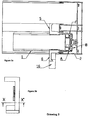
- the vertical profile (10) of the sliding leaf (1) has side A located inside the building, side C located outside the building and side B which is its front side, i.e. the one entering the case (2) of the frame and locking onto the case (2).
- the locking mechanism is located on the vertical side profile (10) of the sliding leaf (1) that is fully inserted into the case (2) of the frame.
- the case (2) may be built-in, i.e. it may be covered by the walls completely, or part of it may remain outside the walls.
- the locking mechanism disassembled, consists of a transmission component (3), a retainer (4) of the transmission component, an outside (5) and an inside (6) handle, a bowden cable (7), and at least two lock strike plates (8), which are fitted on a bowden cable on the vertical profile (10) of the sliding leaf (1), as well as of a respective number of locking hooks (9) with the strike plates (8) located on the frame case (2).
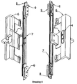
- the side vertical profile (10) of the sliding leaf (1) on side A has a hole (12) for fitting the transmission component (3) and two holes (11a and 11b) both of similar cross-section equally spaced above and below the hole (12), for fitting the inside handle (6).
- Side C of the vertical profile (10) has only two holes (11c and 11d) for fitting the outside handle (5), which have both the same cross section, and are at the same level with the two holes (11 a and 11b) supporting the inside handle (6).
- the vertical side profile (10) on the front side of B that enters the frame case (2) and locks onto the case (2) has:
- the vertical profile (10) also has on the front side of B, a hole (14) corresponding to the hole (12) for fitting the transmission component (3) of side A, on the same horizontal level with the hole (12).
- the vertical profile (10) has a channel (29) formed along its length, for placing the bowden cable (7) and the lock strike plates (8) inside, which are at least two.
- the locking hooks (9) are fitted and fixed without being able to move, at equal numbers with the lock strike plates (8) in points opposite thereto.
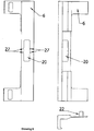
- the handle has two parts: the inside (6) handle located on inner side A of the vertical profile (10) and the outside (5) handle located on outer side C of the vertical profile (10).
- the inside handle (6) fitted on side A of the vertical profile (10) has a hole (20) and a recess (21) for mounting the transmission component (3), which can be rectangular in shape, or tiered, etc.
- Both ends of the inside handle (6) have two identical protrusions (22) so it can be mounted and fixed in holes (11a and 11b) located on side A of the vertical profile (10).
- the protrusions (22) have holes (25) for fixing the inside handle (6), through the corresponding holes (13a and 13b) of the front part B of the vertical profile (10).
- the hole (20) where the restrainer (4) of the transmission component (3) is fitted and fixed has configurations on its walls (27).
- the retainer (4) has configurations (26) on its main part (e.g. springs) corresponding to the configurations (27) of the hole (20) and holes (28).
- the outside handle (5) has the same protrusions (22) with holes (25) for fixing purposes, just like the inside (6) handle.
- the bowden cable (7) has two connection holes (24) with the transmission component (3).
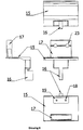
- the transmission component (3) is an element that has a support base (15), a controller (16) and a protrusion (17), either in the form of one single component or in the form of an assembly.
- the base (15) is flat. Its bottom behind the controller (16) has holes (18) in a rectangular recess (19).
- the controller (16) is perpendicular to the base (15).
- the protrusion (17) has two through holes (23) connecting to the bowden cable (7) corresponding to the holes (24) of the bowden cable (7).
- the protrusion (17) located inside the vertical profile (10) serves as an extension for the controller (16) located outside the vertical profile (10) and outside the case (2).
- the locking mechanism is assembled and operated as follows:
- the transmission component (3) is mounted along with its flat base (15) inside the recess (21) of the inside handle (6).
- the retainer (4) is fitted into the rectangular recess (19) of the transmission component base (15) through the main hole (20).
- the two transmission components (3) and retainers (4) are screwed into the holes (28 and 18) they have and now move as one inside the hole (20) giving a linear back and forth motion in the recess (21) of the inside handle (6).
- the controller (16) protrudes from the handle (6) to allow easy access and operation ( Figure 3 ).
- the handle (6) assembled with the transmission component (3) and the retainer (4), is fitted in the vertical profile (10) as follows: the protrusion (17) of the transmission component (3) enters the hole (12) on side A on the side (10), then the similar protrusions (22) of the handle (6) enter the holes (11a and 11b) located in side A of the vertical profile (10).
- the handle (6) is fixed by fastening screws in the corresponding holes (13a and 13b) of part B of the vertical profile (10) with the holes (25) of the handle's (6) protrusions (22).
- the outside handle (5) is fitted on side C of the vertical profile (10) as follows: the identical protrusions (22) of the handle (5) enter the holes (11c and 11d) located on the side C of the vertical profile (10).
- the handle (5) is fixed by fastening screws in the corresponding holes (13c and 13d) of side B of the vertical profile (10) with the holes (25) of the handle's (5) protrusions (22).
- the bowden cable (7) is slided into the channel configuration (29), as well as the lock strike plates (8) that are at least two.
- the transmission component (3) is screwed on the bowden cable (7) in the through holes (23) of the component (3) and in the through holes (24) of the bowden cable (7) and the locking mechanism for the hidden recessed frame is ready to use.
- the mechanism works as follows: To lock the frame, the user pushes the leaf (1) towards the frame case (2) by means of the inside handle (6). As illustrated in drawing 3, the leaf (1) enters the case, and stops at the end of the case (2). The entire vertical profile (10) enters the case (2) and is no longer visible to the user.
- the user pushes the controller (16) of the transmission component (3) down, the base (15) of the transmission component (3) moves inside the recess (21) of the inside handle (6), the configurations (26) of the component's (3) retainer (4) fit into the configurations (27) of the handle's (6) hole (20).
- As the transmission component (3) moves downwards its protrusion (17) moves and drags the bowden cable (7) and the lock strike plates (8) mounted on the bowden cable (7) engage with the locking hooks (9) located on the frame case (2) and the frame locks.
- the present invention can be applied in all door and window openings covered by sliding frames, whether bypass or not.
Landscapes
- Engineering & Computer Science (AREA)
- Civil Engineering (AREA)
- Structural Engineering (AREA)
- Wing Frames And Configurations (AREA)
- Power-Operated Mechanisms For Wings (AREA)
- Mechanical Control Devices (AREA)
Applications Claiming Priority (1)
| Application Number | Priority Date | Filing Date | Title |
|---|---|---|---|
| GR20200100076A GR1010046B (el) | 2020-02-17 | 2020-02-17 | Μηχανισμος κλειδωματος για κρυφο χωνευτο κουφωμα |
Publications (3)
| Publication Number | Publication Date |
|---|---|
| EP3865644A1 true EP3865644A1 (fr) | 2021-08-18 |
| EP3865644B1 EP3865644B1 (fr) | 2024-04-03 |
| EP3865644C0 EP3865644C0 (fr) | 2024-04-03 |
Family
ID=74572724
Family Applications (1)
| Application Number | Title | Priority Date | Filing Date |
|---|---|---|---|
| EP21386004.2A Active EP3865644B1 (fr) | 2020-02-17 | 2021-01-19 | Mécanisme de verrouillage pour cadre encastré caché |
Country Status (2)
| Country | Link |
|---|---|
| EP (1) | EP3865644B1 (fr) |
| GR (1) | GR1010046B (fr) |
Cited By (3)
| Publication number | Priority date | Publication date | Assignee | Title |
|---|---|---|---|---|
| WO2024079545A1 (fr) | 2022-10-10 | 2024-04-18 | Seu Plastics One Man L.L.C. | Lame coulissante à verrou détachable |
| GR20220100831A (el) * | 2022-10-10 | 2024-05-16 | Πλαστικα Νοτιοανατολικης Ευρωπης Μονοπροσωπη Εταιρεια Περιορισμενης Ευθυνης, | Συναρμολογουμενο συρομενο φυλλο με κλειδαρια |
| LU503223B1 (fr) * | 2022-12-20 | 2024-06-20 | Aluk S A | Ouvrant comportant une poignée et huisserie comportant un tel ouvrant |
Citations (8)
| Publication number | Priority date | Publication date | Assignee | Title |
|---|---|---|---|---|
| DE2945507A1 (de) * | 1979-11-10 | 1981-05-21 | DOM-Sicherheitstechnik GmbH & Co KG, 5040 Brühl | Schiebetuerschloss |
| FR2702511A1 (fr) * | 1993-03-09 | 1994-09-16 | Rolleghem Van Claude | Dispositif de serrure pour menuiserie à vantaux coulissants. |
| EP1308588A1 (fr) * | 2001-11-05 | 2003-05-07 | Charles Prunet | Dispositif de verroulilage/déverrouillage multi-pênes pour ouvrant coulissant |
| EP1353034B1 (fr) | 2002-04-10 | 2008-07-30 | Beat GUHL | Construction de cadre pour porte coulissante |
| EP2921624A1 (fr) | 2014-03-18 | 2015-09-23 | YKK AP Inc. | Ferrure |
| EP2853674B1 (fr) | 2013-08-13 | 2016-04-27 | B. Bras & Goncalves-Sistema de Caixilharia, LDA | Cadre pour la fabrication de portes ou de fenêtres de grandes dimensions |
| WO2017195064A1 (fr) | 2016-05-10 | 2017-11-16 | Bbg S.A. | Huisseries pour la fabrication de portes ou de fenêtres à surfaces importantes |
| EP3543449A1 (fr) * | 2018-03-19 | 2019-09-25 | CFT Carbon Fiber Technologies Private Company | Ensemble de porte coulissante à économie d'énergie |
Family Cites Families (3)
| Publication number | Priority date | Publication date | Assignee | Title |
|---|---|---|---|---|
| FR2912175B1 (fr) * | 2007-02-02 | 2009-04-17 | Norsk Hydro As | Chassis de porte ou fenetre a serrure comportant un cadre et au moins un ouvrant coulissant. |
| CH708701A2 (de) * | 2013-10-02 | 2015-04-15 | Berger Metallbau Ag | Schiebewand. |
| GR20140100216A (el) * | 2014-04-16 | 2015-12-09 | Χαραλαμπος Κωνσταντινου Βασιλοπουλος | Μηχανισμος ασφαλισης κουφωματων |
-
2020
- 2020-02-17 GR GR20200100076A patent/GR1010046B/el active IP Right Grant
-
2021
- 2021-01-19 EP EP21386004.2A patent/EP3865644B1/fr active Active
Patent Citations (8)
| Publication number | Priority date | Publication date | Assignee | Title |
|---|---|---|---|---|
| DE2945507A1 (de) * | 1979-11-10 | 1981-05-21 | DOM-Sicherheitstechnik GmbH & Co KG, 5040 Brühl | Schiebetuerschloss |
| FR2702511A1 (fr) * | 1993-03-09 | 1994-09-16 | Rolleghem Van Claude | Dispositif de serrure pour menuiserie à vantaux coulissants. |
| EP1308588A1 (fr) * | 2001-11-05 | 2003-05-07 | Charles Prunet | Dispositif de verroulilage/déverrouillage multi-pênes pour ouvrant coulissant |
| EP1353034B1 (fr) | 2002-04-10 | 2008-07-30 | Beat GUHL | Construction de cadre pour porte coulissante |
| EP2853674B1 (fr) | 2013-08-13 | 2016-04-27 | B. Bras & Goncalves-Sistema de Caixilharia, LDA | Cadre pour la fabrication de portes ou de fenêtres de grandes dimensions |
| EP2921624A1 (fr) | 2014-03-18 | 2015-09-23 | YKK AP Inc. | Ferrure |
| WO2017195064A1 (fr) | 2016-05-10 | 2017-11-16 | Bbg S.A. | Huisseries pour la fabrication de portes ou de fenêtres à surfaces importantes |
| EP3543449A1 (fr) * | 2018-03-19 | 2019-09-25 | CFT Carbon Fiber Technologies Private Company | Ensemble de porte coulissante à économie d'énergie |
Cited By (4)
| Publication number | Priority date | Publication date | Assignee | Title |
|---|---|---|---|---|
| WO2024079545A1 (fr) | 2022-10-10 | 2024-04-18 | Seu Plastics One Man L.L.C. | Lame coulissante à verrou détachable |
| GR20220100831A (el) * | 2022-10-10 | 2024-05-16 | Πλαστικα Νοτιοανατολικης Ευρωπης Μονοπροσωπη Εταιρεια Περιορισμενης Ευθυνης, | Συναρμολογουμενο συρομενο φυλλο με κλειδαρια |
| LU503223B1 (fr) * | 2022-12-20 | 2024-06-20 | Aluk S A | Ouvrant comportant une poignée et huisserie comportant un tel ouvrant |
| WO2024133365A1 (fr) * | 2022-12-20 | 2024-06-27 | Aluk S.A. | Ouvrant coulissant comportant un manchon avec une poignee et huisserie comportant un tel ouvrant |
Also Published As
| Publication number | Publication date |
|---|---|
| GR20200100076A (fr) | 2021-07-09 |
| EP3865644B1 (fr) | 2024-04-03 |
| GR1010046B (el) | 2021-08-13 |
| EP3865644C0 (fr) | 2024-04-03 |
Similar Documents
| Publication | Publication Date | Title |
|---|---|---|
| EP3865644A1 (fr) | Mécanisme de verrouillage pour cadre encastré caché | |
| EP0049694B1 (fr) | Ensemble de profilés métalliques pour la fabrication de cadres pour portes et fenêtres | |
| CA2287221A1 (fr) | Dispositif de fixation de fenetre | |
| CA2234248A1 (fr) | Mecanisme de verrouillage pour portes coulissantes en verre | |
| EP2060713B1 (fr) | Système de sécurité anti-effraction pour cadres de portes et fenêtres | |
| EP3543449B1 (fr) | Ensemble de porte coulissante à économie d'énergie | |
| WO2017204573A1 (fr) | Structure d'installation connective pour fenêtres et portes modulaires | |
| US5784839A (en) | Easy to assemble window | |
| CA2849157C (fr) | Element intermediaire servant a etendre la profondeur d'une fenetre ou porte et fenetre ou porte construite a l'aide de celui-ci | |
| JP3997488B2 (ja) | 建具 | |
| EP1536092B1 (fr) | Renvoi d'angle pour portes et fênetres | |
| EP1122393B1 (fr) | Cadre de battant et/ou dormant pour fenêtres | |
| JP6749833B2 (ja) | 建具 | |
| EP1743996B1 (fr) | Unité d'actionnement pour portes ou fenêtres | |
| EA014997B1 (ru) | Фурнитура для окон и дверей | |
| EP3567203A1 (fr) | Dispositif de protection des ouvertures dans des bâtiments et constructions | |
| EP2362054A1 (fr) | Profilé de dormant ajustable pour portes et fenêtres | |
| KR102026443B1 (ko) | 창호용 잠금핸들의 설치구조 | |
| EP3211169B1 (fr) | Châssis ayant un élément de blocage pour élément transversal | |
| KR102632014B1 (ko) | 창호 거치형 에어컨 설치 조립체 및 이를 포함하는 창호 | |
| JP2004036381A (ja) | ドア又は窓の障子装置 | |
| EP3874104B1 (fr) | Porte ou fenêtre et système de fermeture pour porte ou fenêtre | |
| EP2942464B1 (fr) | Dispositif de suspension pour fenêtre réversible avec élément profilé intégré de châssis | |
| WO2001065039A1 (fr) | Loquet coulissant ameliore pour cadres de portes et fenetres | |
| JPH0620877Y2 (ja) | シヤツター用中柱のラツチ掛け構造 |
Legal Events
| Date | Code | Title | Description |
|---|---|---|---|
| PUAI | Public reference made under article 153(3) epc to a published international application that has entered the european phase |
Free format text: ORIGINAL CODE: 0009012 |
|
| STAA | Information on the status of an ep patent application or granted ep patent |
Free format text: STATUS: REQUEST FOR EXAMINATION WAS MADE |
|
| 17P | Request for examination filed |
Effective date: 20210215 |
|
| AK | Designated contracting states |
Kind code of ref document: A1 Designated state(s): AL AT BE BG CH CY CZ DE DK EE ES FI FR GB GR HR HU IE IS IT LI LT LU LV MC MK MT NL NO PL PT RO RS SE SI SK SM TR |
|
| GRAP | Despatch of communication of intention to grant a patent |
Free format text: ORIGINAL CODE: EPIDOSNIGR1 |
|
| STAA | Information on the status of an ep patent application or granted ep patent |
Free format text: STATUS: GRANT OF PATENT IS INTENDED |
|
| RIC1 | Information provided on ipc code assigned before grant |
Ipc: E05B 79/20 20140101ALN20231208BHEP Ipc: E06B 3/46 20060101ALN20231208BHEP Ipc: E05C 9/02 20060101ALI20231208BHEP Ipc: E05C 1/04 20060101ALI20231208BHEP Ipc: E05B 65/08 20060101AFI20231208BHEP |
|
| INTG | Intention to grant announced |
Effective date: 20240103 |
|
| GRAS | Grant fee paid |
Free format text: ORIGINAL CODE: EPIDOSNIGR3 |
|
| GRAA | (expected) grant |
Free format text: ORIGINAL CODE: 0009210 |
|
| STAA | Information on the status of an ep patent application or granted ep patent |
Free format text: STATUS: THE PATENT HAS BEEN GRANTED |
|
| RAP3 | Party data changed (applicant data changed or rights of an application transferred) |
Owner name: PLASTICS OF SOUTHEAST EUROPE - ONE MAN LIMITED LIABILITY COMPANY - DISTINCTIVE TITLE SEU PLASTICS - ONE MAN L.L.C. |
|
| 111L | Licence recorded |
Designated state(s): AL AT BE BG CH CY CZ DE DK EE ES FI FR GB GR HR HU IE IS IT LT LU LV MC MK MT NL NO PL PT RO RS SE SI SK SM TR Name of requester: ALUMIL ALUMINIUM INDUSTRY S.A., GR Effective date: 20240214 |
|
| 111L | Licence recorded |
Designated state(s): AL AT BE BG CH CY CZ DE DK EE ES FI FR GB GR HR HU IE IS IT LT LU LV MC MK MT NL NO PL PT RO RS SE SI SK SM TR Name of requester: ALUMIL ALUMINIUM INDUSTRY S.A., GR Effective date: 20240214 |
|
| AK | Designated contracting states |
Kind code of ref document: B1 Designated state(s): AL AT BE BG CH CY CZ DE DK EE ES FI FR GB GR HR HU IE IS IT LI LT LU LV MC MK MT NL NO PL PT RO RS SE SI SK SM TR |
|
| REG | Reference to a national code |
Ref country code: CH Ref legal event code: EP |
|
| REG | Reference to a national code |
Ref country code: IE Ref legal event code: FG4D |
|
| REG | Reference to a national code |
Ref country code: DE Ref legal event code: R096 Ref document number: 602021011244 Country of ref document: DE |
|
| U01 | Request for unitary effect filed |
Effective date: 20240405 |
|
| U07 | Unitary effect registered |
Designated state(s): AT BE BG DE DK EE FI FR IT LT LU LV MT NL PT SE SI Effective date: 20240415 |