EP1352805A1 - Lenkrad-Skelett eines Fahrzeug-Lenkrads - Google Patents
Lenkrad-Skelett eines Fahrzeug-Lenkrads Download PDFInfo
- Publication number
- EP1352805A1 EP1352805A1 EP03004699A EP03004699A EP1352805A1 EP 1352805 A1 EP1352805 A1 EP 1352805A1 EP 03004699 A EP03004699 A EP 03004699A EP 03004699 A EP03004699 A EP 03004699A EP 1352805 A1 EP1352805 A1 EP 1352805A1
- Authority
- EP
- European Patent Office
- Prior art keywords
- section
- steering wheel
- leg
- wall thickness
- spoke
- Prior art date
- Legal status (The legal status is an assumption and is not a legal conclusion. Google has not performed a legal analysis and makes no representation as to the accuracy of the status listed.)
- Granted
Links
- 210000002414 leg Anatomy 0.000 description 46
- 230000000875 corresponding effect Effects 0.000 description 7
- 229910052782 aluminium Inorganic materials 0.000 description 5
- XAGFODPZIPBFFR-UHFFFAOYSA-N aluminium Chemical compound [Al] XAGFODPZIPBFFR-UHFFFAOYSA-N 0.000 description 4
- 229910000831 Steel Inorganic materials 0.000 description 3
- 230000002349 favourable effect Effects 0.000 description 3
- 239000010959 steel Substances 0.000 description 3
- 230000008901 benefit Effects 0.000 description 2
- 230000000694 effects Effects 0.000 description 2
- 229910052749 magnesium Inorganic materials 0.000 description 2
- 239000011777 magnesium Substances 0.000 description 2
- 239000000463 material Substances 0.000 description 2
- 238000000034 method Methods 0.000 description 2
- 230000007704 transition Effects 0.000 description 2
- 229910001018 Cast iron Inorganic materials 0.000 description 1
- FYYHWMGAXLPEAU-UHFFFAOYSA-N Magnesium Chemical compound [Mg] FYYHWMGAXLPEAU-UHFFFAOYSA-N 0.000 description 1
- 230000009471 action Effects 0.000 description 1
- AZDRQVAHHNSJOQ-UHFFFAOYSA-N alumane Chemical group [AlH3] AZDRQVAHHNSJOQ-UHFFFAOYSA-N 0.000 description 1
- 238000005452 bending Methods 0.000 description 1
- 230000015572 biosynthetic process Effects 0.000 description 1
- 238000005266 casting Methods 0.000 description 1
- 230000008859 change Effects 0.000 description 1
- 239000002131 composite material Substances 0.000 description 1
- 238000010276 construction Methods 0.000 description 1
- 229910001234 light alloy Inorganic materials 0.000 description 1
- 229910052751 metal Inorganic materials 0.000 description 1
- 239000002184 metal Substances 0.000 description 1
- 239000011343 solid material Substances 0.000 description 1
- 210000002784 stomach Anatomy 0.000 description 1
- 230000001960 triggered effect Effects 0.000 description 1
- 210000000689 upper leg Anatomy 0.000 description 1
- 230000003313 weakening effect Effects 0.000 description 1
Images


Classifications
-
- B—PERFORMING OPERATIONS; TRANSPORTING
- B62—LAND VEHICLES FOR TRAVELLING OTHERWISE THAN ON RAILS
- B62D—MOTOR VEHICLES; TRAILERS
- B62D1/00—Steering controls, i.e. means for initiating a change of direction of the vehicle
- B62D1/02—Steering controls, i.e. means for initiating a change of direction of the vehicle vehicle-mounted
- B62D1/04—Hand wheels
- B62D1/11—Hand wheels incorporating energy-absorbing arrangements, e.g. by being yieldable or collapsible
Definitions
- the invention relates to a steering wheel skeleton of a vehicle steering wheel with a Hub, at least one outgoing spoke and a steering wheel rim, and in particular a steering wheel skeleton in which the spoke (s) and / or the wreath by side legs and a base leg formed, has a substantially U-shaped cross section.
- the technical environment is only referred to as an example DE 196 32 317 C1 referenced.
- a skeleton of a steering wheel, on which there is then a suitable casing is currently being applied primarily in the case of a Vehicle crashes have a favorable deformation behavior to a Critically high force impact on the driver or vehicle occupant due to an accident to avoid.
- the steering wheel skeleton is mostly specifically designed to be soft or easily deformable.
- Occupant protection values is a particularly good deformation behavior in the Driver's chest or stomach impact area desired.
- the solution to this problem is generally characterized in that about the length of the spoke or the circumference of the wreath considered areas are provided, which are characterized by relatively high rigidity and that at least one section is provided adjacent to these areas, which is more easily deformable compared to the areas with high rigidity.
- substantially U-shaped Cross-section possesses is the solution to the stated problem characterized in that over the length of the spoke or the At least one of the legs considers the circumference of the ring at least a section with one over another section at least partially reduced wall thickness.
- the quasi a special function is assigned to each.
- that Profile or the cross section of the respective section of its associated Function should be designed accordingly, but it is also fundamental conceivable, different materials in the individual sections of a Spoke or the wreath.
- the special functions of the concerns so with or in a first set a relatively high degree of rigidity is generated by sections or areas, which results in a relatively high natural frequency and therefore good vibration comfort of the steering wheel results.
- Areas or sections of the steering wheel rim and / or at least a spoke should clearly have a relatively high deformability are present, i.e. targeted in this or this other area (s) or Section (s) becomes a targeted local for a crash case Compliance achieved.
- a relatively good deformability can be achieved by a wide variety of different methods Measures can be guaranteed, for example by varying the wall thickness (es), by introducing or providing target kink points or target breaking points or target buckling points, or by a targeted change in the respective individual bending resistance torque compared to the neighboring, characterized by a relatively high rigidity Section or area of the spoke or the steering wheel. All of these so far Proposed measures can be done on the otherwise usual Steering wheel skeletons are implemented, for example, in full casting (for example Magnesium or aluminum) skeletons with or without insert (for example made of steel or aluminum), especially in the wreath area Coordination of the moment of inertia.
- the lateral legs be deformed Sections or areas opposite to those adjacent to it Sections or areas may be weakened, but it can also be the so-called base legs lying between the lateral legs in particular in one or that cross-section in which the or the lateral Leg has an at least partially reduced wall thickness or have, also one with respect to an adjacent cross section or Section have at least partially reduced wall thickness.
- the said can partially reduced wall thickness of a section in the form of a recess or of a breakthrough.
- the recess is located at the free end of a leg, so that this leg is shorter than the leg in said section of an adjacent section.
- the mentioned recess also act as a predetermined breaking point and be suitably designed for this, so For example in the form of a notch or the like.
- This crack stop guides the formation of cracks in the event of a desired deformation the intended section of the steering wheel skeleton defined by the notch or predetermined breaking point towards the mentioned breakthrough, so that it is guaranteed that the desired deformation is actually as desired takes place when the steering wheel or the steering wheel skeleton in the case of a vehicle crash is loaded accordingly by the driver or hits the driver accordingly.
- leg (s) in one Section with partially reduced wall thickness compared to the neighboring ones Sections are curved outwards or inwards, so there is already one certain bulge direction specified, in the corresponding The introduction of force can deform the section intended for deformation.
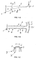
- reference number 1 denotes the hub of a vehicle steering wheel or skeleton of the same, to which a spoke 2 is connected, which — as is generally customary — carries a steering wheel rim 3.
- the rim 3 and / or at least one spoke 2 of which consists of a profile which is essentially U-shaped in cross section, as shown in the other figures (FIGS. 1B, 1C, Fig.2B, Fig.3B and others) emerges.
- This cross-section which is essentially U-shaped, is formed by two lateral legs 4, 5 and a so-called base leg 6 lying between them or connecting them to one another.
- the section 11 with the partially reduced wall thickness is characterized in that a cutout 21 is located in the legs 4, 5 in the region of this section 11 at its free ends, ie the legs 4, 5 in the The area of this section 11 is shorter than the legs 4, 5 of the two sections 12 directly adjacent to the section 11.
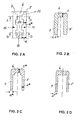
- sections 11 are alternately arranged one behind the other with (compared to the legs 4, 5 in sections 12) reduced wall thickness d * of the legs 4, 5 and sections 12 with (compared to the legs 4, 5 in sections 11) greater wall thickness d of the legs 4, 5 is provided, as can be seen in particular from FIGS . 2A, 2B, 2C . 2C shows that the so-called
- the wall thickness s of the base leg 6 in section 11 is the same as that in section 12.
- FIGS. 2A-2D show the steering wheel skeleton according to the exemplary embodiment according to the sequence of figures 2 in the state not loaded by an extreme force
- FIGS. 2E-2G show the conditions under extreme loads with a force F 1 or F 2 , in an exaggerated representation.
- the legs 4, 5 which are reduced in their wall thickness d * compared to the sections 12, are turned outwards - ie from the line of symmetry of the cross section U -shaped profile away - bulged, as shown in Fig.2F .
- an opposing load which is shown in FIG . 2G , at least some of the sections 11 weakened with respect to the sections 12 will tear or tear open, these cracks being identified by the reference number 22.
- FIG. 2F can namely represent a further embodiment of the present invention even in the unloaded state.
- the legs 4, 5 in section 11 with at least partially reduced wall thickness d * compared to the adjacent sections 12 (with the greater wall thickness d there) are arched outwards - ie away from one another - from the beginning, ie even before a deformation has occurred.
- FIGS. 3A, 3B Another embodiment of the present invention is shown in the sequence of figures 3 .
- the so-called partially reduced wall thickness of a leg 4 or 5 - similar to the sequence of figures 1 - is designed in the form of a recess 21 located at the free end of each leg, which here has the shape of a triangle tapering towards the base leg 6.
- This recess 21 acts as a predetermined breaking point in section 11, so that a (then desired) crack 22 starts from this recess 21 when there is a corresponding load from an unusually high force F, as shown in FIG . 3D .
- FIG. 3D further shows the effect of an opening 23 provided in each leg 4 or 5 between the cutout 21 and the base leg 6 and acting as a so-called crack stopper.
- a crack originating from the cutout 21 under the corresponding action of a force F. 22 will usually only take the shortest route up to this breakthrough 23 and will first be stopped or stopped there.
- Such openings 23 acting as crack stoppers the deformation of the steering wheel or steering wheel skeleton (triggered by an impact) can thus be controlled as desired.
- the existing one conflict of goals between the contrary requirements on the one hand a relative to have a stiff steering wheel - especially with light alloy skeletons high moments of inertia - the natural frequency targets and thus one to achieve good vibration comfort in the vehicle, and on the other hand a relatively well deformable steering wheel to have the load values for the Vehicle occupants or drivers as little as possible in the event of a vehicle crash hold, be resolved, although it should be noted that a variety of details, particularly of a constructive nature, deviate from the Embodiments shown can be designed without the content of Leave claims.
Landscapes
- Engineering & Computer Science (AREA)
- Chemical & Material Sciences (AREA)
- Combustion & Propulsion (AREA)
- Transportation (AREA)
- Mechanical Engineering (AREA)
- Steering Controls (AREA)
- Body Structure For Vehicles (AREA)
Abstract
Description
- Figur 1A
- einen Halbschnitt durch ein erstes Ausführungsbeispiel eines erfindungsgemäßen Lenkrad-Skeletts
- Figur 1B
- die Ansicht U aus Fig.1a
- Figur 1C
- den Schnitt A-A aus Fig.1A im nicht deformierten sowie im deformierten Zustand
- Figur 2A
- die Ansicht von unten (ähnlich Fig.1B) auf das im Querschnitt U-förmige Profil einer Speiche oder des Kranzes eines zweiten Ausführungsbeispiels
- Figur 2B
- den Schnitt A-A aus Fig.2A
- Figur 2C
- den Schnitt B-B aus Fig.2A in einer ersten Ausführungsform
- Figur 2D
- den Schnitt B-B aus Fig.2A in einer zweiten Ausführungsform
- Figur 2E
- die Ansicht auf einen Teil einer Speiche (oder eines Kranzes) mit einem Profil-Querschnitt entsprechend Fig.2A, der durch eine eine Deformation auslösende Kraft F1 belastet wird
- Figur 2F
- eine der Figur 2A entsprechende Ansicht der gemäß Fig.2E belasteten Speiche (oder des Lenkrad-Kranzes)
- Figur 2G
- einen Längsschnitt (entsprechend dem Schnitt A-A aus Fig.2F) durch das Skelett einer Speiche (oder eines Kranzes) mit einem Profil-Querschnitt entsprechend Fig.2A, die oder der durch eine eine Deformation auslösende Kraft F2 belastet wird
- Figur 3A
- eine Seitenansicht einer Speiche (ähnlich der Ansicht in Fig.1A) in einer dritten Ausführungsform der vorliegenden Erfindung
- Figur 3B
- den Schnitt A-A aus Fig.3A
- Figur 3C
- eine Ausführungsvariante zur Gestaltung nach Fig.3A
- Figur 3D
- die Ausführungsform nach Fig.3C im Falle einer eine Deformation auslösenden Belastung durch eine Kraft F
Claims (9)
- Lenkrad-Skelett eines Fahrzeug-Lenkrads mit einer Nabe (1), zumindest einer davon abgehenden Speiche (2) sowie einem Lenkrad-Kranz (3),
dadurch gekennzeichnet, dass über der Länge der Speiche (2) oder dem Umfang des Kranzes (3) betrachtet Bereiche (12) vorgesehen sind, die sich durch relativ hohe Steifigkeit auszeichnen und dass diesen Bereichen (12) benachbart zumindest ein Abschnitt (11) vorgesehen ist, der gegenüber den Bereichen (12) mit hoher Steifigkeit leichter deformierbar ist. - Lenkrad-Skelett nach Anspruch 1, wobei die Speiche(n) (2) und/oder der Kranz (3) einen durch seitliche Schenkel (4, 5) sowie einen Basis-Schenkel (6) gebildeten, im wesentlichen U-förmigen Querschnitt besitzt/besitzen,
dadurch gekennzeichnet, dass über der Länge der Speiche (2) oder dem Umfang des Kranzes (3) betrachtet zumindest einer der Schenkel (4, 5) zumindest einen Abschnitt (11) mit einer gegenüber einem anderen Abschnitt (12) zumindest teilweise verringerten Wandstärke aufweist. - Lenkrad-Skelett nach Anspruch 2,
dadurch gekennzeichnet, dass die beiden einander gegenüberliegenden Schenkel (4, 5) jeweils einander gegenüberliegende Abschnitte (11) mit jeweils einer gegenüber benachbarten Abschnitten (12) zumindest teilweise verringerten Wandstärke aufweisen. - Lenkrad-Skelett nach Anspruch 2 oder 3,
dadurch gekennzeichnet, dass der Basis-Schenkel (6) in einem Querschnitt, in dem der oder die seitlichen Schenkel (4, 5) eine zumindest teilweise verringerte Wandstärke (d*) aufweist oder aufweisen, ebenfalls eine gegenüber einem benachbarten Querschnitt oder Abschnitt (12) zumindest teilweise verringerte Wandstärke (s*) aufweist. - Lenkrad-Skelett nach einem der vorangegangenen Ansprüche,
dadurch gekennzeichnet, dass die teilweise verringerte Wandstärke eines Abschnitts (11) in Form einer Aussparung (21) oder eines Durchbruchs (23) ausgebildet ist. - Lenkrad-Skelett nach Anspruch 5,
dadurch gekennzeichnet, dass sich die Aussparung (21) am freien Ende eines Schenkels (4, 5) befindet, so dass dieser Schenkel (4, 5) im besagten Abschnitt (11) kürzer ist als der Schenkel (4, 5) eines benachbarten Abschnitts (12). - Lenkrad-Skelett nach Anspruch 5,
dadurch gekennzeichnet, dass sich die Aussparung (21) am freien Ende eines Schenkels (4, 5) befindet und als Sollbruchstelle fungiert, und dass im Schenkel (4, 5) zwischen dieser Aussparung (21) und dem Basis-Schenkel (6) ein Riss-Stopper in Form eines Durchbruchs (23) oder dgl. vorgesehen ist. - Lenkrad-Skelett nach einem der vorangegangenen Ansprüche,
dadurch gekennzeichnet, dass bei einer Speiche (2) der oder die Abschnitt(e) (11) mit zumindest teilweise verringerter Wandstärke näher an der Nabe (1) als am Kranz (3) vorgesehen sind. - Lenkrad-Skelett nach einem der vorangegangenen Ansprüche,
dadurch gekennzeichnet, dass der oder die Schenkel (4, 5) in einem Abschnitt (11) mit zumindest teilweise verringerter Wandstärke gegenüber den benachbarten Abschnitten (12) nach außen oder innen gewölbt sind.
Applications Claiming Priority (2)
| Application Number | Priority Date | Filing Date | Title |
|---|---|---|---|
| DE10215684 | 2002-04-10 | ||
| DE2002115684 DE10215684A1 (de) | 2002-04-10 | 2002-04-10 | Lenkrad-Skelett eines Fahrzeug-Lenkrads |
Publications (2)
| Publication Number | Publication Date |
|---|---|
| EP1352805A1 true EP1352805A1 (de) | 2003-10-15 |
| EP1352805B1 EP1352805B1 (de) | 2006-06-07 |
Family
ID=28051233
Family Applications (1)
| Application Number | Title | Priority Date | Filing Date |
|---|---|---|---|
| EP20030004699 Expired - Lifetime EP1352805B1 (de) | 2002-04-10 | 2003-03-04 | Lenkrad-Skelett eines Fahrzeug-Lenkrads |
Country Status (3)
| Country | Link |
|---|---|
| EP (1) | EP1352805B1 (de) |
| DE (2) | DE10215684A1 (de) |
| ES (1) | ES2265070T3 (de) |
Citations (7)
| Publication number | Priority date | Publication date | Assignee | Title |
|---|---|---|---|---|
| DE1159287B (de) * | 1962-01-16 | 1963-12-12 | Leopold F Schmid | Lenkrad fuer Kraftfahrzeuge mit einer tief liegenden Nabe |
| JPH07257394A (ja) * | 1994-03-28 | 1995-10-09 | Nippon Plast Co Ltd | ステアリングホイール |
| JPH07323845A (ja) * | 1994-05-31 | 1995-12-12 | Tokyo Seat Kk | ステアリングホイール |
| JPH08104239A (ja) * | 1994-09-30 | 1996-04-23 | Suzuki Motor Corp | ステアリングホイールの取付構造 |
| JPH08133093A (ja) * | 1994-11-08 | 1996-05-28 | Toyoda Gosei Co Ltd | ステアリングホイール |
| DE19632317C1 (de) | 1996-08-10 | 1998-01-29 | Mst Automotive Gmbh | Lenkradskelett für Kraftfahrzeuge |
| JP2000296778A (ja) * | 1999-02-10 | 2000-10-24 | Toyota Motor Corp | ステアリングホイール構造 |
Family Cites Families (6)
| Publication number | Priority date | Publication date | Assignee | Title |
|---|---|---|---|---|
| DE2351497C2 (de) * | 1973-10-13 | 1975-11-20 | Audi Nsu Auto Union Ag, 7107 Neckarsulm | Kraftfahrzeuglenkrad |
| JPS62178469A (ja) * | 1986-01-31 | 1987-08-05 | Toyoda Gosei Co Ltd | ステアリングホイ−ル心金 |
| US5243877A (en) * | 1992-03-30 | 1993-09-14 | Ryusaku Numata | Steering wheel rim |
| DE9207561U1 (de) * | 1992-06-04 | 1992-09-10 | R.d.i. Italia S.r.l., Mirabello-Ferrara | Lenkrad für Kraftfahrzeuge |
| US5490435A (en) * | 1994-08-25 | 1996-02-13 | Chrysler Corporation | Energy absorbing steering wheel |
| DE29820305U1 (de) * | 1998-11-12 | 1999-01-14 | TRW Automotive Safety Systems GmbH, 63743 Aschaffenburg | Lenkrad mit metallischem Skelett |
-
2002
- 2002-04-10 DE DE2002115684 patent/DE10215684A1/de not_active Withdrawn
-
2003
- 2003-03-04 EP EP20030004699 patent/EP1352805B1/de not_active Expired - Lifetime
- 2003-03-04 DE DE50303638T patent/DE50303638D1/de not_active Expired - Lifetime
- 2003-03-04 ES ES03004699T patent/ES2265070T3/es not_active Expired - Lifetime
Patent Citations (8)
| Publication number | Priority date | Publication date | Assignee | Title |
|---|---|---|---|---|
| DE1159287B (de) * | 1962-01-16 | 1963-12-12 | Leopold F Schmid | Lenkrad fuer Kraftfahrzeuge mit einer tief liegenden Nabe |
| JPH07257394A (ja) * | 1994-03-28 | 1995-10-09 | Nippon Plast Co Ltd | ステアリングホイール |
| JPH07323845A (ja) * | 1994-05-31 | 1995-12-12 | Tokyo Seat Kk | ステアリングホイール |
| JPH08104239A (ja) * | 1994-09-30 | 1996-04-23 | Suzuki Motor Corp | ステアリングホイールの取付構造 |
| JPH08133093A (ja) * | 1994-11-08 | 1996-05-28 | Toyoda Gosei Co Ltd | ステアリングホイール |
| DE19632317C1 (de) | 1996-08-10 | 1998-01-29 | Mst Automotive Gmbh | Lenkradskelett für Kraftfahrzeuge |
| EP0825090A2 (de) * | 1996-08-10 | 1998-02-25 | MST Automotive GmbH Automobil-Sicherheitstechnik | Lenkradskelett für Kraftfahrzeuge |
| JP2000296778A (ja) * | 1999-02-10 | 2000-10-24 | Toyota Motor Corp | ステアリングホイール構造 |
Non-Patent Citations (5)
| Title |
|---|
| PATENT ABSTRACTS OF JAPAN vol. 1996, no. 02 29 February 1996 (1996-02-29) * |
| PATENT ABSTRACTS OF JAPAN vol. 1996, no. 04 30 April 1996 (1996-04-30) * |
| PATENT ABSTRACTS OF JAPAN vol. 1996, no. 08 30 August 1996 (1996-08-30) * |
| PATENT ABSTRACTS OF JAPAN vol. 1996, no. 09 30 September 1996 (1996-09-30) * |
| PATENT ABSTRACTS OF JAPAN vol. 2000, no. 13 5 February 2001 (2001-02-05) * |
Also Published As
| Publication number | Publication date |
|---|---|
| DE10215684A1 (de) | 2003-10-30 |
| DE50303638D1 (de) | 2006-07-20 |
| EP1352805B1 (de) | 2006-06-07 |
| ES2265070T3 (es) | 2007-02-01 |
Similar Documents
| Publication | Publication Date | Title |
|---|---|---|
| DE4241879C2 (de) | Radführungslenker für Kraftfahrzeuge | |
| DE60303102T2 (de) | Scheinwerfer mit Energieabsorptionsmitteln | |
| DE112010006033T5 (de) | Fahrzeugstossfängerträger und Verfahren zur Herstellung desselben | |
| EP0479401B1 (de) | Aufprallträger | |
| DE19818590A1 (de) | Ölwanne | |
| DE102007018715A1 (de) | Fahrzeugsitz | |
| EP1503932B1 (de) | Anbindung für ein fahrerhaus | |
| DE3127172A1 (de) | Armaturenbrett fuer ein kraftfahrzeug | |
| DE19858303B4 (de) | Vorbaustruktur für eine selbsttragende Rohbaukarosserie eines Personenkraftwagens | |
| DE4307994A1 (de) | Verbindung einer Welle bzw. Bolzen mit einem Kurbelhebel einer Wischanlage | |
| DE2325692A1 (de) | Fahrzeugrahmen | |
| DE4419378A1 (de) | Formteilanordnung am Radausschnitt eines Personenkraftwagens | |
| DE102013003433A1 (de) | Haube für ein Kraftfahrzeug | |
| EP0467829B1 (de) | Als Hohlprofil ausgebildeter Aufprallträger für Fahrzeugtüren | |
| DE29802474U1 (de) | Lenkrad für Kraftfahrzeuge | |
| DE102014115938B4 (de) | Strukturträger für ein Kraftfahrzeug | |
| EP1352805A1 (de) | Lenkrad-Skelett eines Fahrzeug-Lenkrads | |
| DE60000230T2 (de) | Hydraulischer Druckerzeuger für Fahrzeuge | |
| DE10214862C5 (de) | Hardtop für ein Cabriolet-Fahrzeug | |
| DE2012033B2 (de) | Auffahrschutzvorrichtung an der rueckseite von fahrzeugen | |
| DE102004053020A1 (de) | Karosserieteil für ein Kraftfahrzeug | |
| DE10360124A1 (de) | Knieaufprallelement für Kraftfahrzeuge | |
| DE102005028770A1 (de) | Kraftfahrzeug | |
| DE102009051039B4 (de) | Gussteil für eine Karosserie eines Kraftfahrzeugs | |
| DE10314021A1 (de) | Stoßfänger mit Einrollsicke |
Legal Events
| Date | Code | Title | Description |
|---|---|---|---|
| PUAI | Public reference made under article 153(3) epc to a published international application that has entered the european phase |
Free format text: ORIGINAL CODE: 0009012 |
|
| AK | Designated contracting states |
Kind code of ref document: A1 Designated state(s): AT BE BG CH CY CZ DE DK EE ES FI FR GB GR HU IE IT LI LU MC NL PT RO SE SI SK TR |
|
| AX | Request for extension of the european patent |
Extension state: AL LT LV MK |
|
| 17P | Request for examination filed |
Effective date: 20031218 |
|
| AKX | Designation fees paid |
Designated state(s): DE ES FR GB IT |
|
| GRAP | Despatch of communication of intention to grant a patent |
Free format text: ORIGINAL CODE: EPIDOSNIGR1 |
|
| GRAS | Grant fee paid |
Free format text: ORIGINAL CODE: EPIDOSNIGR3 |
|
| GRAA | (expected) grant |
Free format text: ORIGINAL CODE: 0009210 |
|
| AK | Designated contracting states |
Kind code of ref document: B1 Designated state(s): DE ES FR GB IT |
|
| PG25 | Lapsed in a contracting state [announced via postgrant information from national office to epo] |
Ref country code: IT Free format text: LAPSE BECAUSE OF FAILURE TO SUBMIT A TRANSLATION OF THE DESCRIPTION OR TO PAY THE FEE WITHIN THE PRESCRIBED TIME-LIMIT;WARNING: LAPSES OF ITALIAN PATENTS WITH EFFECTIVE DATE BEFORE 2007 MAY HAVE OCCURRED AT ANY TIME BEFORE 2007. THE CORRECT EFFECTIVE DATE MAY BE DIFFERENT FROM THE ONE RECORDED. Effective date: 20060607 |
|
| REG | Reference to a national code |
Ref country code: GB Ref legal event code: FG4D Free format text: NOT ENGLISH |
|
| REF | Corresponds to: |
Ref document number: 50303638 Country of ref document: DE Date of ref document: 20060720 Kind code of ref document: P |
|
| GBT | Gb: translation of ep patent filed (gb section 77(6)(a)/1977) |
Effective date: 20060705 |
|
| ET | Fr: translation filed | ||
| REG | Reference to a national code |
Ref country code: ES Ref legal event code: FG2A Ref document number: 2265070 Country of ref document: ES Kind code of ref document: T3 |
|
| PLBE | No opposition filed within time limit |
Free format text: ORIGINAL CODE: 0009261 |
|
| STAA | Information on the status of an ep patent application or granted ep patent |
Free format text: STATUS: NO OPPOSITION FILED WITHIN TIME LIMIT |
|
| 26N | No opposition filed |
Effective date: 20070308 |
|
| REG | Reference to a national code |
Ref country code: FR Ref legal event code: PLFP Year of fee payment: 13 |
|
| PGFP | Annual fee paid to national office [announced via postgrant information from national office to epo] |
Ref country code: ES Payment date: 20150220 Year of fee payment: 13 Ref country code: IT Payment date: 20150328 Year of fee payment: 13 Ref country code: DE Payment date: 20150314 Year of fee payment: 13 |
|
| PGFP | Annual fee paid to national office [announced via postgrant information from national office to epo] |
Ref country code: GB Payment date: 20150326 Year of fee payment: 13 |
|
| PGFP | Annual fee paid to national office [announced via postgrant information from national office to epo] |
Ref country code: FR Payment date: 20150330 Year of fee payment: 13 |
|
| REG | Reference to a national code |
Ref country code: DE Ref legal event code: R119 Ref document number: 50303638 Country of ref document: DE |
|
| GBPC | Gb: european patent ceased through non-payment of renewal fee |
Effective date: 20160304 |
|
| REG | Reference to a national code |
Ref country code: FR Ref legal event code: ST Effective date: 20161130 |
|
| PG25 | Lapsed in a contracting state [announced via postgrant information from national office to epo] |
Ref country code: DE Free format text: LAPSE BECAUSE OF NON-PAYMENT OF DUE FEES Effective date: 20161001 Ref country code: FR Free format text: LAPSE BECAUSE OF NON-PAYMENT OF DUE FEES Effective date: 20160331 Ref country code: GB Free format text: LAPSE BECAUSE OF NON-PAYMENT OF DUE FEES Effective date: 20160304 |
|
| PG25 | Lapsed in a contracting state [announced via postgrant information from national office to epo] |
Ref country code: IT Free format text: LAPSE BECAUSE OF NON-PAYMENT OF DUE FEES Effective date: 20160304 |
|
| REG | Reference to a national code |
Ref country code: ES Ref legal event code: FD2A Effective date: 20170428 |
|
| PG25 | Lapsed in a contracting state [announced via postgrant information from national office to epo] |
Ref country code: ES Free format text: LAPSE BECAUSE OF NON-PAYMENT OF DUE FEES Effective date: 20160305 |