EP1348643A1 - Behältnis und Palette zur Aufnahme von Schaufeln einer Strömungsmaschine - Google Patents
Behältnis und Palette zur Aufnahme von Schaufeln einer Strömungsmaschine Download PDFInfo
- Publication number
- EP1348643A1 EP1348643A1 EP03006630A EP03006630A EP1348643A1 EP 1348643 A1 EP1348643 A1 EP 1348643A1 EP 03006630 A EP03006630 A EP 03006630A EP 03006630 A EP03006630 A EP 03006630A EP 1348643 A1 EP1348643 A1 EP 1348643A1
- Authority
- EP
- European Patent Office
- Prior art keywords
- pallet
- pyramid
- container
- blades
- blade
- Prior art date
- Legal status (The legal status is an assumption and is not a legal conclusion. Google has not performed a legal analysis and makes no representation as to the accuracy of the status listed.)
- Granted
Links
- 229920003023 plastic Polymers 0.000 claims description 22
- 239000004033 plastic Substances 0.000 claims description 22
- 238000007789 sealing Methods 0.000 claims description 21
- -1 polyethylene Polymers 0.000 claims description 10
- 238000002347 injection Methods 0.000 claims description 9
- 239000007924 injection Substances 0.000 claims description 9
- 238000007667 floating Methods 0.000 claims description 6
- 239000004698 Polyethylene Substances 0.000 claims description 5
- 239000004642 Polyimide Substances 0.000 claims description 5
- 239000004743 Polypropylene Substances 0.000 claims description 5
- 239000004793 Polystyrene Substances 0.000 claims description 5
- 239000000203 mixture Substances 0.000 claims description 5
- 229920000573 polyethylene Polymers 0.000 claims description 5
- 229920001721 polyimide Polymers 0.000 claims description 5
- 229920000642 polymer Polymers 0.000 claims description 5
- 229920001155 polypropylene Polymers 0.000 claims description 5
- 229920002223 polystyrene Polymers 0.000 claims description 5
- 229920000915 polyvinyl chloride Polymers 0.000 claims description 5
- 239000004800 polyvinyl chloride Substances 0.000 claims description 5
- 230000008901 benefit Effects 0.000 description 19
- 239000012530 fluid Substances 0.000 description 5
- 239000011261 inert gas Substances 0.000 description 5
- 238000003860 storage Methods 0.000 description 5
- 238000013459 approach Methods 0.000 description 4
- 238000011109 contamination Methods 0.000 description 4
- 239000002184 metal Substances 0.000 description 4
- 229910052751 metal Inorganic materials 0.000 description 4
- 238000000034 method Methods 0.000 description 4
- 229920000426 Microplastic Polymers 0.000 description 3
- 239000000919 ceramic Substances 0.000 description 3
- 238000005516 engineering process Methods 0.000 description 3
- 239000000835 fiber Substances 0.000 description 3
- 238000001746 injection moulding Methods 0.000 description 3
- 230000008569 process Effects 0.000 description 3
- 238000009833 condensation Methods 0.000 description 2
- 230000005494 condensation Effects 0.000 description 2
- 238000013461 design Methods 0.000 description 2
- 238000011161 development Methods 0.000 description 2
- 230000018109 developmental process Effects 0.000 description 2
- 239000007789 gas Substances 0.000 description 2
- 239000008187 granular material Substances 0.000 description 2
- 239000007788 liquid Substances 0.000 description 2
- 238000004519 manufacturing process Methods 0.000 description 2
- 239000000463 material Substances 0.000 description 2
- 239000007858 starting material Substances 0.000 description 2
- XLYOFNOQVPJJNP-UHFFFAOYSA-N water Substances O XLYOFNOQVPJJNP-UHFFFAOYSA-N 0.000 description 2
- FGRBYDKOBBBPOI-UHFFFAOYSA-N 10,10-dioxo-2-[4-(N-phenylanilino)phenyl]thioxanthen-9-one Chemical compound O=C1c2ccccc2S(=O)(=O)c2ccc(cc12)-c1ccc(cc1)N(c1ccccc1)c1ccccc1 FGRBYDKOBBBPOI-UHFFFAOYSA-N 0.000 description 1
- 241000191291 Abies alba Species 0.000 description 1
- 241000196324 Embryophyta Species 0.000 description 1
- 230000006978 adaptation Effects 0.000 description 1
- 238000004140 cleaning Methods 0.000 description 1
- 239000000356 contaminant Substances 0.000 description 1
- 239000000112 cooling gas Substances 0.000 description 1
- 230000001419 dependent effect Effects 0.000 description 1
- 230000003467 diminishing effect Effects 0.000 description 1
- 239000000945 filler Substances 0.000 description 1
- 239000003365 glass fiber Substances 0.000 description 1
- 239000002241 glass-ceramic Substances 0.000 description 1
- 238000000227 grinding Methods 0.000 description 1
- 238000010438 heat treatment Methods 0.000 description 1
- 230000006872 improvement Effects 0.000 description 1
- 238000007373 indentation Methods 0.000 description 1
- 238000003780 insertion Methods 0.000 description 1
- 230000037431 insertion Effects 0.000 description 1
- 150000002739 metals Chemical class 0.000 description 1
- 239000002245 particle Substances 0.000 description 1
- 238000010926 purge Methods 0.000 description 1
- 238000003892 spreading Methods 0.000 description 1
- 230000007480 spreading Effects 0.000 description 1
- 238000003856 thermoforming Methods 0.000 description 1
Images



Classifications
-
- F—MECHANICAL ENGINEERING; LIGHTING; HEATING; WEAPONS; BLASTING
- F01—MACHINES OR ENGINES IN GENERAL; ENGINE PLANTS IN GENERAL; STEAM ENGINES
- F01D—NON-POSITIVE DISPLACEMENT MACHINES OR ENGINES, e.g. STEAM TURBINES
- F01D25/00—Component parts, details, or accessories, not provided for in, or of interest apart from, other groups
-
- B—PERFORMING OPERATIONS; TRANSPORTING
- B65—CONVEYING; PACKING; STORING; HANDLING THIN OR FILAMENTARY MATERIAL
- B65D—CONTAINERS FOR STORAGE OR TRANSPORT OF ARTICLES OR MATERIALS, e.g. BAGS, BARRELS, BOTTLES, BOXES, CANS, CARTONS, CRATES, DRUMS, JARS, TANKS, HOPPERS, FORWARDING CONTAINERS; ACCESSORIES, CLOSURES, OR FITTINGS THEREFOR; PACKAGING ELEMENTS; PACKAGES
- B65D25/00—Details of other kinds or types of rigid or semi-rigid containers
- B65D25/02—Internal fittings
- B65D25/10—Devices to locate articles in containers
-
- B—PERFORMING OPERATIONS; TRANSPORTING
- B65—CONVEYING; PACKING; STORING; HANDLING THIN OR FILAMENTARY MATERIAL
- B65D—CONTAINERS FOR STORAGE OR TRANSPORT OF ARTICLES OR MATERIALS, e.g. BAGS, BARRELS, BOTTLES, BOXES, CANS, CARTONS, CRATES, DRUMS, JARS, TANKS, HOPPERS, FORWARDING CONTAINERS; ACCESSORIES, CLOSURES, OR FITTINGS THEREFOR; PACKAGING ELEMENTS; PACKAGES
- B65D71/00—Bundles of articles held together by packaging elements for convenience of storage or transport, e.g. portable segregating carrier for plural receptacles such as beer cans or pop bottles; Bales of material
- B65D71/70—Trays provided with projections or recesses in order to assemble multiple articles, e.g. intermediate elements for stacking
-
- F—MECHANICAL ENGINEERING; LIGHTING; HEATING; WEAPONS; BLASTING
- F01—MACHINES OR ENGINES IN GENERAL; ENGINE PLANTS IN GENERAL; STEAM ENGINES
- F01D—NON-POSITIVE DISPLACEMENT MACHINES OR ENGINES, e.g. STEAM TURBINES
- F01D5/00—Blades; Blade-carrying members; Heating, heat-insulating, cooling or antivibration means on the blades or the members
-
- B—PERFORMING OPERATIONS; TRANSPORTING
- B65—CONVEYING; PACKING; STORING; HANDLING THIN OR FILAMENTARY MATERIAL
- B65D—CONTAINERS FOR STORAGE OR TRANSPORT OF ARTICLES OR MATERIALS, e.g. BAGS, BARRELS, BOTTLES, BOXES, CANS, CARTONS, CRATES, DRUMS, JARS, TANKS, HOPPERS, FORWARDING CONTAINERS; ACCESSORIES, CLOSURES, OR FITTINGS THEREFOR; PACKAGING ELEMENTS; PACKAGES
- B65D2585/00—Containers, packaging elements or packages specially adapted for particular articles or materials
- B65D2585/68—Containers, packaging elements or packages specially adapted for particular articles or materials for machines, engines, or vehicles in assembled or dismantled form
- B65D2585/6802—Containers, packaging elements or packages specially adapted for particular articles or materials for machines, engines, or vehicles in assembled or dismantled form specific machines, engines or vehicles
- B65D2585/6875—Containers, packaging elements or packages specially adapted for particular articles or materials for machines, engines, or vehicles in assembled or dismantled form specific machines, engines or vehicles engines, motors, machines and vehicle parts
- B65D2585/6882—Containers, packaging elements or packages specially adapted for particular articles or materials for machines, engines, or vehicles in assembled or dismantled form specific machines, engines or vehicles engines, motors, machines and vehicle parts vehicle parts
Definitions
- the invention relates to a container and one for receiving blades Turbomachine according to the type of the independent claims.
- the object of the invention is to provide a container and a pallet for Blades of a turbomachine that can be manufactured with simple means and a sorting according to size as well as a safe storage and transport enable.
- a container for sorting, storing and / or transporting of objects with different external dimensions and spatial Edge contours specified the container being at least one step pyramid-shaped Has depression with contact surfaces. Is preferably support surfaces each pyramid level is adapted to the spatial edge contours of the objects.
- a deeply arranged has in the step pyramid-shaped recess Pyramid level opposite a pyramid level arranged above it with smaller dimensions to make the items staggered in height to sort and arrange according to their outer dimensions in the recess.
- a container with such a recess can consequently several objects of different sizes and with different spatial Pick up edge contours and store them precisely and protect them from damage.
- the largest item in a range is at the top and becomes the contact surface of the first pyramid level adapted to the spatial edge contours cover while the smallest item of an assortment on the lowest pyramid level is arranged.
- the individual items of an assortment arranged in different heights in the recess and oversizes can be sorted out.
- a container with such a depth can store the objects in a space-saving manner and can also be used for the safe transportation of objects.
- the objects are through the step pyramid-shaped depressions all around protected against mechanical or corrosive damage.
- the recess can be closed off with a precisely fitting cover, so that the stored Protect objects from contamination.
- the depression can also be filled with an inert gas or under vacuum be put, which is another significant improvement in shelf life the objects arranged in the recess means.
- the bearing surfaces of the container are on Contours of blades with different external dimensions and adapted spatial contours of an axial flow machine.
- Such blades have a complex spatial blade surface on the blade side on, the edges and edges of which are sensitive to impact and consequently particularly comprising in the wells of the present container according to the invention are protected.
- the contact surfaces are of the step-pyramidal shape Recess designed such that they differ from each other large blades of an axially flowed flow machine in the Support in such a way that a blade front edge is arranged lower than an associated one Blade trailing edge.
- the front edge of a blade is rounded trained and is correspondingly heavier than the tapering rear edge of one Shovel.
- this embodiment of the invention has the advantage that the Shovel adapts better to the prepared contact surfaces, since the heavier one Blade leading edge into the lower ones provided for the blade leading edge Contact surfaces fall and there in this position due to the heaviness of the leading edge remains.
- an opposite arrangement i.e.
- the contact surfaces are of the step-pyramid-shaped Recess designed such that they differ from each other large blades of an axially flowed flow machine in the way supported that their scoop feet with their fir tree profile arranged horizontally Supporting surfaces of the pyramid level can be supported.
- This embodiment The invention has the advantage that the relative to the airfoil relative heavy bucket feet are not picked up by a bevelled support surface but from a horizontally arranged contact surface, which ensures that the bucket feet only slip when the container is moved extremely occurs when the horizontal contact surfaces for the blade feet are tilted.
- the contact surfaces of the step pyramid-shaped are designed in such a way that they differ from one another support large blades of an axially flow-through turbomachine in such a way that their blade trailing edges can be supported freely suspended.
- the bearing surface in the region of the rear edge of the invention withdrawn that the trailing edge of the blade itself is supported in a free-floating manner, while in the area of the rear edge of the blade, the contact surface corresponds to the spatial profile the bucket is adjusted. This also causes the trailing edge of the blade to float freely supported by having the leading edge of the bucket on an opposite position the trailing edge of the blade is arranged at a lower contact surface.
- the container is a one-piece deep-drawn part.
- a one-piece deep-drawn part has the Advantage that the step pyramid-shaped recess has closed inner walls and only accessible from the side of the largest, namely the first pyramid level is.
- Such a one-piece deep-drawn part can be designed in such a way that at the same time a support frame with appropriate support feet during deep drawing or retaining walls is realized.
- the container is a one-piece injection molded part. Even with this technology, there are closed walls step pyramid-shaped recesses of a container for receiving Objects with different external dimensions and spatial Contours can be produced.
- the advantage of an injection molded part is that any one Plastic granules can be processed, while a deep-drawn part is a prefabricated one Plastic plate required as a starting material.
- the container has a plastic mass on.
- a plastic mass has the advantage that it has a lower weight than embodiments in metal.
- a plastic mass has the advantage that metallic objects be stored in the plastic container, not by moving on the contact surfaces can be ground, as is the case with hard metals or ceramic containers occurs.
- the container a polymer from the group consisting of polyethylene, polyvinyl chloride, polystyrene, polypropylene, Has polyimide and mixtures thereof.
- plastics have that Advantage that they are easy to form and therefore both in the thermoforming technique can also be used in injection molding technology. Because it is intended that Container can be produced using a deep-drawing process, is not used as a starting material Granules of the above plastic materials are provided, but a thermoformable Plastic plate.
- the depression points into the interior of the container turned up wall between the pyramid steps.
- This inside wall can be made from a plastic plate by deep drawing be made or made in an injection mold from plastic granules his.
- walls also arise, which connect the pyramid levels with each other.
- the container has an opening in the lower region of the depression.
- This opening is for Air and moisture exchange intended for containers that are in normal air be stored. This allows condensed water to escape from the opening There is a constant exchange of air through the opening.
- Such openings are also useful when the container is not just for sorting, storing and transporting is used, but also for cleaning processes of the stored therein Objects should be used, since only such a forced gas circulation or a forced circulation of liquid for rinsing the objects is possible becomes.
- the container has vertical grooves from pyramid level to pyramid level, the contours of sealing plates between Blade root area and blade area of blades of an axially flowed Flow turbine are slidably adjusted.
- Such grooves that are slidable to the sealing plates of blades of an axially flow-through turbomachine have the advantage that the insertion of the objects and the sorting of the objects in the wells considerably facilitated becomes.
- the vertical grooves have the advantage that they over the sealing plates both the blade root area and the blade area in a secured Can hold position. As the sealing plates between the blade root area and the airfoil area the largest cross-sectional area of a blade axially flow through flow machine, they determine at the same time the pyramid step heights of the step pyramid-shaped depressions.
- the container can additionally the indented walls of the step pyramid-shaped recess outer walls have, which surround and support the recess and a trapezoidal in cross section Form support frame, the base of the trapezoidal frame forms the underside of the container and the top of the trapezoidal frame takes up the first pyramid level of the step pyramid-shaped depression.
- the trapezoidal and inclined outer walls can be closed Form a frame that has a cantilever in the foot area to ensure stability to increase the container.
- the above-mentioned lid for the container which can close the recess, can additionally have a collar, so that containers containing objects are already loaded, stackable on top of each other and the cover as an intermediate layer have with support collar.
- Another aspect of the invention is a pallet for sorting, storing and / or Transporting objects with different external dimensions and spatial marginal contours.
- the palette points in rows and columns arranged step pyramid-shaped depressions with contact surfaces on.
- the contact surfaces of each pyramid level are preferably the spatial ones Edge contours of the objects adjusted.
- Each has a step-shaped pyramid Deepening a lower pyramid level than one above arranged pyramid level support surfaces with smaller dimensions on.
- the objects can be staggered in height according to their external dimensions sorted and arranged in the wells.
- Such a palette has the advantage that a multiple storage capacity compared to the above Container is present.
- the contact surfaces are the contours of blades with different external dimensions and spatial Edge contours of an axially flow-through fluid machine adapted.
- This embodiment adapted to the invention with the spatial edge contours of the blades Contact surfaces have the advantage that the blades are large and gentle supported in its edge areas and in the depressions at the respective pyramid levels being held.
- the contact surfaces are of the step-pyramid-shaped Wells designed such that they differ from each other large blades of an axially flowed flow machine in the Support in such a way that a blade front edge is arranged lower than an associated one Blade trailing edge.
- This design of the contact surfaces has the advantage that Buckets can be stored safely and on the heavier front edge of the bucket support while the sharp-edged trailing edge of the bucket is not stressed becomes.
- the contact surfaces of the step pyramid-shaped depressions are designed such that they differ from each other blades of an axially flow-through turbomachine support in such a way that their shovel feet with their fir tree profile supported by horizontally arranged support surfaces of the pyramid steps are.
- their shovel feet with their fir tree profile supported by horizontally arranged support surfaces of the pyramid steps are.
- the contact surfaces are the step pyramid-shaped depressions designed such that they Different sized blades of an axially flow-through turbomachine support in such a way that their blade trailing edges float freely are sustainable.
- This free-floating support is achieved through the fact that Support surfaces are slightly offset from the rear edge, so that the shovel in their airfoil area only in the trailing edge area, but not immediately at the rear edges. This has the advantage that the rear edges are protected against damage even in the event of impacts against the pallet.
- Another embodiment of the invention provides that the entire range as one-piece deep-drawn part is formed.
- a correspondingly large plastic plate which is thermoformable, can be inserted into a mold, and by Heating and pressure can push the recesses into the recesses in the mold become.
- this is as one-piece injection molded part.
- a corresponding mass of Plastic granules are prepared and premixed and in an injection mold be distributed in such a way that with each injection molding process one or more pallets be produced at the same time.
- the pallet In both forms of representation of the pallet on the one hand as a one-piece deep-drawn part, on the other as a one-piece injection molded part, the pallet has a plastic mass.
- This plastic mass has the advantage over metal masses that it is low Weight and that mutual grinding operations between those in the Pallet-stored metallic objects and the pallet itself do not occur as otherwise occurs with pallets made of metal bars or pallets made of ceramic bars would.
- this has a Polyethylene, polyvinyl chloride, polystyrene, polypropylene, polyimide polymer and mixtures thereof. These plastics have opted for rational production proven by such pallets.
- the recesses between the inside walls of the pallet have the pyramid levels. This creates closed walls Surrounded depressions on the pallet, in the objects of different external dimensions can be used adapted.
- the advantage of this indented Walls between the pyramid levels is that every item is complete is protected from damage.
- the depressions have an opening in its lowest area.
- This opening has the Advantage that condensation or when storing the pallets outdoors Rainwater can flow over the opening, and this ensures that the Pallets can be kept dry in their recesses. Furthermore, about this opening also results in forced circulation of air or other media, for example, around the objects after loading the range of contaminants to free.
- this has vertical Grooves from pyramid level to pyramid level on the side walls of each recess on. These grooves are contours of sealing plates between the blade root area and airfoil area of blades - an axially flow-through turbomachine adjusted slidably.
- Seal plates between the blade root area and airfoil area of blades through which axially flows Fluid flow machine having the largest cross-sectional area can be slidable with such adjusted vertical grooves in the range from pyramid level to Pyramid level both a horizontal alignment of the blade root as well secure storage of the front edge of the airfoil on the corresponding Contact surfaces of the step pyramid-shaped depressions can be reached.
- the pallet has an outer edge from outer walls that surround and support the depressions and in cross section form a trapezoidal support frame.
- the outer edge forms with his Outer walls simultaneously the outer circumference of the pallet. Due to the trapezoidal Cross section ensures that several pallets can be stacked one inside the other as long as they are not loaded with objects in the recesses. In order to the pallets can be stored in an extremely space-saving manner.
- the pallet has a removable cover plate with a circumferential horizontal collar.
- a removable cover plate has the advantage that the rows and columns arranged wells can be covered with a single plate and thus can be protected against contamination.
- the container or the pallet according to the invention enables several sets of Buckets of a turbomachine, for example a turbo jet engine take.
- a multi-stage axial compressor or axial turbine of a turbomachine has different bucket sizes from level to level. It is therefore possible with the help of the invention, in the respective level of a container or a Pallet to accommodate the blades of a stage, which is particularly the case with automated Assembly processes Advantages in terms of efficient and error-free assembly of a rotor with blades promises, which ultimately results in a simplified manufacturing process with increased lead times.
- Fig. 1 shows a schematic cross-sectional view of a container 1 of a first Embodiment of the invention.
- the container 1 In the container 1 are in this embodiment Blades of an axially flow-through fluid machine sorted, arranged and stored.
- the container 1 has a step 5 in the form of a pyramid on.
- This step pyramid-shaped depression has walls that are turned into the container 14, which connect the pyramid levels 7, 8 with each other. Every pyramid level 7, 8 has contact surfaces 6, the spatial contour of the arranged in the recess Items 3 are adjusted.
- the contact surfaces can be used 6 of the first pyramid level the largest object in its dimensions 3 can be arranged while on the contact surfaces of the underlying pyramid steps Objects with diminishing dimensions can be arranged can.
- levels can be staggered Objects are housed in wells, in particular spatially complex objects, such as blades of an axially flow-through fluid machine, protected in the recess of the container can.
- the depression 5 is of outer walls 20 surrounded, which form a trapezoidal support frame 21 in which the step pyramid Recess is hooked.
- the foot area of this trapezoidal frame 21 is designed in such a way that it has a collar 27 which is dash-dotted Lines is indicated, a cover plate 26 can be brought into engagement.
- Such Cover plate 26, which is also shown in dash-dotted line in Fig. 1, protects the depression and the objects 3 arranged therein from contamination and enables multiple containers 1 to be stacked one above the other.
- On Ring shoulder 28 on the collar 27 ensures a secure fit of the cover plate on the one hand 26 on the top of the container and at the same time secures one arranged above it Container before moving.
- the cross-cut airfoils 19 of this schematic view end in FIG. 1 on a sealing plate 17, the outer dimensions of which are shown partly by dashed lines Lines are shown.
- This sealing plate 17 is between the cross-cut Blade 19 and the blade feet arranged behind the plane of the drawing arranged and has the largest cross-sectional area of a blade of an axially flow Fluid machine on.
- a Opening 15 may be arranged in the form of a through hole of a few millimeters. This opening 15 serves to allow condensed water to run off. however this opening can also be used to create a forced circulation of inert gases or to generate dry air or oil liquids in the well, for example To remove contamination from the objects stored there or to solve.
- the material from which such a stackable container for objects can be manufactured with different dimensions, a deep-drawn Plastic plate or a plastic granulate molded with injection molding technology.
- the container was made of polystyrene manufactured.
- polystyrene manufactured from the group of polyethylene, polyvinyl chloride, Polypropylene, polyimide or mixtures thereof can be used.
- the plastic can also be used Fillers, such as ceramic particles, are added or mixed with short fibers.
- short fibers can have glass fibers or ceramic fibers.
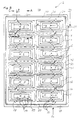
- Fig. 2 shows a schematic plan view of a pallet 2 of a second embodiment the invention.
- the components with the same functions as in FIG. 1 are identified by the same reference numerals and are not discussed separately.
- the pallet 2 has step-pyramid-shaped steps arranged in rows 22 and columns 23 Wells 5.
- These step pyramid-shaped depressions 5 can be in each their levels 7 and 8 items with different dimensions sort and arrange to store them in the pallet and / or with the pallet transport.
- each of the pyramid levels 7 and 8 has contact surfaces that the edge contours of the objects are adapted, being in the step pyramid Deepening of a lower pyramid level 7 compared to one pyramid step 8 arranged above it, bearing surfaces 6 with smaller dimensions are in place to level the objects according to their height Sort and arrange external dimensions in the recesses.
- the wells 5 are turned in from an upper side 30 and form between the pyramid steps 7 and 8 turned walls so that the objects in the wells of the pallet are arranged, are protected from damage.
- the top 30 also forms a stable frame for the entire range, and outer walls 20 connect the top 30 with a pallet foot 29, the one circumferential collar of the pallet 2 forms. Because of the spreading down Outer walls 20 of the pallet 2 are the pallets which are equipped without objects one inside the other stackable and can thus be stored in a space-saving manner.
- the pallet shown in FIG. 2 is suitable for blades of an axially flow-through turbomachine take.
- the contact surfaces on the contours of the Blades adjusted so that the individual pyramid levels 7 and 8 are not horizontal run, but the spatial edge contour of each blade is adjusted in every detail are.
- the pallet shown in Fig. 2 has 2 vertically aligned grooves 16 in each well. These grooves 16 are designed such that they the sealing plates each blade separating the airfoil area from the blade root area separate, can record. At the same time, these grooves represent 16 guide grooves, the crucial when sorting and inserting the objects into the pallet 2 are and clear yes and no decisions for a tiered arrangement of the Allow buckets in pallet 2.
- an opening 15 is arranged for draining of moisture and condensation. Even if the is not stored stocked pallet 2 in the outside areas of a plant can rainwater over these openings 15 run off, and thus the depressions 5 can be kept dry become. On the other hand, it is possible to use the depressions 5 for a purge gas flow through the wells of contaminated objects to be stored freed.
- the objects to be stored in an inert gas atmosphere or should hold under vacuum the opening 15 of the evacuation or serve the inert gas filling.
- the objects to be stored are under vacuum or packed in inert gas, such pallets 2 have no openings 15 at lowest point of depression 5.
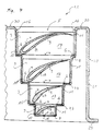
- Fig. 3 shows a schematic cross-sectional view of a portion of a with blades 9 loaded pallet 2 of the second embodiment of the invention along the Section line A-A of Fig. 2.
- the components with the same functions as in previous ones Figures are identified with the same reference numerals and not specifically discussed.
- the section line A-A in FIG. 2 lies axially in the blade area 19 of the blades flowed through flow machine, which in the recesses 5 of the pallet 2nd are arranged for sorting, storing or transporting.
- the turned-in walls 14, which connect the individual pyramid levels 7 and 8, have in this Embodiment of the invention its largest external dimensions in the area of the sealing plates 17 of the blades, the airfoil area 19 from that not seen in FIG. 3 Separate the blade root area.
- the sealing plate 17 is only partially visible in FIG. 3 and thus their outer edges are partially shown in Fig. 3 with dashed lines.
- the contact surfaces 6 are the spatial edge contours of the airfoil adjusted in the area of the blade leading edge 10 and the blade trailing edge 11.
- the contact surface 6 for the blade leading edge 10 is opposite the contact surface 6 of the blade trailing edge 11 are arranged lower in each of the pyramid steps, so that the heavier and more resilient blade leading edge 10 fully conform Support surface 6 rests, while in the area of the rear edge 11 a recess 25 of the support surface 6 ensures that the rear edge 11 is supported freely floating becomes.
- the top 30 merges into an outer wall 20 which is trapezoidal in cross section extends to a pallet foot 29 and thus a support frame 21 forms for the pallet 20.
- the inclined outer wall 20 and the step pyramid-shaped Recess 5 form a pallet 2, which can be stacked with other pallets is as long as it is not equipped with objects 3.
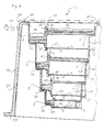
- Fig. 4 shows a schematic cross-sectional view of a portion of a with blades 9 loaded pallet 2 of the second embodiment of the invention along the Section line B-B of Fig. 2.
- the components with the same functions as in previous ones Figures are identified with the same reference numerals and not specifically discussed.
- the section line B-B is laid in Fig. 2 such that it cuts the vertical grooves 16, so that the track of the airfoil 9 on the sealing surface 17 is visible is and the support of the sealing plate 17 in the vertical grooves 16 and on the Pyramid levels 7 and 8 becomes visible. While the top two blades 9 one axially flow-through flow machine form hollow blades so that over the Cavity of the blades are a cooling gas can be passed in turbine operation the lower two pyramid levels are provided for blades in this embodiment, that have no cavity. A comparison of FIGS.
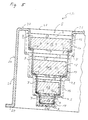
- Fig. 5 shows a schematic cross-sectional view of a portion of a with blades 9 loaded pallet 2 of the second embodiment of the invention along the Section line C-C of Fig. 2.
- the components with the same functions as in previous ones Figures are identified with the same reference numerals and not specifically discussed.
- the section line C-C in Fig. 2 is such that in Fig. 5 is a cross-sectional view can be seen in the foot region 18 of a blade 9.
- the blade feet 12 are from the support surfaces 6 in the foot region 18 are supported by each pyramid level 7 and 8, that they experience an almost horizontal orientation.
- the cross-sectional area of the blade root 12 is smaller than the cross-sectional area of the sealing plate 17, which is therefore partially marked with dashed lines in Fig. 5 in its outline.
- the drainage opening 15 is consequently in the area of the lowest sealing plate and at the same time forms the deepest point of depression 5.
- Fig. 6 shows a schematic cross-sectional view of a portion of a with blades 9 loaded pallet 2 of the second embodiment of the invention along the Section line D-D of Fig. 2.
- the components with the same functions as in previous ones Figures are identified with the same reference numerals and not specifically discussed.
- the section line D-D in Fig. 2 is arranged such that it is equipped with blades Indentation 5 shows in the direction of the longitudinal axis of the blades.
- the contact surfaces 6 thus support the blade root area 18 and the blade area on the one hand 19 at their respective edges, with the blade leading edge 10 deeper in each
- the pyramid level is arranged as the trailing edge of the blade, which is not visible in this figure.
- the sealing plate of each blade is arranged in vertical grooves 16.
- Fig. 6 also shows with dash-dotted lines a cover plate 26, the top 30 of the pallet 2 can cover.
- This cover plate 26 has in its edge area a collar 27 with a ring shoulder 28.
- This ring approach ensures alignment and sealing the top plate 26 from the top 30 of the pallet 2.
- the collar 27 of the cover plate 26 can serve to put loaded pallets 2 on top of each other to stack in such a way that the pallet foot 29 is centered by the ring approach 28 is worn by the collar 27. In this way, the cover plate 26 not only for covering the depressions 5 of the pallet 2, but also serves at the same time the stackability of loaded pallets 2.
Landscapes
- Engineering & Computer Science (AREA)
- Mechanical Engineering (AREA)
- General Engineering & Computer Science (AREA)
- Pallets (AREA)
- Packaging Of Annular Or Rod-Shaped Articles, Wearing Apparel, Cassettes, Or The Like (AREA)
- Packaging Of Machine Parts And Wound Products (AREA)
- Turbine Rotor Nozzle Sealing (AREA)
Abstract
Description
- Fig. 1
- zeigt eine schematische Querschnittsansicht eines Behältnisses einer ersten Ausführungsform der Erfindung.
- Fig. 2
- zeigt eine schematische Draufsicht auf eine Palette einer zweiten Ausführungsform der Erfindung.
- Fig. 3
- zeigt eine schematische Querschnittsansicht eines Abschnitts einer mit Schaufeln bestückten Palette der zweiten Ausführungsform der Erfindung entlang der Schnittlinie A-A der Fig. 2.
- Fig. 4
- zeigt eine schematische Querschnittsansicht eines Abschnitts einer mit Schaufeln bestückten Palette der zweiten Ausführungsform der Erfindung entlang der Schnittlinie B-B der Fig. 2.
- Fig. 5
- zeigt eine schematische Querschnittsansicht eines Abschnitts einer mit Schaufeln bestückten Palette der zweiten Ausführungsform der Erfindung entlang der Schnittlinie C-C der Fig. 2.
- Fig. 6
- zeigt eine schematische Querschnittsansicht eines Abschnitts einer mit Schaufeln bestückten Palette der zweiten Ausführungsform der Erfindung entlang der Schnittlinie D-D der Fig. 2.
- 1
- Behältnis
- 2
- Palette
- 3
- Gegenstand
- 4
- Randkontur
- 5
- Vertiefung
- 6
- Auflagefläche
- 7
- Pyramidenstufe
- 8
- darüber angeordnete Pyramidenstufe
- 9
- Schaufel
- 10
- Schaufelvorderkante
- 11
- Schaufelhinterkante
- 12
- Schaufelfuß
- 13
- Tannenbaumprofil
- 14
- Wandung
- 15
- Öffnung
- 16
- vertikale Nuten
- 17
- Dichtplatte
- 18
- Schaufelfußbereich
- 19
- Schaufelblattbereich
- 20
- Außenwand
- 21
- Tragrahmen
- 22
- Zeilen
- 23
- Spalten
- 24
- Außenrand
- 25
- Ausnehmung
- 26
- Deckplatte
- 27
- Kragen
- 28
- Ringansatz
- 29
- Palettenfuß
- 30
- Oberseite der Palette
Claims (30)
- Behältnis zur Aufnahme von Schaufeln (9) einer Strömungsmaschine mit voneinander unterschiedlichen Außenabmessungen und Randkonturen (4), wobei das Behältnis (1) mindestens eine stufenpyramidenförmige Vertiefung (5) mit Auflageflächen (6) aufweist und in der stufenpyramidenförmigen Vertiefung (5) eine tiefer angeordnete Pyramidenstufe (7) gegenüber einer darüber angeordneten Pyramidenstufe (8) Auflageflächen (6) mit geringeren Abmessungen aufweist, um die Gegenstände (3) höhengestaffelt entsprechend ihren Außenabmessungen in der Vertiefung (5) aufzunehmen.
- Behältnis nach Anspruch 1, dadurch gekennzeichnet, dass die Auflageflächen (6) an Konturen (4) von Schaufeln (9) mit voneinander unterschiedlichen Außenabmessungen und spatialen Randkonturen (4) einer axial durchströmten Strömungsmaschine angepasst sind.
- Behältnis nach Anspruch 1 oder Anspruch 2, dadurch gekennzeichnet, dass die Auflageflächen (6) der stufenpyramidenförmigen Vertiefung (5) derartig ausgestaltet sind, dass sie voneinander unterschiedlich große Schaufeln (9) einer axial durchströmten Strömungsmaschine in der Weise stützen, dass eine Schaufelvorderkante (10) tiefer angeordnet ist, als eine zugehörige Schaufelhinterkante (11).
- Behältnis nach einem der vorhergehenden Ansprüche, dadurch gekennzeichnet, dass horizontal ausgebildete Auflageflächen (6) zur Stützung eines an der Schaufel (9) ausgebildeten Schaufelfußes (12) vorgesehen sind.
- Behältnis nach einem der vorhergehenden Ansprüche, dadurch gekennzeichnet, dass die Auflageflächen (6) der stufenpyramidenförmigen Vertiefung (5) derartig ausgestaltet sind, dass sie voneinander unterschiedlich große Schaufeln (9) einer axial durchströmten Strömungsmaschine in der Weise stützen, dass deren Schaufelhinterkanten (11) freischwebend stützbar sind.
- Behältnis nach einem der vorhergehenden Ansprüche, dadurch gekennzeichnet, dass das Behältnis (1) ein einstückiges Tiefziehteil ist.
- Behältnis nach einem der vorhergehenden Ansprüche, dadurch gekennzeichnet, dass das Behältnis (1) ein einstückiges Spritzgussteil ist.
- Behältnis nach einem der vorhergehenden Ansprüche, dadurch gekennzeichnet, dass das Behältnis (1) eine Kunststoffmasse aufweist.
- Behältnis nach einem der vorhergehenden Ansprüche, dadurch gekennzeichnet, dass das Behältnis (1) ein Polymer der Gruppe Polyethylen, Polyvinylchlorid, Polystyrol, Polypropylen, Polyimid und/oder Mischungen derselben aufweist.
- Behältnis nach einem der vorhergehenden Ansprüche, dadurch gekennzeichnet, dass das Behältnis (1) aus einer tiefziehbaren Kunststoffplatte herstellbar ist.
- Behältnis nach einem der vorhergehenden Ansprüche, dadurch gekennzeichnet, dass die Vertiefung (5) eine in das Innere des Behältnisses (1) gestülpte Wandung (14) zwischen den Pyramidenstufen (7, 8) aufweist.
- Behältnis nach einem der vorhergehenden Ansprüche, dadurch gekennzeichnet, dass das Behältnis (1) im untersten Bereich der Vertiefung (5) eine Öffnung (15) aufweist.
- Behältnis nach einem der vorhergehenden Ansprüche, dadurch gekennzeichnet, dass das Behältnis (1) von Pyramidenstufe (7, 8) zu Pyramidenstufe (7, 8) vertikal erstreckende Nuten (16) aufweist, die Konturen von Dichtplatten (17) zwischen Schaufelfußbereich (18) und Schaufelblattbereich (19) von Schaufeln (9) einer axial durchströmten Strömungsmaschine angepasst sind.
- Behältnis nach einem der vorhergehenden Ansprüche, dadurch gekennzeichnet, dass das Behältnis (1) Außenwände (20) aufweist, welche die Vertiefung (5) umgeben und im Querschnitt einen trapezförmigen Tragrahmen (21) bilden.
- Palette, zur Aufnahme von Schaufeln einer Strömungsmaschine (3) mit voneinander unterschiedlichen Außenabmessungen und Randkonturen (4), wobei die Palette (2) in Zeilen (22) und Spalten (23) angeordnete stufenpyramidenförmige Vertiefungen (5) mit Auflageflächen aufweist und in jeder stufenpyramidenförmigen Vertiefung (5) eine tiefer angeordnete Pyramidenstufe (7) gegenüber einer darüber angeordneten Pyramidenstufe (8) Auflageflächen (6) mit geringeren Abmessungen aufweist, um die Schaufeln höhengestaffelt entsprechend ihren Außenabmessungen in den Vertiefungen (5) aufzunehmen.
- Palette nach Anspruch 15, dadurch gekennzeichnet, dass die Auflageflächen(6) an Konturen (4) von Schaufeln (9) mit voneinander unterschiedlichen Außenabmessungen und spatialen Randkonturen (4) einer axial durchströmten Strömungsmaschine angepasst sind.
- Palette nach Anspruch 15 oder Anspruch 16, dadurch gekennzeichnet, dass die Auflageflächen (6)der stufenpyramidenförmigen Vertiefungen (5) derartig ausgestaltet sind, dass sie voneinander unterschiedlich große Schaufeln (9) einer axial durchströmten Strömungsmaschine in der Weise stützen, dass eine Schaufelvorderkante (10) tiefer angeordnet ist, als eine zugehörige Schaufelhinterkante (11).
- Palette nach einem der Ansprüche 15 bis 17, dadurch gekennzeichnet, dass horizontal ausgebildete Auflageflächen (6) zur Stützung eines an der Schaufel (9) ausgebildeten Schaufelfußes (12) vorgesehen sind.
- Palette nach einem der Ansprüche 15 bis 18, dadurch gekennzeichnet, dass die Auflageflächen (6) der stufenpyramidenförmigen Vertiefungen (5) derartig ausgestaltet sind, dass sie voneinander unterschiedlich große Schaufeln (9) einer axial durchströmten Strömungsmaschine in der Weise stützen, dass deren Schaufelhinterkanten (11) freischwebend stützbar sind.
- Palette nach einem der Ansprüche 15 bis 19, dadurch gekennzeichnet, dass die Palette (2) ein einstückiges Tiefziehteil ist.
- Palette nach einem der Ansprüche 15 bis 19, dadurch gekennzeichnet, dass die Palette (2) ein einstückiges Spritzgussteil ist.
- Palette nach einem der Ansprüche 15 bis 21, dadurch gekennzeichnet, dass die Palette (2) eine Kunststoffmasse aufweist.
- Palette nach einem der Ansprüche 15 bis 22, dadurch gekennzeichnet, dass die Palette (2) ein Polymer der Gruppe Polyethylen, Polyvinylchlorid, Polystyrol, Polypropylen, Polyimid und/oder Mischungen derselben aufweist.
- Palette nach einem der Ansprüche 15 bis 23, dadurch gekennzeichnet, dass die Palette (2) aus einer tiefziehbaren Kunststoffplatte herstellbar ist.
- Palette nach einem der Ansprüche 15 bis 24, dadurch gekennzeichnet, dass die Vertiefungen (5) in das Innere der Palette (2) gestülpte Wandungen (14) zwischen den Pyramidenstufen (7, 8) aufweist.
- Palette nach einem der Ansprüche 15 bis 25, dadurch gekennzeichnet, dass die Palette (2) im untersten Bereich der Vertiefungen (5) jeweils eine Öffnung (15) aufweisen.
- Palette nach einem der Ansprüche 15 bis 26, dadurch gekennzeichnet, dass die Palette (2) von Pyramidenstufe (7, 8) zu Pyramidenstufe (7, 8) vertikal erstreckende Nuten (16) aufweist, die Konturen von Dichtplatten (17) zwischen Schaufelfußbereich (18) und Schaufelblattbereich (19) von Schaufeln (9) einer axial durchströmten Strömungsmaschine angepasst sind.
- Palette nach einem der Ansprüche 15 bis 27, dadurch gekennzeichnet, dass die Palette (2) einen Außenrand (24) aufweist, welche die Vertiefungen (5) umgeben und stützen und im Querschnitt einen trapezförmigen Tragrahmen (21) bilden.
- Palette nach einem der Ansprüche 15 bis 28, dadurch gekennzeichnet, dass die Palette (2) einen abnehmbare Deckplatte mit einem umlaufenden horizontalen Kragen aufweist.
- Palette nach Anspruch 29, dadurch gekennzeichnet, dass der umlaufende Kragen der Deckplatte einen Ringansatz aufweist, der dem Grundriss des Tragrahmen (21) zur Stapelung von mit Schaufeln (3) bestückten Paletten (2) angepasst ist.
Applications Claiming Priority (2)
| Application Number | Priority Date | Filing Date | Title |
|---|---|---|---|
| DE10214161A DE10214161C1 (de) | 2002-03-28 | 2002-03-28 | Behältnis und Palette zur Aufnahme von Schaufeln einer Strömungsmaschine |
| DE10214161 | 2002-03-28 |
Publications (2)
| Publication Number | Publication Date |
|---|---|
| EP1348643A1 true EP1348643A1 (de) | 2003-10-01 |
| EP1348643B1 EP1348643B1 (de) | 2005-11-23 |
Family
ID=7714253
Family Applications (1)
| Application Number | Title | Priority Date | Filing Date |
|---|---|---|---|
| EP03006630A Expired - Lifetime EP1348643B1 (de) | 2002-03-28 | 2003-03-24 | Behältnis und Palette zur Aufnahme von Schaufeln einer Strömungsmaschine |
Country Status (4)
| Country | Link |
|---|---|
| US (2) | US20040060839A1 (de) |
| EP (1) | EP1348643B1 (de) |
| AT (1) | ATE310688T1 (de) |
| DE (2) | DE10214161C1 (de) |
Families Citing this family (9)
| Publication number | Priority date | Publication date | Assignee | Title |
|---|---|---|---|---|
| ES2253122B1 (es) * | 2004-11-11 | 2007-08-01 | Gamesa Eolica, S.A. Sociedad Unipersonal | Contenedor para el transporte de palas. |
| US8632286B2 (en) * | 2006-04-28 | 2014-01-21 | General Electric Company | Transportation unit for a wind turbine rotor blade |
| US20080099358A1 (en) * | 2006-10-25 | 2008-05-01 | United Technologies Corporation | Blade handling tray insert |
| JP5156261B2 (ja) * | 2007-04-27 | 2013-03-06 | キョーラク株式会社 | パレット |
| US8733549B2 (en) * | 2007-11-13 | 2014-05-27 | General Electric Company | System for containing and/or transporting wind turbine components |
| US8342491B2 (en) * | 2009-04-01 | 2013-01-01 | Vestas Wind Systems A/S | Transport system for transportation of a spar |
| JP2013513051A (ja) * | 2009-12-03 | 2013-04-18 | シーメンス アクティエンゲゼルシャフト | 適応性のある輸送パッケージ |
| DE102011054682A1 (de) * | 2011-10-21 | 2013-04-25 | Lapp Engineering & Co. | Lager- und Transportpalette |
| GB201807969D0 (en) * | 2018-05-16 | 2018-07-04 | Quality Hospital Solutions Ltd | Improved container storage device |
Citations (6)
| Publication number | Priority date | Publication date | Assignee | Title |
|---|---|---|---|---|
| US2865500A (en) * | 1955-09-06 | 1958-12-23 | Parsons Corp | Shock-absorbing shipping assembly for rotor blades |
| US3136413A (en) * | 1961-02-13 | 1964-06-09 | Westinghouse Electric Corp | Container |
| DE3310811A1 (de) * | 1983-03-24 | 1984-09-27 | Siemens AG, 1000 Berlin und 8000 München | Transportpalette |
| WO1996024530A1 (en) * | 1995-02-09 | 1996-08-15 | David S. Smith Packaging Limited | Pallet for carrying toroidal objects |
| US5934471A (en) * | 1997-01-28 | 1999-08-10 | Samsung Electronics Co., Ltd. | Stackable tray for containing offset parts |
| JP2000238849A (ja) * | 1999-02-25 | 2000-09-05 | Zeon Kasei Co Ltd | 梱包用積層緩衝体 |
Family Cites Families (21)
| Publication number | Priority date | Publication date | Assignee | Title |
|---|---|---|---|---|
| US2438434A (en) * | 1945-02-20 | 1948-03-23 | Friedman Theodore | Collapsible container |
| US2764334A (en) * | 1952-09-18 | 1956-09-25 | Walter J Schwertfeger | Container for eggs and method of assembly with egg-containing fillers |
| US3009603A (en) * | 1958-06-16 | 1961-11-21 | Illinois Tool Works | Plastic flower pot |
| US3168953A (en) * | 1961-08-30 | 1965-02-09 | Gen Electric | Electron tube package |
| DE1264750B (de) * | 1965-09-03 | 1968-03-28 | Bayer Ag | Verwendung bestimmter Trioxanmischpolymerisate zum Extrudieren bzw. Tiefziehen |
| US3484035A (en) * | 1968-01-08 | 1969-12-16 | Dart Ind Inc | Multipurpose container |
| US3932575A (en) * | 1972-04-06 | 1976-01-13 | Sven Ingemar Andersson | Method of making a multilayered packaging tray by deep-drawing |
| US3771646A (en) * | 1972-06-28 | 1973-11-13 | Plastofilm Ind Inc | Shipping holder for spark plugs or the like |
| JPS52144061A (en) * | 1976-05-27 | 1977-12-01 | Sumitomo Bakelite Co | Method and device for thermally forming plastic sheet |
| US4834239A (en) * | 1988-03-01 | 1989-05-30 | Packaging Industries Group, Inc. | Package for fluorescent lamps |
| US4840276A (en) * | 1988-05-25 | 1989-06-20 | George & Thomas Cone Company | Cone package |
| US4978007A (en) * | 1989-05-10 | 1990-12-18 | Minnesota Mining And Manufacturing Company | Packaging curable materials |
| US5106297A (en) * | 1990-10-22 | 1992-04-21 | Centrix, Inc. | Dental bonding liquid and sealant tray |
| JP2917621B2 (ja) * | 1991-11-08 | 1999-07-12 | 松下電器産業株式会社 | 電解コンデンサの包装装置 |
| CH684081A5 (de) * | 1991-11-18 | 1994-07-15 | Alusuisse Lonza Services Ag | Durchdrückpackung. |
| DE9204751U1 (de) * | 1992-04-06 | 1992-06-17 | Patent-Treuhand-Gesellschaft für elektrische Glühlampen mbH, 8000 München | Palette |
| DE4240327C2 (de) * | 1992-12-01 | 1994-10-13 | Berner Kunststofftech Gmbh | Verpackung aus Kunststoff mit Originalitätsverschluß |
| US5413054A (en) * | 1993-06-28 | 1995-05-09 | Collins; Eric H. | Plastic cradle pallet for loading, storing and transporting heavy steel or other metal coils in a vertical position |
| DE19751759C1 (de) * | 1997-11-21 | 1999-05-20 | Kaldewei Franz Gmbh & Co | Verfahren zur Herstellung einer Verbundwanne |
| US6357366B1 (en) * | 1999-02-05 | 2002-03-19 | Menasha Corporation | Rackable molded pallet |
| US6497338B1 (en) * | 2000-08-15 | 2002-12-24 | Michael D. Stolzman | Plastic drum with reinforced sidewall |
-
2002
- 2002-03-28 DE DE10214161A patent/DE10214161C1/de not_active Expired - Fee Related
-
2003
- 2003-03-24 AT AT03006630T patent/ATE310688T1/de not_active IP Right Cessation
- 2003-03-24 DE DE50301712T patent/DE50301712D1/de not_active Expired - Lifetime
- 2003-03-24 EP EP03006630A patent/EP1348643B1/de not_active Expired - Lifetime
- 2003-03-27 US US10/400,555 patent/US20040060839A1/en not_active Abandoned
-
2007
- 2007-08-07 US US11/890,679 patent/US20080028726A1/en not_active Abandoned
Patent Citations (6)
| Publication number | Priority date | Publication date | Assignee | Title |
|---|---|---|---|---|
| US2865500A (en) * | 1955-09-06 | 1958-12-23 | Parsons Corp | Shock-absorbing shipping assembly for rotor blades |
| US3136413A (en) * | 1961-02-13 | 1964-06-09 | Westinghouse Electric Corp | Container |
| DE3310811A1 (de) * | 1983-03-24 | 1984-09-27 | Siemens AG, 1000 Berlin und 8000 München | Transportpalette |
| WO1996024530A1 (en) * | 1995-02-09 | 1996-08-15 | David S. Smith Packaging Limited | Pallet for carrying toroidal objects |
| US5934471A (en) * | 1997-01-28 | 1999-08-10 | Samsung Electronics Co., Ltd. | Stackable tray for containing offset parts |
| JP2000238849A (ja) * | 1999-02-25 | 2000-09-05 | Zeon Kasei Co Ltd | 梱包用積層緩衝体 |
Non-Patent Citations (1)
| Title |
|---|
| PATENT ABSTRACTS OF JAPAN vol. 2000, no. 12 3 January 2001 (2001-01-03) * |
Also Published As
| Publication number | Publication date |
|---|---|
| DE10214161C1 (de) | 2003-05-28 |
| ATE310688T1 (de) | 2005-12-15 |
| US20040060839A1 (en) | 2004-04-01 |
| DE50301712D1 (de) | 2005-12-29 |
| EP1348643B1 (de) | 2005-11-23 |
| US20080028726A1 (en) | 2008-02-07 |
Similar Documents
| Publication | Publication Date | Title |
|---|---|---|
| DE69426241T2 (de) | Ineinandersetzbare displaysteige für flaschen | |
| DE69319086T2 (de) | Niedrige,ineinander spapelbare tragschale zur aufnahme von dosen oder dergleichen | |
| EP2251184B1 (de) | Verfahren zur Herstellung eines Transport- und Lagermittels sowie ein zur Durchführung des Verfahrens ausgebildetes Transport- und Lagermittel | |
| DE69321363T2 (de) | Flaschenkastenanordnung | |
| DE102013009340A1 (de) | Einrichtung und Verfahren zum Ein- und Auslagern von stapelbaren Behältern | |
| DE202010005090U1 (de) | Transportbox | |
| EP1348643B1 (de) | Behältnis und Palette zur Aufnahme von Schaufeln einer Strömungsmaschine | |
| DE102008011537A1 (de) | Transportmittel aus Kunststoff | |
| EP2794410B1 (de) | Stapelkanister | |
| EP0901967A2 (de) | Stapelbarer Flaschenträger | |
| DE102017106898B4 (de) | Verpackungsmaschine mit stapelbaren Schutzabdeckungen | |
| EP0277307B1 (de) | Transport-, Lager- und Stapelvorrichtung | |
| DE19927069C2 (de) | Transportbehälter | |
| DE69505317T2 (de) | Stapel von Gegenständen zur Lagerung und/oder zum Transport | |
| EP0285759A1 (de) | Palette zum Speichern und zum Transport von Warenstücken | |
| DE202016105636U1 (de) | Mehrweg-Behälter zum Lagern und Transportieren von Lebensmitteln | |
| DE102010040918B4 (de) | Behälter zum Stapeln und Transportieren von Scheiben aus brüchigem Material | |
| DE3518251C2 (de) | ||
| EP1608562B1 (de) | Ladeeinheit mit palettiertablar | |
| DE10028588B4 (de) | Stapelbares Transportgebinde für stapelbares Stückgut | |
| DE10203716C1 (de) | Pflanz-oder Kulturgefäß aus faserigen, biologisch abbaubaren Werkstoffen, insbesondere aus Kokosnussfasern | |
| DE20215803U1 (de) | Träger zur Aufnahme einer Vielzahl von Behältern | |
| DE69009997T2 (de) | Stapelbarer kasten. | |
| DE69935444T2 (de) | Verbesserter pipettenspitzen-aufnahmebehälter | |
| DE4209781A1 (de) | Container |
Legal Events
| Date | Code | Title | Description |
|---|---|---|---|
| PUAI | Public reference made under article 153(3) epc to a published international application that has entered the european phase |
Free format text: ORIGINAL CODE: 0009012 |
|
| AK | Designated contracting states |
Kind code of ref document: A1 Designated state(s): AT BE BG CH CY CZ DE DK EE ES FI FR GB GR HU IE IT LI LU MC NL PT RO SE SI SK TR |
|
| AX | Request for extension of the european patent |
Extension state: AL LT LV MK |
|
| 17P | Request for examination filed |
Effective date: 20040331 |
|
| AKX | Designation fees paid |
Designated state(s): AT BE BG CH CY CZ DE DK EE ES FI FR GB GR HU IE IT LI LU MC NL PT RO SE SI SK TR |
|
| 17Q | First examination report despatched |
Effective date: 20040907 |
|
| GRAP | Despatch of communication of intention to grant a patent |
Free format text: ORIGINAL CODE: EPIDOSNIGR1 |
|
| GRAS | Grant fee paid |
Free format text: ORIGINAL CODE: EPIDOSNIGR3 |
|
| GRAA | (expected) grant |
Free format text: ORIGINAL CODE: 0009210 |
|
| AK | Designated contracting states |
Kind code of ref document: B1 Designated state(s): AT BE BG CH CY CZ DE DK EE ES FI FR GB GR HU IE IT LI LU MC NL PT RO SE SI SK TR |
|
| PG25 | Lapsed in a contracting state [announced via postgrant information from national office to epo] |
Ref country code: IT Free format text: LAPSE BECAUSE OF FAILURE TO SUBMIT A TRANSLATION OF THE DESCRIPTION OR TO PAY THE FEE WITHIN THE PRESCRIBED TIME-LIMIT;WARNING: LAPSES OF ITALIAN PATENTS WITH EFFECTIVE DATE BEFORE 2007 MAY HAVE OCCURRED AT ANY TIME BEFORE 2007. THE CORRECT EFFECTIVE DATE MAY BE DIFFERENT FROM THE ONE RECORDED. Effective date: 20051123 Ref country code: SI Free format text: LAPSE BECAUSE OF FAILURE TO SUBMIT A TRANSLATION OF THE DESCRIPTION OR TO PAY THE FEE WITHIN THE PRESCRIBED TIME-LIMIT Effective date: 20051123 Ref country code: SK Free format text: LAPSE BECAUSE OF FAILURE TO SUBMIT A TRANSLATION OF THE DESCRIPTION OR TO PAY THE FEE WITHIN THE PRESCRIBED TIME-LIMIT Effective date: 20051123 Ref country code: IE Free format text: LAPSE BECAUSE OF FAILURE TO SUBMIT A TRANSLATION OF THE DESCRIPTION OR TO PAY THE FEE WITHIN THE PRESCRIBED TIME-LIMIT Effective date: 20051123 Ref country code: FI Free format text: LAPSE BECAUSE OF FAILURE TO SUBMIT A TRANSLATION OF THE DESCRIPTION OR TO PAY THE FEE WITHIN THE PRESCRIBED TIME-LIMIT Effective date: 20051123 Ref country code: RO Free format text: LAPSE BECAUSE OF FAILURE TO SUBMIT A TRANSLATION OF THE DESCRIPTION OR TO PAY THE FEE WITHIN THE PRESCRIBED TIME-LIMIT Effective date: 20051123 Ref country code: NL Free format text: LAPSE BECAUSE OF FAILURE TO SUBMIT A TRANSLATION OF THE DESCRIPTION OR TO PAY THE FEE WITHIN THE PRESCRIBED TIME-LIMIT Effective date: 20051123 Ref country code: CZ Free format text: LAPSE BECAUSE OF FAILURE TO SUBMIT A TRANSLATION OF THE DESCRIPTION OR TO PAY THE FEE WITHIN THE PRESCRIBED TIME-LIMIT Effective date: 20051123 |
|
| REG | Reference to a national code |
Ref country code: GB Ref legal event code: FG4D Free format text: NOT ENGLISH |
|
| REG | Reference to a national code |
Ref country code: CH Ref legal event code: EP |
|
| REF | Corresponds to: |
Ref document number: 50301712 Country of ref document: DE Date of ref document: 20051229 Kind code of ref document: P |
|
| REG | Reference to a national code |
Ref country code: IE Ref legal event code: FG4D Free format text: LANGUAGE OF EP DOCUMENT: GERMAN |
|
| GBT | Gb: translation of ep patent filed (gb section 77(6)(a)/1977) |
Effective date: 20060107 |
|
| PG25 | Lapsed in a contracting state [announced via postgrant information from national office to epo] |
Ref country code: SE Free format text: LAPSE BECAUSE OF FAILURE TO SUBMIT A TRANSLATION OF THE DESCRIPTION OR TO PAY THE FEE WITHIN THE PRESCRIBED TIME-LIMIT Effective date: 20060223 Ref country code: DK Free format text: LAPSE BECAUSE OF FAILURE TO SUBMIT A TRANSLATION OF THE DESCRIPTION OR TO PAY THE FEE WITHIN THE PRESCRIBED TIME-LIMIT Effective date: 20060223 Ref country code: BG Free format text: LAPSE BECAUSE OF FAILURE TO SUBMIT A TRANSLATION OF THE DESCRIPTION OR TO PAY THE FEE WITHIN THE PRESCRIBED TIME-LIMIT Effective date: 20060223 Ref country code: GR Free format text: LAPSE BECAUSE OF FAILURE TO SUBMIT A TRANSLATION OF THE DESCRIPTION OR TO PAY THE FEE WITHIN THE PRESCRIBED TIME-LIMIT Effective date: 20060223 |
|
| PG25 | Lapsed in a contracting state [announced via postgrant information from national office to epo] |
Ref country code: ES Free format text: LAPSE BECAUSE OF FAILURE TO SUBMIT A TRANSLATION OF THE DESCRIPTION OR TO PAY THE FEE WITHIN THE PRESCRIBED TIME-LIMIT Effective date: 20060306 |
|
| PG25 | Lapsed in a contracting state [announced via postgrant information from national office to epo] |
Ref country code: AT Free format text: LAPSE BECAUSE OF NON-PAYMENT OF DUE FEES Effective date: 20060324 |
|
| PG25 | Lapsed in a contracting state [announced via postgrant information from national office to epo] |
Ref country code: BE Free format text: LAPSE BECAUSE OF NON-PAYMENT OF DUE FEES Effective date: 20060331 Ref country code: MC Free format text: LAPSE BECAUSE OF NON-PAYMENT OF DUE FEES Effective date: 20060331 Ref country code: LU Free format text: LAPSE BECAUSE OF NON-PAYMENT OF DUE FEES Effective date: 20060331 |
|
| PG25 | Lapsed in a contracting state [announced via postgrant information from national office to epo] |
Ref country code: PT Free format text: LAPSE BECAUSE OF FAILURE TO SUBMIT A TRANSLATION OF THE DESCRIPTION OR TO PAY THE FEE WITHIN THE PRESCRIBED TIME-LIMIT Effective date: 20060424 |
|
| NLV1 | Nl: lapsed or annulled due to failure to fulfill the requirements of art. 29p and 29m of the patents act | ||
| PG25 | Lapsed in a contracting state [announced via postgrant information from national office to epo] |
Ref country code: HU Free format text: LAPSE BECAUSE OF FAILURE TO SUBMIT A TRANSLATION OF THE DESCRIPTION OR TO PAY THE FEE WITHIN THE PRESCRIBED TIME-LIMIT Effective date: 20060524 |
|
| REG | Reference to a national code |
Ref country code: IE Ref legal event code: FD4D |
|
| ET | Fr: translation filed | ||
| PLBE | No opposition filed within time limit |
Free format text: ORIGINAL CODE: 0009261 |
|
| STAA | Information on the status of an ep patent application or granted ep patent |
Free format text: STATUS: NO OPPOSITION FILED WITHIN TIME LIMIT |
|
| 26N | No opposition filed |
Effective date: 20060824 |
|
| REG | Reference to a national code |
Ref country code: CH Ref legal event code: PL |
|
| GBPC | Gb: european patent ceased through non-payment of renewal fee |
Effective date: 20070324 |
|
| BERE | Be: lapsed |
Owner name: HERGETH, WILLIBALD Effective date: 20060331 |
|
| PG25 | Lapsed in a contracting state [announced via postgrant information from national office to epo] |
Ref country code: LI Free format text: LAPSE BECAUSE OF NON-PAYMENT OF DUE FEES Effective date: 20070331 Ref country code: CH Free format text: LAPSE BECAUSE OF NON-PAYMENT OF DUE FEES Effective date: 20070331 |
|
| PG25 | Lapsed in a contracting state [announced via postgrant information from national office to epo] |
Ref country code: GB Free format text: LAPSE BECAUSE OF NON-PAYMENT OF DUE FEES Effective date: 20070324 |
|
| PG25 | Lapsed in a contracting state [announced via postgrant information from national office to epo] |
Ref country code: EE Free format text: LAPSE BECAUSE OF FAILURE TO SUBMIT A TRANSLATION OF THE DESCRIPTION OR TO PAY THE FEE WITHIN THE PRESCRIBED TIME-LIMIT Effective date: 20051123 |
|
| PG25 | Lapsed in a contracting state [announced via postgrant information from national office to epo] |
Ref country code: TR Free format text: LAPSE BECAUSE OF FAILURE TO SUBMIT A TRANSLATION OF THE DESCRIPTION OR TO PAY THE FEE WITHIN THE PRESCRIBED TIME-LIMIT Effective date: 20051123 |
|
| PG25 | Lapsed in a contracting state [announced via postgrant information from national office to epo] |
Ref country code: CY Free format text: LAPSE BECAUSE OF FAILURE TO SUBMIT A TRANSLATION OF THE DESCRIPTION OR TO PAY THE FEE WITHIN THE PRESCRIBED TIME-LIMIT Effective date: 20051123 |
|
| PGFP | Annual fee paid to national office [announced via postgrant information from national office to epo] |
Ref country code: FR Payment date: 20100505 Year of fee payment: 8 |
|
| PGFP | Annual fee paid to national office [announced via postgrant information from national office to epo] |
Ref country code: DE Payment date: 20110331 Year of fee payment: 9 |
|
| REG | Reference to a national code |
Ref country code: FR Ref legal event code: ST Effective date: 20111130 |
|
| PG25 | Lapsed in a contracting state [announced via postgrant information from national office to epo] |
Ref country code: FR Free format text: LAPSE BECAUSE OF NON-PAYMENT OF DUE FEES Effective date: 20110331 |
|
| REG | Reference to a national code |
Ref country code: DE Ref legal event code: R119 Ref document number: 50301712 Country of ref document: DE Effective date: 20121002 |
|
| PG25 | Lapsed in a contracting state [announced via postgrant information from national office to epo] |
Ref country code: DE Free format text: LAPSE BECAUSE OF NON-PAYMENT OF DUE FEES Effective date: 20121002 |