EP1346942B1 - Dispositif rampe superieure de cabine d'ascenseur - Google Patents
Dispositif rampe superieure de cabine d'ascenseur Download PDFInfo
- Publication number
- EP1346942B1 EP1346942B1 EP00985997A EP00985997A EP1346942B1 EP 1346942 B1 EP1346942 B1 EP 1346942B1 EP 00985997 A EP00985997 A EP 00985997A EP 00985997 A EP00985997 A EP 00985997A EP 1346942 B1 EP1346942 B1 EP 1346942B1
- Authority
- EP
- European Patent Office
- Prior art keywords
- car
- handrails
- rotating
- elevator
- pair
- Prior art date
- Legal status (The legal status is an assumption and is not a legal conclusion. Google has not performed a legal analysis and makes no representation as to the accuracy of the status listed.)
- Expired - Lifetime
Links
Images


Classifications
-
- B—PERFORMING OPERATIONS; TRANSPORTING
- B66—HOISTING; LIFTING; HAULING
- B66B—ELEVATORS; ESCALATORS OR MOVING WALKWAYS
- B66B5/00—Applications of checking, fault-correcting, or safety devices in elevators
- B66B5/0043—Devices enhancing safety during maintenance
- B66B5/005—Safety of maintenance personnel
- B66B5/0081—Safety of maintenance personnel by preventing falling by means of safety fences or handrails, being operable or not, mounted on top of the elevator car
Definitions
- the present invention relates to a car-top handrail unit for an elevator, which is provided on a car and surrounds a working area for carrying out maintenance and inspection work on the car.
- a member when carrying out maintenance and inspection on an elevator, a member a maintenance personnel steps onto the car and performs maintenance and inspection work on device(s) inside the hoistway or on car-top device(s).
- a car-top handrail unit is generally provided on the car.
- FIG. 10 is a perspective view showing, by way of example, a conventional car-top handrail unit for an elevator disclosed in Japanese Utility Model Publication No. 2-42704 .
- Fig. 11 is a side view showing the car-top handrail unit in Fig. 10 and
- Fig. 12 is a side view showing a state where the car-top handrail unit in Fig. 11 is folded away.
- a car-top handrail unit 2 provided on a car 1 is assembled at the time of performing maintenance and inspection work as shown in Fig. 10 and Fig. 11 .
- the car-top handrail unit 2 is, as shown in Fig. 12 , folded away and the height thereof is reduced.
- the structure is complicated and a large number of parts is required, with the result that costs are high.
- the handrail needs to be assembled and folded away at the time of performing maintenance and inspection work, increasing the time required for performing the maintenance and inspection work, with the result that the operational efficiency of the elevator is degraded.
- JP-A-4 292 386 discloses a safety fence for an elevator cage with the purpose to prevent the occurrence of a dangerous state during an inspection work through extension of a safety fence to a high level by extending the safety fence fixed to a cage, dividing it at the middle thereof into two sections and interconnecting the division parts through an axle to form a bendable shape.
- the present invention was made with a view to solving the above-mentioned problems, and the object of the invention is to create a car-top handrail unit for an elevator which can avoid interference with beams and device(s) positioned upward of the car, and which can decrease cost with a simple structure.
- a car-top handrail unit for an elevator which is provided on a car and surrounds a working area for performing maintenance and inspection work on the car, comprising: a pair of fixed handrails provided uprightly on the upper portion of the car being spaced apart from each other in the width direction of the car, each having one end portion positioned in the vicinity of the front end portion of the car and the other end portion positioned in a middle portion in the depth direction of the car; and a pair of rotating handrails each being capable of rotating between a closed position, in which the rotating handrails extend along the width direction of the car from the other end portions of the pair of fixed handrails and close the gap between the other end portions, and as such defining a working area with surface area, and an open position, in which the rotating handrails extend along the depth direction of the car from the other end portions of the pair of fixed handrails and as such enlarging the surface area of the working area.
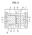
- Fig. 1 is a side view showing a car-top handrail unit for an elevator according to Embodiment 1 of the present invention and Fig. 2 is a cross-sectional diagram obtained by taking along a line II-II of Fig. 1 .
- a pair of guide rails 12 is provided within a hoistway 11.
- a car 13 ascends/descends within the hoistway 11 while being guided by the guide rails 12.
- Doors 14 and 15 of the car are respectively provided in the front and the back of the car 13.
- a beam 18 of the building used for lifting devices at the time of installation of the elevator, is installed upward of the car 13 within the hoistway 11.
- the car-top handrail unit 20 has a pair of fixed handrails 21 and 22 and a pair of rotating handrails 23 and 24.
- the fixed handrails 21 and 22 are provided uprightly on the upper portion of the car 13 being spaced apart from each other in the width direction of the car 13 (upper and lower direction in Fig. 2 ). Further, one end portion of each of the fixed handrails 21 and 22 is positioned in the vicinity of the front end portion of the car 13. The other end portions of the fixed handrails 21 and 22 are positioned in a middle portion in the depth direction (left and right direction in Fig. 2 ).
- the rotating handrails 23 and 24 each are capable of rotating between a closed position, in which they extend along the width direction of the car 13 from the other end portions of the pair of fixed handrails 21 and 22 and close the gap between the other end portions, and an open position, in which they extend along the depth direction of the car 13 from the other end portions of the pair of fixed handrails 21 and 22 as shown in Fig. 3 and Fig. 4 (a double door type).
- a member of maintenance personnel steps onto the car 13 from the landing on the front side of the car 13 (left side in Fig. 1 and Fig. 2 ).
- the rotating handrails 23 and 24 are in the closed position, work is performed within the working area A.
- maintenance personnel move to the working area B, as shown in Fig. 3 and Fig. 4 , the rotating handrails 23 and 24 rotate to the open position, once the car 13 has descended to a position at which the rotating handrails 23 and 24 will not interfere with the beam 18.
- the rotating handrails 23 and 24 do not interfere with the beam 18 or device(s) positioned upward of the car 13, as the rotating handrails 23 and 24 are rotated to the closed position.
- the beam 18 for lifting used when installing the elevator, can be removed after installation, this requires time and labor.
- the car-top handrail unit 20 does not interfere with the beam 18, meaning the beam 18 can be retained, and it becomes possible to eliminate the time and labor necessary for the removal of the beam.
- the car 13 can be suspended from the beam 18 at the time of exchanging the main rope (not shown) for suspending the car 13. Therefore, the time and labor involved in providing a new lifting member can be eliminated, enhancing the workability of maintenance work.
- Fig. 5 is a side view showing a car-top handrail unit for an elevator according to Embodiment 2 of the present invention
- Fig. 6 is a cross-sectional diagram obtained by taking along a line VI-VI of Fig. 5 .
- the door 14 of the car is provided only on the front side of the car 13.
- a rear handrail 25 is mounted in a rear end portion on the car 13 so as to connect the rotating handrails 23 and 24, which are in an open position, at their end portions.
- the other structures are the same as those in Embodiment 1.
- a rear handrail 25 needs to be mounted on the rear end portion on the car 13.
- the rear handrail 25 is fixed to a position where the rear handrail 25 will not interfere with a beam 18 or device(s) inside the hoistway at the time of normal operation, and the rotating handrails 23 and 24 are joined to the rear handrail 25 when the rotating handrails 23 and 24 rotate to the open position. Therefore, it becomes possible to avoid interference with the beam 18 or device(s) positioned upward of the car 13 and to decrease cost with a simple structure, as well as avoiding any undue increase in time to carry out maintenance work.
- Fig. 7 is a plan view showing the main portions of a car-top handrail unit for an elevator according to Embodiment 3 of the present invention.
- a rear handrail 25 provided on both end portions of a rear handrail 25 are stoppers 26 and 27, with which the ends of rotating handrails 23 and 24 are brought into contact, thus regulating the rotation of rotating handrails 23 and 24 in the opening direction.
- the other structures are the same as those in Embodiment 2.
- the rotation of the rotating handrails 23 and 24 can be regulated with a simple structure, whereby the rotating handrails 23 and 24 are prevented from interfering with car-top device(s) or the like.
- Fig. 8 is a plan view showing the main portions of a car-top handrail unit for an elevator according to Embodiment 4 of the present invention.
- rotating handrails 23 and 24 are held in a closed position with a set screw 28 serving as retaining means for connecting them with each other. Further, the direction of rotation of the rotating handrails 23 and 24 is constantly biased to the open position by twisted coil springs 29 and 30 respectively, serving as biasing means.
- the rotating handrails 23 and 24 are held in the closed position by the set screw 28.
- the rotating handrails 23 and 24 are prevented from rotating to the open position as a result of vibration or the like during normal operation, and interference of the rotating handrails 23 and 24 with beam 18 or device(s) positioned upward of car 13 can be prevented more securely.
- the rotating handrails 23 and 24 are biased by the twisted coil springs 29 and 30.
- the rotating handrails 23 and 24 can easily rotate to the open position by simply releasing the set screw 28, and thereby workability is enhanced.
- the retaining means is not limited to the set screw 28 and may be, for example, an engaging member such as a hook, which is hung between the rotating handrails 23 and 24. Further, the retaining means may also be a combination of a permanent magnet and a magnetic plate, one fixed to each of the rotating handrails 23 and 24 and adsorbed to each other. Moreover, the retaining means may also be a rope, a wire or the like, which is tied between the rotating handrails 23 and 24.
- Fig. 9 is a plan view showing the main portions of a car-top handrail unit for an elevator according to Embodiment 5 of the present invention.
- a micro switch 31 serving as a detecting means for detecting whether the rotating handrails 23 and 24 are in the closed position.
- the micro switch 31 is mounted on the one rotating handrail 23 and is operated by the other rotating handrail 24.
- a detection signal from the micro switch 31 is outputted to a control device (not shown) for controlling operation of the elevator.
- a control device for controlling operation of the elevator.
- the detecting means is not limited to the micro switch 31, and it is possible to use other mechanical switches, optical switches, proximity sensors or the like.
Landscapes
- Cage And Drive Apparatuses For Elevators (AREA)
- Maintenance And Inspection Apparatuses For Elevators (AREA)
Abstract
Claims (6)
- Unité de rampes de toit de cabine pour un ascenseur, ladite unité étant positionnée sur une cabine et entourant une zone de travail pour la réalisation de travaux d'entretien et d'inspection sur la cabine (13), comprenant :une paire de rampes fixes (21, 22) positionnées verticalement sur la partie supérieure de la cabine (13) espacés l'une de l'autre dans le sens de la largeur de la cabine (13), dont chacune a une partie d'extrémité positionnée à proximité de la partie d'extrémité avant de la cabine (13) et l'autre partie d'extrémité positionnée dans une partie intermédiaire dans le sens de la profondeur de la cabine (13) ; etune paire de rampes rotatives (23, 24) dont chacune est apte à tourner entre une position fermée, dans laquelle les rampes rotatives (23, 24) s'étendent le long du sens de la largeur de la cabine (13) à partir des autres parties d'extrémité de la paire de rampes fixes (21, 22) et ferment l'écart entre les autres parties d'extrémité, définissant ainsi une zone de travail ayant une superficie (A), et une position ouverte, dans laquelle les rampes rotatives (23, 24) s'étendent le long du sens de la profondeur de la cabine (13) à partir des autres parties d'extrémité de la paire de rampes fixes (21, 22), agrandissant ainsi la superficie (A+B) de la zone de travail.
- Unité de rampes de toit de cabine pour un ascenseur selon la revendication 1, comprenant en outre une rampe arrière (25) disposée dans la partie d'extrémité arrière de la cabine (13) de sorte à former une connexion entre parties d'extrémité des rampes rotatives (23, 24) quand ils sont dans la position ouverte.
- Unité de rampes de toit de cabine pour un ascenseur selon la revendication 2, dans laquelle des butées (26, 27) sont prévues sur la rampe arrière (25), dans lesquelles les rampes rotatives (23, 24) sont mutuellement mises en contact dans les parties d'extrémité de pointe, pour réguler la rotation des rampes rotatives (23, 24).
- Unité de rampes de toit de cabine pour un ascenseur selon la revendication 1, comprenant en outre des moyens de retenue (28) pour maintenir les rampes rotatives (23, 24) dans la position fermée en reliant mutuellement la paire de rampes rotatives (23, 24).
- Unité de rampes de toit de cabine pour un ascenseur selon la revendication 4, comprenant en outre des moyens de sollicitation (29, 30) pour solliciter le sens de rotation des rampes rotatives (23, 24) dans la position ouverte.
- Unité de rampes de toit de cabine pour un ascenseur selon la revendication 1, comprenant en outre des moyens de détection (31) pour détecter si les rampes rotatives (23, 24) sont dans la position fermée et pour émettre en sortie un signal de détection vers un dispositif de commande qui commande le fonctionnement de l'ascenseur.
Applications Claiming Priority (1)
| Application Number | Priority Date | Filing Date | Title |
|---|---|---|---|
| PCT/JP2000/009425 WO2002053484A1 (fr) | 2000-12-28 | 2000-12-28 | Dispositif rampe superieure de cabine d'ascenseur |
Publications (3)
| Publication Number | Publication Date |
|---|---|
| EP1346942A1 EP1346942A1 (fr) | 2003-09-24 |
| EP1346942A4 EP1346942A4 (fr) | 2006-04-26 |
| EP1346942B1 true EP1346942B1 (fr) | 2008-08-27 |
Family
ID=11736870
Family Applications (1)
| Application Number | Title | Priority Date | Filing Date |
|---|---|---|---|
| EP00985997A Expired - Lifetime EP1346942B1 (fr) | 2000-12-28 | 2000-12-28 | Dispositif rampe superieure de cabine d'ascenseur |
Country Status (5)
| Country | Link |
|---|---|
| EP (1) | EP1346942B1 (fr) |
| JP (1) | JP4694096B2 (fr) |
| CN (1) | CN1289377C (fr) |
| DE (1) | DE60040100D1 (fr) |
| WO (1) | WO2002053484A1 (fr) |
Families Citing this family (9)
| Publication number | Priority date | Publication date | Assignee | Title |
|---|---|---|---|---|
| EP1386876B1 (fr) * | 2001-04-17 | 2014-05-14 | Mitsubishi Denki Kabushiki Kaisha | Barrière de securité pour ascenseur |
| JPWO2005073120A1 (ja) * | 2004-01-30 | 2007-08-23 | 三菱電機株式会社 | エレベータ装置 |
| JP4619016B2 (ja) * | 2004-03-01 | 2011-01-26 | 東芝エレベータ株式会社 | 展望エレベータの作業台装置 |
| NL1030867C2 (nl) * | 2006-01-06 | 2007-07-09 | Melker B V De | Veiligheidsconstructies voor een liftkooi. |
| JP4415025B2 (ja) * | 2007-02-28 | 2010-02-17 | 株式会社日立ビルシステム | エレベーターの乗りかご上手摺り装置 |
| ES2754272T3 (es) * | 2015-01-20 | 2020-04-16 | Inventio Ag | Ascensor |
| JP6429742B2 (ja) * | 2015-07-06 | 2018-11-28 | 三菱電機株式会社 | エレベーターのかご装置 |
| US10233054B2 (en) * | 2015-07-23 | 2019-03-19 | Mitsubishi Electric Corporation | Elevator car upper handrail apparatus |
| WO2018078211A1 (fr) * | 2016-10-25 | 2018-05-03 | Kone Corporation | Ascenseur et garde-corps de toit de cabine d'ascenseur |
Family Cites Families (3)
| Publication number | Priority date | Publication date | Assignee | Title |
|---|---|---|---|---|
| JPH0242704Y2 (fr) * | 1986-04-30 | 1990-11-14 | ||
| JPH04292386A (ja) * | 1991-03-20 | 1992-10-16 | Toshiba Corp | 油圧エレベータかごの安全柵 |
| JP4245209B2 (ja) * | 1998-09-03 | 2009-03-25 | 東芝エレベータ株式会社 | エレべーター |
-
2000
- 2000-12-28 DE DE60040100T patent/DE60040100D1/de not_active Expired - Lifetime
- 2000-12-28 CN CN00819195.6A patent/CN1289377C/zh not_active Expired - Fee Related
- 2000-12-28 JP JP2002554610A patent/JP4694096B2/ja not_active Expired - Fee Related
- 2000-12-28 WO PCT/JP2000/009425 patent/WO2002053484A1/fr active IP Right Grant
- 2000-12-28 EP EP00985997A patent/EP1346942B1/fr not_active Expired - Lifetime
Also Published As
| Publication number | Publication date |
|---|---|
| WO2002053484A1 (fr) | 2002-07-11 |
| DE60040100D1 (de) | 2008-10-09 |
| EP1346942A4 (fr) | 2006-04-26 |
| EP1346942A1 (fr) | 2003-09-24 |
| CN1289377C (zh) | 2006-12-13 |
| JPWO2002053484A1 (ja) | 2004-04-30 |
| JP4694096B2 (ja) | 2011-06-01 |
| CN1437556A (zh) | 2003-08-20 |
Similar Documents
| Publication | Publication Date | Title |
|---|---|---|
| JP4191331B2 (ja) | エレベーター装置 | |
| EP1346942B1 (fr) | Dispositif rampe superieure de cabine d'ascenseur | |
| JP4255523B2 (ja) | エレベーター | |
| EP1013593B1 (fr) | Dispositif de commande pour ascenseur | |
| EP1396457B1 (fr) | Dispositif ascenseur | |
| JPWO2003020628A1 (ja) | エレベータ装置 | |
| EP1195346B1 (fr) | Systeme d'ascenseur | |
| EP2108610B1 (fr) | Élévateur sans salle des machines | |
| EP1020393B1 (fr) | Ascenseur | |
| KR20010094686A (ko) | 기계실 없는 엘리베이터의 권상기 설치구조 및 그설치방법 | |
| JP6580528B2 (ja) | 巻上機の据付方法、及びエレベーター | |
| EP1057769B1 (fr) | Ascenseur | |
| EP1329411B1 (fr) | Ascenseur | |
| JP4142009B2 (ja) | エレベータ装置 | |
| EP2636627A1 (fr) | Ascenseur | |
| JPS63202579A (ja) | エレベ−タの更新工法 | |
| EP2135833B1 (fr) | Système élévateur | |
| EP1329410B1 (fr) | Elevateur et dispositif correspondant de confirmation de la position d'une voiture | |
| EP1493706B1 (fr) | Ascenseur | |
| KR200199477Y1 (ko) | 기계실 없는 엘리베이터의 권상기 설치구조 | |
| KR100420027B1 (ko) | 엘리베이터 조속기용 링크구조 | |
| JP2006240786A (ja) | 免震建物用エレベータの乗場装置 | |
| JP2002087732A (ja) | エレベータ装置 | |
| JP4752268B2 (ja) | エレベータ装置 | |
| JP4249503B2 (ja) | 機械室レスエレベータの巻上機保守方法 |
Legal Events
| Date | Code | Title | Description |
|---|---|---|---|
| PUAI | Public reference made under article 153(3) epc to a published international application that has entered the european phase |
Free format text: ORIGINAL CODE: 0009012 |
|
| 17P | Request for examination filed |
Effective date: 20020918 |
|
| AK | Designated contracting states |
Kind code of ref document: A1 Designated state(s): AT BE CH CY DE DK ES FI FR GB GR IE IT LI LU MC NL PT SE TR |
|
| RBV | Designated contracting states (corrected) |
Designated state(s): DE FR NL |
|
| A4 | Supplementary search report drawn up and despatched |
Effective date: 20060313 |
|
| RAP1 | Party data changed (applicant data changed or rights of an application transferred) |
Owner name: MITSUBISHI DENKI KABUSHIKI KAISHA |
|
| 17Q | First examination report despatched |
Effective date: 20061116 |
|
| 17Q | First examination report despatched |
Effective date: 20061116 |
|
| GRAP | Despatch of communication of intention to grant a patent |
Free format text: ORIGINAL CODE: EPIDOSNIGR1 |
|
| GRAS | Grant fee paid |
Free format text: ORIGINAL CODE: EPIDOSNIGR3 |
|
| GRAA | (expected) grant |
Free format text: ORIGINAL CODE: 0009210 |
|
| AK | Designated contracting states |
Kind code of ref document: B1 Designated state(s): DE FR NL |
|
| REF | Corresponds to: |
Ref document number: 60040100 Country of ref document: DE Date of ref document: 20081009 Kind code of ref document: P |
|
| PLBE | No opposition filed within time limit |
Free format text: ORIGINAL CODE: 0009261 |
|
| STAA | Information on the status of an ep patent application or granted ep patent |
Free format text: STATUS: NO OPPOSITION FILED WITHIN TIME LIMIT |
|
| 26N | No opposition filed |
Effective date: 20090528 |
|
| PGFP | Annual fee paid to national office [announced via postgrant information from national office to epo] |
Ref country code: FR Payment date: 20101224 Year of fee payment: 11 |
|
| PGFP | Annual fee paid to national office [announced via postgrant information from national office to epo] |
Ref country code: NL Payment date: 20101220 Year of fee payment: 11 |
|
| REG | Reference to a national code |
Ref country code: NL Ref legal event code: V1 Effective date: 20120701 |
|
| REG | Reference to a national code |
Ref country code: FR Ref legal event code: ST Effective date: 20120831 |
|
| PG25 | Lapsed in a contracting state [announced via postgrant information from national office to epo] |
Ref country code: NL Free format text: LAPSE BECAUSE OF NON-PAYMENT OF DUE FEES Effective date: 20120701 |
|
| PG25 | Lapsed in a contracting state [announced via postgrant information from national office to epo] |
Ref country code: FR Free format text: LAPSE BECAUSE OF NON-PAYMENT OF DUE FEES Effective date: 20120102 |
|
| REG | Reference to a national code |
Ref country code: DE Ref legal event code: R084 Ref document number: 60040100 Country of ref document: DE |
|
| PGFP | Annual fee paid to national office [announced via postgrant information from national office to epo] |
Ref country code: DE Payment date: 20171220 Year of fee payment: 18 |
|
| REG | Reference to a national code |
Ref country code: DE Ref legal event code: R119 Ref document number: 60040100 Country of ref document: DE |
|
| PG25 | Lapsed in a contracting state [announced via postgrant information from national office to epo] |
Ref country code: DE Free format text: LAPSE BECAUSE OF NON-PAYMENT OF DUE FEES Effective date: 20190702 |