EP1346942B1 - Car upper handrail device of elevator - Google Patents
Car upper handrail device of elevator Download PDFInfo
- Publication number
- EP1346942B1 EP1346942B1 EP00985997A EP00985997A EP1346942B1 EP 1346942 B1 EP1346942 B1 EP 1346942B1 EP 00985997 A EP00985997 A EP 00985997A EP 00985997 A EP00985997 A EP 00985997A EP 1346942 B1 EP1346942 B1 EP 1346942B1
- Authority
- EP
- European Patent Office
- Prior art keywords
- car
- handrails
- rotating
- elevator
- pair
- Prior art date
- Legal status (The legal status is an assumption and is not a legal conclusion. Google has not performed a legal analysis and makes no representation as to the accuracy of the status listed.)
- Expired - Lifetime
Links
Images


Classifications
-
- B—PERFORMING OPERATIONS; TRANSPORTING
- B66—HOISTING; LIFTING; HAULING
- B66B—ELEVATORS; ESCALATORS OR MOVING WALKWAYS
- B66B5/00—Applications of checking, fault-correcting, or safety devices in elevators
- B66B5/0043—Devices enhancing safety during maintenance
- B66B5/005—Safety of maintenance personnel
- B66B5/0081—Safety of maintenance personnel by preventing falling by means of safety fences or handrails, being operable or not, mounted on top of the elevator car
Landscapes
- Cage And Drive Apparatuses For Elevators (AREA)
- Maintenance And Inspection Apparatuses For Elevators (AREA)
Abstract
Description
- The present invention relates to a car-top handrail unit for an elevator, which is provided on a car and surrounds a working area for carrying out maintenance and inspection work on the car.
- Conventionally, when carrying out maintenance and inspection on an elevator, a member a maintenance personnel steps onto the car and performs maintenance and inspection work on device(s) inside the hoistway or on car-top device(s). For the safety of the maintenance personnel at the time of performing such car-top work, a car-top handrail unit is generally provided on the car.
- Further, in order to minimize the space between the car and the ceiling of the hoistway when the elevator stops at the top floor, and to reduce the amount by which the top portion of the hoistway projects from the upper portion of the building, it is required that, when the car passes the top floor and moves to an uppermost position to which the car can physically ascend, the car-top device does not collide with the ceiling of the hoistway and the safety of the maintenance personnel at the time of performing the car-top work is ensured.
- However, in a case where a beam of the building or device(s) related to the elevator exist upward of the car, when a handrail having the necessary height (for example, 750 - 900 mm) is provided on the car, the space between the car and the ceiling of the hoistway cannot be reduced.
- In viewof this, elevators have conventionally employed folding car-top handrail units.
Fig. 10 is a perspective view showing, by way of example, a conventional car-top handrail unit for an elevator disclosed in Japanese Utility Model Publication No.2-42704 Fig. 11 is a side view showing the car-top handrail unit inFig. 10 and Fig. 12 is a side view showing a state where the car-top handrail unit inFig. 11 is folded away. A car-top handrail unit 2 provided on a car 1 is assembled at the time of performing maintenance and inspection work as shown inFig. 10 and Fig. 11 . During normal operation, the car-top handrail unit 2 is, as shown inFig. 12 , folded away and the height thereof is reduced. - However, in the conventional folding type car-
top handrail unit 2 described above, the structure is complicated and a large number of parts is required, with the result that costs are high. In addition, the handrail needs to be assembled and folded away at the time of performing maintenance and inspection work, increasing the time required for performing the maintenance and inspection work, with the result that the operational efficiency of the elevator is degraded. -
JP-A-4 292 386 - The present invention was made with a view to solving the above-mentioned problems, and the object of the invention is to create a car-top handrail unit for an elevator which can avoid interference with beams and device(s) positioned upward of the car, and which can decrease cost with a simple structure.
- To this end, according to one aspect of the present invention, there is provided a car-top handrail unit for an elevator, which is provided on a car and surrounds a working area for performing maintenance and inspection work on the car, comprising: a pair of fixed handrails provided uprightly on the upper portion of the car being spaced apart from each other in the width direction of the car, each having one end portion positioned in the vicinity of the front end portion of the car and the other end portion positioned in a middle portion in the depth direction of the car; and a pair of rotating handrails each being capable of rotating between a closed position, in which the rotating handrails extend along the width direction of the car from the other end portions of the pair of fixed handrails and close the gap between the other end portions, and as such defining a working area with surface area, and an open position, in which the rotating handrails extend along the depth direction of the car from the other end portions of the pair of fixed handrails and as such enlarging the surface area of the working area.
-
-
Fig. 1 is a side view showing a car-top handrail unit for an elevator according to Embodiment 1 of the present invention; -
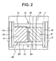
Fig. 2 is a cross-sectional diagram obtained by taking along a line II-II ofFig. 1 ; -
Fig. 3 is a side view showing a state where the rotating handrails ofFig. 1 have rotated to an open position; -
Fig. 4 is a cross-sectional diagram obtained by taking along a line IV-IV ofFig. 3 ; -
Fig. 5 is a side view showing a car-top handrail unit for an elevator according toEmbodiment 2 of the present invention; -
Fig. 6 is a cross-sectional diagram obtained by taking along a line VI-VI ofFig. 5 ; -
Fig. 7 is a plan view showing the main portion of a car-top handrail unit for an elevator according to Embodiment 3 of the present invention; -
Fig. 8 is a plan view showing the main portions of a car-top handrail unit for an elevator according to Embodiment 4 of the present invention; -
Fig. 9 is a plan view showing the main portion of a car-top handrail unit for an elevator according to Embodiment 5 of the present invention; -
Fig. 10 is a perspective view showing an example of a conventional car-top handrail unit for an elevator; -
Fig. 11 is a side view showing the car-top handrail unit inFig. 10 ; and -
Fig. 12 is a side view showing a state where the car-top handrail unit inFig. 11 is folded away. - Hereinafter, description will be made of preferred embodiments of the present invention with reference to drawings.
-
Fig. 1 is a side view showing a car-top handrail unit for an elevator according to Embodiment 1 of the present invention andFig. 2 is a cross-sectional diagram obtained by taking along a line II-II ofFig. 1 . In the figures, a pair ofguide rails 12 is provided within a hoistway 11. Acar 13 ascends/descends within the hoistway 11 while being guided by theguide rails 12.Doors car 13. - On a landing side, there are provided
doors doors beam 18 of the building, used for lifting devices at the time of installation of the elevator, is installed upward of thecar 13 within the hoistway 11. - A car-
top handrail unit 20, which surrounds working areas A and B for performing maintenance and inspection work on thecar 13, is provided on thecar 13. The car-top handrail unit 20 has a pair of fixedhandrails handrails - The
fixed handrails car 13 being spaced apart from each other in the width direction of the car 13 (upper and lower direction inFig. 2 ). Further, one end portion of each of thefixed handrails car 13. The other end portions of thefixed handrails Fig. 2 ). - The rotating
handrails car 13 from the other end portions of the pair offixed handrails car 13 from the other end portions of the pair offixed handrails Fig. 3 andFig. 4 (a double door type). - In such a car-
top handrail unit 20, a member of maintenance personnel steps onto thecar 13 from the landing on the front side of the car 13 (left side inFig. 1 andFig. 2 ). When the rotatinghandrails Fig. 3 andFig. 4 , therotating handrails car 13 has descended to a position at which the rotatinghandrails beam 18. - During normal operation, as shown in
Fig. 1 , therotating handrails beam 18 or device(s) positioned upward of thecar 13, as therotating handrails - That is, it is possible to avoid interference of the car-
top handrail unit 20 with thebeam 18 or device(s) positioned upward of thecar 13. Further, by simply rotating the rotatinghandrails top handrail unit 20 with thebeam 18 or any device(s) can be avoided at the same time, thus cost can be decreased with a simple structure, and also avoiding any undue increase in the time taken to carry out the maintenance work. - Furthermore, while the
beam 18 for lifting, used when installing the elevator, can be removed after installation, this requires time and labor. In contrast to this, according to the structure of Embodiment 1, the car-top handrail unit 20 does not interfere with thebeam 18, meaning thebeam 18 can be retained, and it becomes possible to eliminate the time and labor necessary for the removal of the beam. - Moreover, by retaining the
beam 18, thecar 13 can be suspended from thebeam 18 at the time of exchanging the main rope (not shown) for suspending thecar 13. Therefore, the time and labor involved in providing a new lifting member can be eliminated, enhancing the workability of maintenance work. - Next,
Fig. 5 is a side view showing a car-top handrail unit for an elevator according toEmbodiment 2 of the present invention andFig. 6 is a cross-sectional diagram obtained by taking along a line VI-VI ofFig. 5 . InEmbodiment 2, thedoor 14 of the car is provided only on the front side of thecar 13. Arear handrail 25 is mounted in a rear end portion on thecar 13 so as to connect the rotatinghandrails - As described above, in the case where there is no door on the rear side of the
car 13, arear handrail 25 needs to be mounted on the rear end portion on thecar 13. In this case, therear handrail 25 is fixed to a position where therear handrail 25 will not interfere with abeam 18 or device(s) inside the hoistway at the time of normal operation, and the rotatinghandrails rear handrail 25 when the rotatinghandrails beam 18 or device(s) positioned upward of thecar 13 and to decrease cost with a simple structure, as well as avoiding any undue increase in time to carry out maintenance work. - Next,
Fig. 7 is a plan view showing the main portions of a car-top handrail unit for an elevator according to Embodiment 3 of the present invention. In this example, provided on both end portions of arear handrail 25 arestoppers rotating handrails rotating handrails Embodiment 2. - In such a car-top handrail unit, the rotation of the
rotating handrails rotating handrails - Next,
Fig. 8 is a plan view showing the main portions of a car-top handrail unit for an elevator according to Embodiment 4 of the present invention. In the figure,rotating handrails set screw 28 serving as retaining means for connecting them with each other. Further, the direction of rotation of therotating handrails - In such a car-top handrail unit, the
rotating handrails set screw 28. Thus, therotating handrails rotating handrails beam 18 or device(s) positioned upward ofcar 13 can be prevented more securely. - Further, the
rotating handrails rotating handrails set screw 28, and thereby workability is enhanced. - Note that the retaining means is not limited to the
set screw 28 and may be, for example, an engaging member such as a hook, which is hung between therotating handrails rotating handrails rotating handrails - Next,
Fig. 9 is a plan view showing the main portions of a car-top handrail unit for an elevator according to Embodiment 5 of the present invention. In the figure, arranged betweenrotating handrails micro switch 31 serving as a detecting means for detecting whether therotating handrails micro switch 31 is mounted on the one rotatinghandrail 23 and is operated by the otherrotating handrail 24. - A detection signal from the
micro switch 31 is outputted to a control device (not shown) for controlling operation of the elevator. With the use of this control device, normal operation can be performed when the rotatinghandrail 24 is in the closed position. However, when the rotatinghandrail 24 is not in the closed position, it is regarded that there is a danger of interference of the car-top handrail unit withbeam 18 or the like, and thus the range in which thecar 13 can ascend is limited. - In such a car-top handrail unit, because of the provision of the
micro switch 31, therotating handrails beam 18, or device(s) and the like positioned upward thecar 13. - Note that the detecting means is not limited to the
micro switch 31, and it is possible to use other mechanical switches, optical switches, proximity sensors or the like.
Claims (6)
- A car-top handrail unit for an elevator, which is provided on a car and surrounds a working area for performing maintenance and inspection work on the car (13), comprising:a pair of fixed handrails (21, 22) provided uprightly on the upper portion of the car (13) being spaced apart from each other in the width direction of the car (13), each having one end portion positioned in the vicinity of the front end portion of the car (13) and the other end portion positioned in a middle portion in the depth direction of the car (13); anda pair of rotating handrails (23, 24) each being capable of rotating between a closed position, in which the rotating handrails (23, 24) extend along the width direction of the car (13) from the other end portions of the pair of fixed handrails (21, 22) and closes the gap between the other end portions and as such defining a working area with surface area (A), and an open position, in which the rotating handrails (23, 24) extend along the depth direction of the car (13) from the other end portions of the pair of fixed handrails (21, 22) and as such enlarging the surface area (A+B) of the working area.
- The car-top handrail unit for an elevator according to claim 1, further comprising a rear handrail (25) disposed in the rear end portion of the car (13) so as to make connection between end portions of the rotating handrails (23, 24) when they are in the open position.
- The car-top handrail unit for an elevator according to claim 2, wherein stoppers (26, 27) are provided on the rear handrail (25), in which the rotating handrails (23, 24) are brought into contact with each other in the tip end portions for regulating rotation of the rotating handrails (23, 24).
- The car-top handrail unit for an elevator according to claim 1, further comprising a retaining means (28) for keeping the rotating handrails (23, 24) in the closed position by connecting the pair of rotating handrails (23, 24) to each other.
- The car-top handrail unit for an elevator according to claim 4, further comprising a biasing means (29, 30) for biasing the direction of rotation of the rotating handrails (23, 24) in the open position.
- The car-top handrail unit for an elevator according to claim 1, further comprising a detecting means (31) for detecting whether the rotating handrails (23, 24) are in the closed position and for outputting a detection signal to a control device that controls the operation of the elevator.
Applications Claiming Priority (1)
| Application Number | Priority Date | Filing Date | Title |
|---|---|---|---|
| PCT/JP2000/009425 WO2002053484A1 (en) | 2000-12-28 | 2000-12-28 | Car upper handrail device of elevator |
Publications (3)
| Publication Number | Publication Date |
|---|---|
| EP1346942A1 EP1346942A1 (en) | 2003-09-24 |
| EP1346942A4 EP1346942A4 (en) | 2006-04-26 |
| EP1346942B1 true EP1346942B1 (en) | 2008-08-27 |
Family
ID=11736870
Family Applications (1)
| Application Number | Title | Priority Date | Filing Date |
|---|---|---|---|
| EP00985997A Expired - Lifetime EP1346942B1 (en) | 2000-12-28 | 2000-12-28 | Car upper handrail device of elevator |
Country Status (5)
| Country | Link |
|---|---|
| EP (1) | EP1346942B1 (en) |
| JP (1) | JP4694096B2 (en) |
| CN (1) | CN1289377C (en) |
| DE (1) | DE60040100D1 (en) |
| WO (1) | WO2002053484A1 (en) |
Families Citing this family (9)
| Publication number | Priority date | Publication date | Assignee | Title |
|---|---|---|---|---|
| JP4839566B2 (en) * | 2001-04-17 | 2011-12-21 | 三菱電機株式会社 | Elevator cage and elevator device |
| JPWO2005073120A1 (en) * | 2004-01-30 | 2007-08-23 | 三菱電機株式会社 | Elevator equipment |
| JP4619016B2 (en) * | 2004-03-01 | 2011-01-26 | 東芝エレベータ株式会社 | View elevator equipment platform |
| NL1030867C2 (en) * | 2006-01-06 | 2007-07-09 | Melker B V De | Safety construction is for lift and comprises at least two uprights, at least one horizontal piece connected with uprights, devices for fixture of construction to lift cage, at least one bolting component for securing the construction |
| JP4415025B2 (en) * | 2007-02-28 | 2010-02-17 | 株式会社日立ビルシステム | Elevator car handrail device |
| MY184216A (en) * | 2015-01-20 | 2021-03-26 | Inventio Ag | Elevator |
| JP6429742B2 (en) * | 2015-07-06 | 2018-11-28 | 三菱電機株式会社 | Elevator car equipment |
| JP6366847B2 (en) * | 2015-07-23 | 2018-08-01 | 三菱電機株式会社 | Elevator car handrail device |
| WO2018078211A1 (en) * | 2016-10-25 | 2018-05-03 | Kone Corporation | Elevator and elevator car roof railing |
Family Cites Families (3)
| Publication number | Priority date | Publication date | Assignee | Title |
|---|---|---|---|---|
| JPH0242704Y2 (en) * | 1986-04-30 | 1990-11-14 | ||
| JPH04292386A (en) * | 1991-03-20 | 1992-10-16 | Toshiba Corp | Safety fence for hydraulic elevator cage |
| JP4245209B2 (en) * | 1998-09-03 | 2009-03-25 | 東芝エレベータ株式会社 | Elevator |
-
2000
- 2000-12-28 CN CN00819195.6A patent/CN1289377C/en not_active Expired - Fee Related
- 2000-12-28 EP EP00985997A patent/EP1346942B1/en not_active Expired - Lifetime
- 2000-12-28 WO PCT/JP2000/009425 patent/WO2002053484A1/en active IP Right Grant
- 2000-12-28 DE DE60040100T patent/DE60040100D1/en not_active Expired - Lifetime
- 2000-12-28 JP JP2002554610A patent/JP4694096B2/en not_active Expired - Fee Related
Also Published As
| Publication number | Publication date |
|---|---|
| DE60040100D1 (en) | 2008-10-09 |
| EP1346942A1 (en) | 2003-09-24 |
| JPWO2002053484A1 (en) | 2004-04-30 |
| JP4694096B2 (en) | 2011-06-01 |
| CN1289377C (en) | 2006-12-13 |
| WO2002053484A1 (en) | 2002-07-11 |
| EP1346942A4 (en) | 2006-04-26 |
| CN1437556A (en) | 2003-08-20 |
Similar Documents
| Publication | Publication Date | Title |
|---|---|---|
| JP4191331B2 (en) | Elevator equipment | |
| EP1346942B1 (en) | Car upper handrail device of elevator | |
| JP4255523B2 (en) | Elevator | |
| EP1013593B1 (en) | Control device for elevator | |
| EP1396457B1 (en) | Elevator device | |
| JPWO2003020628A1 (en) | Elevator equipment | |
| EP1195346B1 (en) | Elevator device | |
| EP2108610B1 (en) | Machine-room-less elevator | |
| EP1020393B1 (en) | Elevator | |
| KR20010094686A (en) | Installation structure and installation method for winch of machine-roomless elevator | |
| JP6580528B2 (en) | Hoisting machine installation method and elevator | |
| EP1057769B1 (en) | Elevator | |
| EP1329411B1 (en) | Elevator device | |
| JP4142009B2 (en) | Elevator equipment | |
| JPS63202579A (en) | Method of renewal construction of elevator | |
| EP2636627A1 (en) | Elevator | |
| EP2135833B1 (en) | Elevator system | |
| EP1329410B1 (en) | Elevator and car position confirmation device for the elevator | |
| KR100420027B1 (en) | Link structure for elevator governor | |
| JP4566623B2 (en) | Movable landing equipment for elevators for base-isolated buildings | |
| JP2006240786A (en) | Hall device for elevator of base isolated building | |
| JP2002087732A (en) | Elevator device | |
| EP1493706B1 (en) | Elevator device | |
| JP4752268B2 (en) | Elevator equipment | |
| JP4249503B2 (en) | Machine room-less elevator hoist maintenance method |
Legal Events
| Date | Code | Title | Description |
|---|---|---|---|
| PUAI | Public reference made under article 153(3) epc to a published international application that has entered the european phase |
Free format text: ORIGINAL CODE: 0009012 |
|
| 17P | Request for examination filed |
Effective date: 20020918 |
|
| AK | Designated contracting states |
Kind code of ref document: A1 Designated state(s): AT BE CH CY DE DK ES FI FR GB GR IE IT LI LU MC NL PT SE TR |
|
| RBV | Designated contracting states (corrected) |
Designated state(s): DE FR NL |
|
| A4 | Supplementary search report drawn up and despatched |
Effective date: 20060313 |
|
| RAP1 | Party data changed (applicant data changed or rights of an application transferred) |
Owner name: MITSUBISHI DENKI KABUSHIKI KAISHA |
|
| 17Q | First examination report despatched |
Effective date: 20061116 |
|
| 17Q | First examination report despatched |
Effective date: 20061116 |
|
| GRAP | Despatch of communication of intention to grant a patent |
Free format text: ORIGINAL CODE: EPIDOSNIGR1 |
|
| GRAS | Grant fee paid |
Free format text: ORIGINAL CODE: EPIDOSNIGR3 |
|
| GRAA | (expected) grant |
Free format text: ORIGINAL CODE: 0009210 |
|
| AK | Designated contracting states |
Kind code of ref document: B1 Designated state(s): DE FR NL |
|
| REF | Corresponds to: |
Ref document number: 60040100 Country of ref document: DE Date of ref document: 20081009 Kind code of ref document: P |
|
| PLBE | No opposition filed within time limit |
Free format text: ORIGINAL CODE: 0009261 |
|
| STAA | Information on the status of an ep patent application or granted ep patent |
Free format text: STATUS: NO OPPOSITION FILED WITHIN TIME LIMIT |
|
| 26N | No opposition filed |
Effective date: 20090528 |
|
| PGFP | Annual fee paid to national office [announced via postgrant information from national office to epo] |
Ref country code: FR Payment date: 20101224 Year of fee payment: 11 |
|
| PGFP | Annual fee paid to national office [announced via postgrant information from national office to epo] |
Ref country code: NL Payment date: 20101220 Year of fee payment: 11 |
|
| REG | Reference to a national code |
Ref country code: NL Ref legal event code: V1 Effective date: 20120701 |
|
| REG | Reference to a national code |
Ref country code: FR Ref legal event code: ST Effective date: 20120831 |
|
| PG25 | Lapsed in a contracting state [announced via postgrant information from national office to epo] |
Ref country code: NL Free format text: LAPSE BECAUSE OF NON-PAYMENT OF DUE FEES Effective date: 20120701 |
|
| PG25 | Lapsed in a contracting state [announced via postgrant information from national office to epo] |
Ref country code: FR Free format text: LAPSE BECAUSE OF NON-PAYMENT OF DUE FEES Effective date: 20120102 |
|
| REG | Reference to a national code |
Ref country code: DE Ref legal event code: R084 Ref document number: 60040100 Country of ref document: DE |
|
| PGFP | Annual fee paid to national office [announced via postgrant information from national office to epo] |
Ref country code: DE Payment date: 20171220 Year of fee payment: 18 |
|
| REG | Reference to a national code |
Ref country code: DE Ref legal event code: R119 Ref document number: 60040100 Country of ref document: DE |
|
| PG25 | Lapsed in a contracting state [announced via postgrant information from national office to epo] |
Ref country code: DE Free format text: LAPSE BECAUSE OF NON-PAYMENT OF DUE FEES Effective date: 20190702 |