EP1346861A1 - Seitenaufprallträger - Google Patents
Seitenaufprallträger Download PDFInfo
- Publication number
- EP1346861A1 EP1346861A1 EP02013278A EP02013278A EP1346861A1 EP 1346861 A1 EP1346861 A1 EP 1346861A1 EP 02013278 A EP02013278 A EP 02013278A EP 02013278 A EP02013278 A EP 02013278A EP 1346861 A1 EP1346861 A1 EP 1346861A1
- Authority
- EP
- European Patent Office
- Prior art keywords
- longitudinal
- bead
- side impact
- beads
- transverse
- Prior art date
- Legal status (The legal status is an assumption and is not a legal conclusion. Google has not performed a legal analysis and makes no representation as to the accuracy of the status listed.)
- Granted
Links
Images
Classifications
-
- B—PERFORMING OPERATIONS; TRANSPORTING
- B60—VEHICLES IN GENERAL
- B60J—WINDOWS, WINDSCREENS, NON-FIXED ROOFS, DOORS, OR SIMILAR DEVICES FOR VEHICLES; REMOVABLE EXTERNAL PROTECTIVE COVERINGS SPECIALLY ADAPTED FOR VEHICLES
- B60J5/00—Doors
- B60J5/04—Doors arranged at the vehicle sides
- B60J5/042—Reinforcement elements
- B60J5/0422—Elongated type elements, e.g. beams, cables, belts or wires
- B60J5/0438—Elongated type elements, e.g. beams, cables, belts or wires characterised by the type of elongated elements
- B60J5/0443—Beams
- B60J5/0444—Beams characterised by a special cross section
Definitions
- the invention relates to a side impact beam for incorporation into a motor vehicle, which consists of a profiled metal sheet with at least one Longitudinal bead and widened end sections.
- DE 296 22 985 U1 includes a side impact beam as part of the prior art with a flat end section on which a bent connection lug is provided. This forms a hook and protrudes when closed Door into one of the door pillars of the vehicle body.
- the hook in addition to the door lock connection of the vehicle door, a second positive Establish connection and in the event of a side impact for one provide additional security.
- a side impact beam is part of the prior art Technology with a profiled side member and lateral flat and widened End portions.
- the end sections over which the connection in the motor vehicle is made to be consistently flat. Therefore subject to The profile ends meet the highest flatness requirements to keep them within series production in the vehicle structure.
- the object of the invention is therefore based on the prior art to create a functionally improved side impact beam with flat end sections suitable for installation, for a large series production a high degree of reproducibility is ensured.
- this object is achieved in a side impact beam according to the features of claim 1.
- At least one is transverse to Longitudinal bead of the side impact beam aligned cross bead provided.
- This additional cross bead in the end sections ensures that the connection surfaces in the end sections are flat.
- the geometry of the cross beads in terms of their dimensions and shape is on the respective side impact beams and their installation or installation situation Voted.
- the side impact beam according to the invention is thus dimensionally optimized profile components. Installation problems due to dimensional inaccuracies the connection areas are significantly reduced or even complete locked out.
- the stiffening of the profile ends also supports the function of the side impact beam and improves the crash behavior.
- the Manufacturing method is simple and the cost of this is low.
- the length of a transverse bead preferably corresponds to the width of a longitudinal bead.
- a side impact beam is considered to be particularly efficient, in which two longitudinal beads are arranged side by side. In both End sections each have a transverse bead, the length of which is approximately Corresponds to the width of the two longitudinal beads.
- the longitudinal beads and the transverse beads in are not mandatory, but are advantageous the same direction, with the cross beads immediately in front of the in the End sections outgoing longitudinal beads are.
- the side impact beam according to the invention is preferably manufactured from a metal sheet made of high-strength steel with a tensile strength of 1000 N / mm 2 or higher, namely by cold working.
- the transverse bead In practical tests, there have been geometric dimensions of the transverse bead found to be advantageous, in which the depth is approximately 4 mm and the width is about 6 mm.
- the length of a cross bead extends over approx. 2/3 of the Width of an end section.
- transverse beads are expediently perpendicular to the longitudinal bead or beads aligned. Basically, it is also possible to cover the cross beads on the longitudinal axis of the side impact beam or the longitudinal bead, to be arranged at an angle, i.e. at an angle.
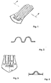
- Figures 1 and 3 show an end region of a side impact beam 1 for incorporation into a vehicle door, not shown here Motor vehicle.
- the side impact beam 1 consists of a cold-formed profiled metal sheet 2 with a thickness between 1.0 mm and 3.0 mm. He should brace the vehicle door in the event of a side impact and under homogeneous deformation Absorb energy.
- the side impact beam 1 has two over most of its length longitudinal beads 3, 4 extending alongside one another.
- the longitudinal beads 3, 4 are semi-tubular or curved in a hat shape and connected via a common central web 5.
- On both outer longitudinal sides 6, 7 of the metal profile 2 are transversely projecting Longitudinal webs 8, 9 are provided.
- the metal profile 2 has a widened end section 10 at each end on. With the end sections 10, the side impact beam 1 becomes in the vehicle structure established. It can be seen in FIG. 1 as well as in the illustration 3 two openings 11, 12 for carrying out fasteners. Usually the side impact beam 1 over the end portions 10 welded in the door frame of the body.
- the height of the longitudinal beads 3, 4 decreases towards the end sections 10 and expires in their level.
- In front of the ends 13, 14 of the longitudinal beads 3, 4 is one Cross bead 15 introduced.
- Figure 4 shows the transverse bead 15 in cross section.
- transverse bead 15 and the longitudinal beads 3, 4 are pronounced in the same direction, the length L 15 of the transverse bead 15 corresponding approximately to the width B 3.4 of the two longitudinal beads 3, 4.
- the transverse bead 15 is used in the manufacture of the side impact beam 1 after Forming the longitudinal beads 2, 3 in a downstream forming process in introduced a further tool level.
- the connection surfaces 16 of the end sections 10 are leveled or directed and calibrated. Any deformations from the upstream forming process are straightened.
- the end sections 10 are stiffened, whereby the crash behavior of the side impact beam 1 can be improved can.
Landscapes
- Engineering & Computer Science (AREA)
- Mechanical Engineering (AREA)
- Body Structure For Vehicles (AREA)
- Vibration Dampers (AREA)
Abstract
Description
- Figur 1
- in perspektivischer Darstellungsweise ein Ende eines Seitenaufprallträgers;
- Figur 2
- einen vertikalen Querschnitt durch die Darstellung gemäß der Figur 1 entlang der Linie A-A;
- Figur 3
- den Endabschnitt des Seitenaufprallträgers in der Draufsicht und
- Figur 4
- einen Schnitt durch die Darstellung der Figur 3 entlang der Linie B-B.
- 1 -
- Seitenaufprallträger
- 2 -
- Metallblech
- 3 -
- Längssicke
- 4 -
- Längssicke
- 5 -
- Mittelsteg
- 6 -
- Längssicke
- 7 -
- Längssicke
- 8 -
- Längssteg
- 9 -
- Längssteg
- 10-
- Endabschnitt
- 11 -
- Öffnung
- 12 -
- Öffnung
- 13 -
- Ende v. 2
- 14 -
- Ende v. 3
- 15 -
- Quersicke
- 16 -
- Anbindungsfläche
- B3,4 -
- Breite v. 3, 4
- L15 -
- Länge v. 15
Claims (5)
- Seitenaufprallträger zur Eingliederung in ein Kraftfahrzeug, welcher aus einem profilierten Metallblech mit mindestens einer Längssicke (3, 4) und verbreiterten Endabschnitten (10) besteht, dadurch gekennzeichnet, dass in den Endabschnitten (10) quer zur Längssicke (3, 4) ausgerichtete Quersicken (15) ausgebildet sind.
- Seitenaufprallträger nach Patentanspruch 1, dadurch gekennzeichnet, dass die Länge einer Quersicke (15) der Breite einer Längssicke (3 bzw. 4) entspricht.
- Seitenaufprallträger nach Patentanspruch 1 oder 2, dadurch gekennzeichnet, dass zwei sich nebeneinander erstreckende Längssicken (3, 4) vorgesehen sind und die Länge (L15) jeder Quersicke (15) etwa der Breite (B3,4) der beiden Längssicken (3, 4) entspricht.
- Seitenaufprallträger nach einem der Patentansprüche 1 bis 3, dadurch gekennzeichnet, dass jede Längssicke (3, 4) und die Quersicken (15) in dieselbe Richtung ausgeprägt sind.
- Seitenaufprallträger nach einem der Patentansprüche 1 bis 4, dadurch gekennzeichnet, dass die Quersicken (15) unmittelbar vor den Enden (13, 14) jeder Längssicke (3, 4) liegen.
Applications Claiming Priority (2)
| Application Number | Priority Date | Filing Date | Title |
|---|---|---|---|
| DE10212792A DE10212792B4 (de) | 2002-03-22 | 2002-03-22 | Seitenaufprallträger |
| DE10212792 | 2002-03-22 |
Publications (2)
| Publication Number | Publication Date |
|---|---|
| EP1346861A1 true EP1346861A1 (de) | 2003-09-24 |
| EP1346861B1 EP1346861B1 (de) | 2004-08-11 |
Family
ID=27771494
Family Applications (1)
| Application Number | Title | Priority Date | Filing Date |
|---|---|---|---|
| EP02013278A Expired - Lifetime EP1346861B1 (de) | 2002-03-22 | 2002-07-01 | Seitenaufprallträger |
Country Status (4)
| Country | Link |
|---|---|
| US (1) | US7086686B2 (de) |
| EP (1) | EP1346861B1 (de) |
| AT (1) | ATE273147T1 (de) |
| DE (2) | DE10212792B4 (de) |
Families Citing this family (25)
| Publication number | Priority date | Publication date | Assignee | Title |
|---|---|---|---|---|
| DE10256137B3 (de) * | 2002-11-29 | 2004-01-22 | Benteler Automobiltechnik Gmbh | Seitenaufprallträger |
| US7664080B2 (en) * | 2004-10-27 | 2010-02-16 | Honeywell International Inc. | Discreet event operators for event management in a wireless sensor network |
| US7561544B2 (en) * | 2004-10-27 | 2009-07-14 | Honeywell International Inc. | Machine architecture for event management in a wireless sensor network |
| US7630336B2 (en) * | 2004-10-27 | 2009-12-08 | Honeywell International Inc. | Event-based formalism for data management in a wireless sensor network |
| US8027280B2 (en) * | 2004-10-27 | 2011-09-27 | Honeywell International Inc. | Layered architecture for data management in a wireless sensor network |
| US7590098B2 (en) * | 2004-10-27 | 2009-09-15 | Honeywell International Inc. | Publish/subscribe model in a wireless sensor network |
| US7715308B2 (en) * | 2004-12-09 | 2010-05-11 | Honeywell International Inc. | Fault tolerance in a wireless network |
| DE102005014570B4 (de) * | 2005-03-31 | 2016-07-07 | Man Truck & Bus Ag | Fahrzeugtür für ein Nutzfahrzeug |
| SE530404C2 (sv) * | 2006-09-11 | 2008-05-27 | Gestamp Hardtech Ab | Fordonsdörr och krockskyddsbalk till sådan |
| JP5303211B2 (ja) * | 2008-04-08 | 2013-10-02 | 本田技研工業株式会社 | 車両用ドア構造体およびその製造方法 |
| DE102009002777B4 (de) * | 2009-04-30 | 2014-11-20 | Faurecia Innenraum Systeme Gmbh | Versteifungsstrebe |
| DE102010023325A1 (de) * | 2010-06-10 | 2011-12-15 | Benteler Automobiltechnik Gmbh | Türaufprallträger |
| US8833832B2 (en) * | 2011-08-16 | 2014-09-16 | Ford Global Technologies, Llc | Node for connecting vehicle body portions |
| DE112013003629T5 (de) * | 2012-07-23 | 2015-05-07 | Magna International Inc. | Fahrzeugtür |
| DE102013200073B4 (de) * | 2012-09-03 | 2026-03-19 | Magna International Inc. | Stoßfängerträger |
| DE102012215598B4 (de) * | 2012-09-03 | 2019-02-14 | Magna International Inc. | Aufprallträger |
| SE536735C2 (sv) * | 2012-11-29 | 2014-07-01 | Gestamp Hardtech Ab | Dörrbalk för fordon |
| US10041517B2 (en) * | 2013-01-24 | 2018-08-07 | Aktiebolaget Skf | Fastener element |
| WO2014162900A1 (ja) * | 2013-04-03 | 2014-10-09 | 本田技研工業株式会社 | 車両用ドア |
| CN107618569A (zh) * | 2016-07-15 | 2018-01-23 | 天津瑞林迪金属制品有限公司 | 前防撞梁立柱本体 |
| KR101896325B1 (ko) | 2016-11-15 | 2018-09-07 | 현대자동차 주식회사 | 차량용 cfrp 도어의 임팩트 빔 구조 |
| KR20200001257A (ko) * | 2018-06-27 | 2020-01-06 | 현대자동차주식회사 | 도어 임팩트 빔 |
| CN114728322B (zh) * | 2019-09-25 | 2024-07-12 | 日本制铁株式会社 | 构造构件、构造构件制造方法及构造构件制造装置 |
| DE102022125461A1 (de) | 2022-10-04 | 2024-04-04 | Bayerische Motoren Werke Aktiengesellschaft | Seitenaufprallträger für eine Kraftfahrzeugtür, Herstellverfahren und Kraftfahrzeugtür mit einem solchen Seitenaufprallträger |
| DE102024202730A1 (de) * | 2024-03-21 | 2025-09-25 | Volkswagen Aktiengesellschaft | Türaufprallträger, Tür und Kraftfahrzeug |
Citations (3)
| Publication number | Priority date | Publication date | Assignee | Title |
|---|---|---|---|---|
| JPH04238727A (ja) * | 1991-01-14 | 1992-08-26 | Toyota Motor Corp | 自動車ドア用インパクトビーム |
| DE4328441A1 (de) * | 1993-08-24 | 1995-03-02 | Linde & Wiemann Gmbh Kg | Seitenaufprallschutz in Form eines an der Tür eines Kraftfahrzeuges befestigbaren Profilgliedes sowie Verfahren zur Herstellung des Profilgliedes |
| US5580120A (en) * | 1995-02-23 | 1996-12-03 | Mascotech Tubular Products, Inc. | Vehicle door intrusion beam |
Family Cites Families (10)
| Publication number | Priority date | Publication date | Assignee | Title |
|---|---|---|---|---|
| JPS5639698Y2 (de) * | 1975-10-01 | 1981-09-16 | ||
| US5404690A (en) * | 1993-03-26 | 1995-04-11 | Crescive Die & Tool, Inc. | Impact beam assembly method and apparatus |
| US5370437A (en) * | 1993-08-19 | 1994-12-06 | Benteler Industries, Inc. | Universal impact beam tube pocket |
| JP3763858B2 (ja) * | 1995-02-14 | 2006-04-05 | ユニプレス株式会社 | 自動車用ドアのガードビーム |
| US6482496B1 (en) * | 1996-07-03 | 2002-11-19 | Henkel Corporation | Foil backed laminate reinforcement |
| DE19647334B4 (de) * | 1996-11-15 | 2004-07-15 | Benteler Ag | Seitenaufprallträger für einen Personenkraftwagen |
| DE29622985U1 (de) * | 1996-12-24 | 1997-10-02 | Thyssen Industrie Ag, 45128 Essen | Seitenaufprallschutz für Kfz-Türen |
| BR9913772A (pt) | 1998-09-16 | 2001-06-05 | Cosma Int Inc | Viga de reforço de porta de veìculo e processo para fabricar a mesma |
| US6454884B1 (en) * | 2000-06-12 | 2002-09-24 | Pullman Industries, Inc. | Method of manufacturing a vehicle structural beam |
| WO2002004240A1 (en) * | 2000-07-12 | 2002-01-17 | Shape Corporation | Roll-formed and stamped doorbeam |
-
2002
- 2002-03-22 DE DE10212792A patent/DE10212792B4/de not_active Expired - Fee Related
- 2002-07-01 EP EP02013278A patent/EP1346861B1/de not_active Expired - Lifetime
- 2002-07-01 AT AT02013278T patent/ATE273147T1/de not_active IP Right Cessation
- 2002-07-01 DE DE50200804T patent/DE50200804D1/de not_active Expired - Lifetime
- 2002-10-29 US US10/282,546 patent/US7086686B2/en not_active Expired - Fee Related
Patent Citations (3)
| Publication number | Priority date | Publication date | Assignee | Title |
|---|---|---|---|---|
| JPH04238727A (ja) * | 1991-01-14 | 1992-08-26 | Toyota Motor Corp | 自動車ドア用インパクトビーム |
| DE4328441A1 (de) * | 1993-08-24 | 1995-03-02 | Linde & Wiemann Gmbh Kg | Seitenaufprallschutz in Form eines an der Tür eines Kraftfahrzeuges befestigbaren Profilgliedes sowie Verfahren zur Herstellung des Profilgliedes |
| US5580120A (en) * | 1995-02-23 | 1996-12-03 | Mascotech Tubular Products, Inc. | Vehicle door intrusion beam |
Non-Patent Citations (1)
| Title |
|---|
| PATENT ABSTRACTS OF JAPAN vol. 017, no. 008 (M - 1350) 7 January 1993 (1993-01-07) * |
Also Published As
| Publication number | Publication date |
|---|---|
| DE10212792A1 (de) | 2003-10-16 |
| DE50200804D1 (de) | 2004-09-16 |
| US20030178273A1 (en) | 2003-09-25 |
| EP1346861B1 (de) | 2004-08-11 |
| US7086686B2 (en) | 2006-08-08 |
| DE10212792B4 (de) | 2005-05-12 |
| ATE273147T1 (de) | 2004-08-15 |
Similar Documents
| Publication | Publication Date | Title |
|---|---|---|
| EP1346861B1 (de) | Seitenaufprallträger | |
| DE102004056956B4 (de) | Konstruktion für eine Stoßstangenverstärkung | |
| DE102018119735B4 (de) | Stoßfängerquerträger für ein Kraftfahrzeug | |
| EP1479842B1 (de) | Hohlprofil | |
| DE102013114690B4 (de) | Außenpaneel für eine Fahrzeugsäule | |
| CH658285A5 (de) | Stegrost und verfahren zu dessen herstellung. | |
| DE3707554A1 (de) | Tragschiene fuer einen fahrzeugrahmen und fahrzeugunterbau | |
| DE10006348C2 (de) | Bauteil mit lokal begrenzten Versteifungsbereichen und Verfahren zu seiner Herstellung | |
| DE19882454B4 (de) | Tragsäule für eine Fahrzeugkarosserie | |
| DE102011112256A1 (de) | Kraftfahrzeug mit Crashbox | |
| DE102008023340A1 (de) | Aggregateträger für ein Getriebe eines Kraftfahrzeugs | |
| DE2614691C3 (de) | Gleiskette | |
| DE202014103276U1 (de) | Kurze Versatz-Blechverstärkung zur Begrenzung der Rotation während eines Unfalls | |
| DE3001309C2 (de) | ||
| EP1307670A1 (de) | Kette, kettenrad und kettentrieb für ein hebezeug | |
| EP1424233B1 (de) | Seitenaufprallträger | |
| DE4327393A1 (de) | Seitenaufprallschutz in Form eines an der Tür eines Kraftfahrzeuges befestigbaren Profilgliedes sowie Verfahren zur Herstellung des Profilgliedes | |
| DE102005017981B4 (de) | Säule einer Karosserie eines Kraftfahrzeugs | |
| DE19645517A1 (de) | Türblatt, insbesondere für Aufzugstüren | |
| DE10249117B4 (de) | Aus Blechpressteilen bestehende Mittelsäule, einer Kraftfahrzeugkarosserie | |
| DE102004025857A1 (de) | Rohrprofil mit bereichsweise gekrümmtem Verlauf und Verfahren zu seiner Herstellung | |
| DE102022126492A1 (de) | Verfahren zur herstellung eines karosseriestrukturbauteils mit verstärkten bereichen | |
| DE19837083A1 (de) | Karosseriebauteil für die Karosserie eines Kraftfahrzeugs | |
| DE10138034A1 (de) | Seitenaufprallträger | |
| EP0738361B1 (de) | Kaltgewalzter betonstahl und verfahren zu dessen herstellung |
Legal Events
| Date | Code | Title | Description |
|---|---|---|---|
| PUAI | Public reference made under article 153(3) epc to a published international application that has entered the european phase |
Free format text: ORIGINAL CODE: 0009012 |
|
| 17P | Request for examination filed |
Effective date: 20030704 |
|
| AK | Designated contracting states |
Kind code of ref document: A1 Designated state(s): AT BE BG CH CY CZ DE DK EE ES FI FR GB GR IE IT LI LU MC NL PT SE SK TR |
|
| AX | Request for extension of the european patent |
Extension state: AL LT LV MK RO SI |
|
| 17Q | First examination report despatched |
Effective date: 20031124 |
|
| GRAP | Despatch of communication of intention to grant a patent |
Free format text: ORIGINAL CODE: EPIDOSNIGR1 |
|
| GRAS | Grant fee paid |
Free format text: ORIGINAL CODE: EPIDOSNIGR3 |
|
| AKX | Designation fees paid |
Designated state(s): AT BE BG CH CY CZ DE DK EE ES FI FR GB GR IE IT LI LU MC NL PT SE SK TR |
|
| GRAA | (expected) grant |
Free format text: ORIGINAL CODE: 0009210 |
|
| RAP1 | Party data changed (applicant data changed or rights of an application transferred) |
Owner name: BENTELER AUTOMOBILTECHNIK GMBH |
|
| AK | Designated contracting states |
Kind code of ref document: B1 Designated state(s): AT BE BG CH CY CZ DE DK EE ES FI FR GB GR IE IT LI LU MC NL PT SE SK TR |
|
| PG25 | Lapsed in a contracting state [announced via postgrant information from national office to epo] |
Ref country code: IT Free format text: LAPSE BECAUSE OF FAILURE TO SUBMIT A TRANSLATION OF THE DESCRIPTION OR TO PAY THE FEE WITHIN THE PRESCRIBED TIME-LIMIT;WARNING: LAPSES OF ITALIAN PATENTS WITH EFFECTIVE DATE BEFORE 2007 MAY HAVE OCCURRED AT ANY TIME BEFORE 2007. THE CORRECT EFFECTIVE DATE MAY BE DIFFERENT FROM THE ONE RECORDED. Effective date: 20040811 Ref country code: CZ Free format text: LAPSE BECAUSE OF FAILURE TO SUBMIT A TRANSLATION OF THE DESCRIPTION OR TO PAY THE FEE WITHIN THE PRESCRIBED TIME-LIMIT Effective date: 20040811 Ref country code: EE Free format text: LAPSE BECAUSE OF FAILURE TO SUBMIT A TRANSLATION OF THE DESCRIPTION OR TO PAY THE FEE WITHIN THE PRESCRIBED TIME-LIMIT Effective date: 20040811 Ref country code: IE Free format text: LAPSE BECAUSE OF FAILURE TO SUBMIT A TRANSLATION OF THE DESCRIPTION OR TO PAY THE FEE WITHIN THE PRESCRIBED TIME-LIMIT Effective date: 20040811 Ref country code: GB Free format text: LAPSE BECAUSE OF FAILURE TO SUBMIT A TRANSLATION OF THE DESCRIPTION OR TO PAY THE FEE WITHIN THE PRESCRIBED TIME-LIMIT Effective date: 20040811 Ref country code: SK Free format text: LAPSE BECAUSE OF FAILURE TO SUBMIT A TRANSLATION OF THE DESCRIPTION OR TO PAY THE FEE WITHIN THE PRESCRIBED TIME-LIMIT Effective date: 20040811 Ref country code: BG Free format text: LAPSE BECAUSE OF FAILURE TO SUBMIT A TRANSLATION OF THE DESCRIPTION OR TO PAY THE FEE WITHIN THE PRESCRIBED TIME-LIMIT Effective date: 20040811 Ref country code: NL Free format text: LAPSE BECAUSE OF FAILURE TO SUBMIT A TRANSLATION OF THE DESCRIPTION OR TO PAY THE FEE WITHIN THE PRESCRIBED TIME-LIMIT Effective date: 20040811 Ref country code: TR Free format text: LAPSE BECAUSE OF FAILURE TO SUBMIT A TRANSLATION OF THE DESCRIPTION OR TO PAY THE FEE WITHIN THE PRESCRIBED TIME-LIMIT Effective date: 20040811 Ref country code: FI Free format text: LAPSE BECAUSE OF FAILURE TO SUBMIT A TRANSLATION OF THE DESCRIPTION OR TO PAY THE FEE WITHIN THE PRESCRIBED TIME-LIMIT Effective date: 20040811 |
|
| REG | Reference to a national code |
Ref country code: GB Ref legal event code: FG4D Free format text: NOT ENGLISH |
|
| REG | Reference to a national code |
Ref country code: CH Ref legal event code: EP |
|
| REG | Reference to a national code |
Ref country code: IE Ref legal event code: FG4D Free format text: GERMAN |
|
| REF | Corresponds to: |
Ref document number: 50200804 Country of ref document: DE Date of ref document: 20040916 Kind code of ref document: P |
|
| PG25 | Lapsed in a contracting state [announced via postgrant information from national office to epo] |
Ref country code: SE Free format text: LAPSE BECAUSE OF FAILURE TO SUBMIT A TRANSLATION OF THE DESCRIPTION OR TO PAY THE FEE WITHIN THE PRESCRIBED TIME-LIMIT Effective date: 20041111 Ref country code: DK Free format text: LAPSE BECAUSE OF FAILURE TO SUBMIT A TRANSLATION OF THE DESCRIPTION OR TO PAY THE FEE WITHIN THE PRESCRIBED TIME-LIMIT Effective date: 20041111 Ref country code: GR Free format text: LAPSE BECAUSE OF FAILURE TO SUBMIT A TRANSLATION OF THE DESCRIPTION OR TO PAY THE FEE WITHIN THE PRESCRIBED TIME-LIMIT Effective date: 20041111 |
|
| PG25 | Lapsed in a contracting state [announced via postgrant information from national office to epo] |
Ref country code: ES Free format text: LAPSE BECAUSE OF FAILURE TO SUBMIT A TRANSLATION OF THE DESCRIPTION OR TO PAY THE FEE WITHIN THE PRESCRIBED TIME-LIMIT Effective date: 20041122 |
|
| NLV1 | Nl: lapsed or annulled due to failure to fulfill the requirements of art. 29p and 29m of the patents act | ||
| GBV | Gb: ep patent (uk) treated as always having been void in accordance with gb section 77(7)/1977 [no translation filed] |
Effective date: 20040811 |
|
| REG | Reference to a national code |
Ref country code: IE Ref legal event code: FD4D |
|
| ET | Fr: translation filed | ||
| PLBE | No opposition filed within time limit |
Free format text: ORIGINAL CODE: 0009261 |
|
| STAA | Information on the status of an ep patent application or granted ep patent |
Free format text: STATUS: NO OPPOSITION FILED WITHIN TIME LIMIT |
|
| PG25 | Lapsed in a contracting state [announced via postgrant information from national office to epo] |
Ref country code: AT Free format text: LAPSE BECAUSE OF NON-PAYMENT OF DUE FEES Effective date: 20050701 Ref country code: CY Free format text: LAPSE BECAUSE OF FAILURE TO SUBMIT A TRANSLATION OF THE DESCRIPTION OR TO PAY THE FEE WITHIN THE PRESCRIBED TIME-LIMIT Effective date: 20050701 Ref country code: LU Free format text: LAPSE BECAUSE OF NON-PAYMENT OF DUE FEES Effective date: 20050701 |
|
| PG25 | Lapsed in a contracting state [announced via postgrant information from national office to epo] |
Ref country code: MC Free format text: LAPSE BECAUSE OF NON-PAYMENT OF DUE FEES Effective date: 20050731 Ref country code: BE Free format text: LAPSE BECAUSE OF NON-PAYMENT OF DUE FEES Effective date: 20050731 |
|
| 26N | No opposition filed |
Effective date: 20050512 |
|
| PG25 | Lapsed in a contracting state [announced via postgrant information from national office to epo] |
Ref country code: LI Free format text: LAPSE BECAUSE OF NON-PAYMENT OF DUE FEES Effective date: 20060731 Ref country code: CH Free format text: LAPSE BECAUSE OF NON-PAYMENT OF DUE FEES Effective date: 20060731 |
|
| REG | Reference to a national code |
Ref country code: CH Ref legal event code: PL |
|
| BERE | Be: lapsed |
Owner name: *BENTELER AUTOMOBILTECHNIK G.M.B.H. Effective date: 20050731 |
|
| PG25 | Lapsed in a contracting state [announced via postgrant information from national office to epo] |
Ref country code: PT Free format text: LAPSE BECAUSE OF NON-PAYMENT OF DUE FEES Effective date: 20050111 |
|
| PGFP | Annual fee paid to national office [announced via postgrant information from national office to epo] |
Ref country code: DE Payment date: 20130731 Year of fee payment: 12 |
|
| PGFP | Annual fee paid to national office [announced via postgrant information from national office to epo] |
Ref country code: FR Payment date: 20130722 Year of fee payment: 12 |
|
| REG | Reference to a national code |
Ref country code: DE Ref legal event code: R119 Ref document number: 50200804 Country of ref document: DE |
|
| REG | Reference to a national code |
Ref country code: FR Ref legal event code: ST Effective date: 20150331 |
|
| PG25 | Lapsed in a contracting state [announced via postgrant information from national office to epo] |
Ref country code: DE Free format text: LAPSE BECAUSE OF NON-PAYMENT OF DUE FEES Effective date: 20150203 |
|
| REG | Reference to a national code |
Ref country code: DE Ref legal event code: R119 Ref document number: 50200804 Country of ref document: DE Effective date: 20150203 |
|
| PG25 | Lapsed in a contracting state [announced via postgrant information from national office to epo] |
Ref country code: FR Free format text: LAPSE BECAUSE OF NON-PAYMENT OF DUE FEES Effective date: 20140731 |