EP1345797B1 - Sicherheitsgurtaufroller mit einer vorstraffeinrichtung - Google Patents
Sicherheitsgurtaufroller mit einer vorstraffeinrichtung Download PDFInfo
- Publication number
- EP1345797B1 EP1345797B1 EP01974233A EP01974233A EP1345797B1 EP 1345797 B1 EP1345797 B1 EP 1345797B1 EP 01974233 A EP01974233 A EP 01974233A EP 01974233 A EP01974233 A EP 01974233A EP 1345797 B1 EP1345797 B1 EP 1345797B1
- Authority
- EP
- European Patent Office
- Prior art keywords
- toothed disc
- coupling
- safety belt
- belt retractor
- wheel
- Prior art date
- Legal status (The legal status is an assumption and is not a legal conclusion. Google has not performed a legal analysis and makes no representation as to the accuracy of the status listed.)
- Expired - Lifetime
Links
- 230000008878 coupling Effects 0.000 claims description 71
- 238000010168 coupling process Methods 0.000 claims description 71
- 238000005859 coupling reaction Methods 0.000 claims description 71
- 230000005540 biological transmission Effects 0.000 claims description 42
- 230000007246 mechanism Effects 0.000 claims description 9
- 230000009471 action Effects 0.000 claims description 4
- 230000035945 sensitivity Effects 0.000 claims 2
- 239000013536 elastomeric material Substances 0.000 claims 1
- 239000012858 resilient material Substances 0.000 claims 1
- 230000002441 reversible effect Effects 0.000 description 10
- 238000006073 displacement reaction Methods 0.000 description 7
- 230000000903 blocking effect Effects 0.000 description 6
- 238000000034 method Methods 0.000 description 5
- 230000008569 process Effects 0.000 description 5
- 230000004044 response Effects 0.000 description 5
- 230000009467 reduction Effects 0.000 description 3
- 238000012549 training Methods 0.000 description 3
- 230000002411 adverse Effects 0.000 description 2
- 230000000694 effects Effects 0.000 description 2
- 239000000463 material Substances 0.000 description 2
- 238000010008 shearing Methods 0.000 description 2
- 230000002238 attenuated effect Effects 0.000 description 1
- 230000008859 change Effects 0.000 description 1
- 230000006835 compression Effects 0.000 description 1
- 238000007906 compression Methods 0.000 description 1
- 238000010276 construction Methods 0.000 description 1
- 238000013016 damping Methods 0.000 description 1
- 238000011161 development Methods 0.000 description 1
- 230000018109 developmental process Effects 0.000 description 1
- 230000001404 mediated effect Effects 0.000 description 1
- 230000036961 partial effect Effects 0.000 description 1
- 230000036316 preload Effects 0.000 description 1
- 230000002829 reductive effect Effects 0.000 description 1
- 238000009987 spinning Methods 0.000 description 1
- 230000002123 temporal effect Effects 0.000 description 1
- 238000012546 transfer Methods 0.000 description 1
- 238000013519 translation Methods 0.000 description 1
- 230000001960 triggered effect Effects 0.000 description 1
- 230000007306 turnover Effects 0.000 description 1
- 238000004804 winding Methods 0.000 description 1
Images


Classifications
-
- B—PERFORMING OPERATIONS; TRANSPORTING
- B60—VEHICLES IN GENERAL
- B60R—VEHICLES, VEHICLE FITTINGS, OR VEHICLE PARTS, NOT OTHERWISE PROVIDED FOR
- B60R22/00—Safety belts or body harnesses in vehicles
- B60R22/34—Belt retractors, e.g. reels
- B60R22/36—Belt retractors, e.g. reels self-locking in an emergency
- B60R22/415—Belt retractors, e.g. reels self-locking in an emergency with additional means allowing a permanent locking of the retractor during the wearing of the belt
-
- B—PERFORMING OPERATIONS; TRANSPORTING
- B60—VEHICLES IN GENERAL
- B60R—VEHICLES, VEHICLE FITTINGS, OR VEHICLE PARTS, NOT OTHERWISE PROVIDED FOR
- B60R22/00—Safety belts or body harnesses in vehicles
- B60R22/34—Belt retractors, e.g. reels
- B60R22/343—Belt retractors, e.g. reels with electrically actuated locking means
-
- B—PERFORMING OPERATIONS; TRANSPORTING
- B60—VEHICLES IN GENERAL
- B60R—VEHICLES, VEHICLE FITTINGS, OR VEHICLE PARTS, NOT OTHERWISE PROVIDED FOR
- B60R22/00—Safety belts or body harnesses in vehicles
- B60R22/34—Belt retractors, e.g. reels
- B60R22/46—Reels with means to tension the belt in an emergency by forced winding up
- B60R22/4676—Reels with means to tension the belt in an emergency by forced winding up comprising energy-absorbing means operating between belt reel and retractor frame
-
- B—PERFORMING OPERATIONS; TRANSPORTING
- B60—VEHICLES IN GENERAL
- B60R—VEHICLES, VEHICLE FITTINGS, OR VEHICLE PARTS, NOT OTHERWISE PROVIDED FOR
- B60R22/00—Safety belts or body harnesses in vehicles
- B60R22/34—Belt retractors, e.g. reels
- B60R22/44—Belt retractors, e.g. reels with means for reducing belt tension during use under normal conditions
- B60R2022/4446—Belt retractors, e.g. reels with means for reducing belt tension during use under normal conditions using one spring and one additional retraction device in series
- B60R2022/4466—Belt retractors, e.g. reels with means for reducing belt tension during use under normal conditions using one spring and one additional retraction device in series the additional retraction device being an electric actuator
-
- B—PERFORMING OPERATIONS; TRANSPORTING
- B60—VEHICLES IN GENERAL
- B60R—VEHICLES, VEHICLE FITTINGS, OR VEHICLE PARTS, NOT OTHERWISE PROVIDED FOR
- B60R22/00—Safety belts or body harnesses in vehicles
- B60R22/34—Belt retractors, e.g. reels
- B60R22/46—Reels with means to tension the belt in an emergency by forced winding up
- B60R2022/4666—Reels with means to tension the belt in an emergency by forced winding up characterised by electric actuators
-
- B—PERFORMING OPERATIONS; TRANSPORTING
- B60—VEHICLES IN GENERAL
- B60R—VEHICLES, VEHICLE FITTINGS, OR VEHICLE PARTS, NOT OTHERWISE PROVIDED FOR
- B60R22/00—Safety belts or body harnesses in vehicles
- B60R22/34—Belt retractors, e.g. reels
- B60R22/341—Belt retractors, e.g. reels comprising energy-absorbing means
- B60R22/3413—Belt retractors, e.g. reels comprising energy-absorbing means operating between belt reel and retractor frame
Definitions
- the invention relates to a safety belt retractor, especially for use in motor vehicles, with a vehicle-sensitive and / or belt-sensitive controlled Blocking system and with a force acting on the belt shaft Straff research, wherein the belt shaft with one of a Electric motor as tensioner over a intermediate gear driven driven gear can be coupled and the transmission at least one Switch position for performing a pre-tightening of Inmates by reverse rotation of the belt shaft in Winding has.
- a seat belt retractor with the aforementioned features results from EP 0 893 313 A2.
- Electric motor can be coupled, of which about a intermediate gearbox depending on certain driving situations adjustable torques on the Belt shaft can be brought to action. It can in one predetermined shift position of the transmission from the Electric motor supplied torque to tighten the Belt webbing are transferred to the belt shaft.
- a tightening is in the known seat belt retractor in a so-called Pre-tightening and differentiated into a power lift.
- pre-tightening is the belted inmate on occurrence of Speed changes or delay values below that for the triggering of the power lift an accident triggering threshold with a reduced torque of the electric motor in its normal Sitting position pulled and beltless from the seat belt removed. Because when the easing Speed change the pre-tightening is terminated and as a reversible process when another occurs corresponding driving situation is re-initiated, is the belted vehicle occupants feel more active Security mediated. If the trigger threshold for the Power tightening in an accident exceeded works the electric motor with a correspondingly high torque.
- the invention is therefore based on the object at a Seat belt retractor with the generic features early response of the stalling system avoid and thereby turn off a self-blockade.
- the invention provides in its basic idea that in Range of coupling between output gear and belt shaft one about the rotation of the driven wheel in Gurteinzugsplatz and controllable in Gurtauszugsplatz and effective only during the tightening process
- Pre-locking device formed for the belt shaft is, whose locking with the belt shaft when exceeded a predetermined, in Gurtauszugsplatz on the Belt shaft acting load is lifted.
- the invention is based on the principle that during the Vorstraffvorganges the Vorverriegelungs worn permanently switched on, so that during the Vorstraffreaes or immediately afterwards the Belt shaft via the Vorverriegelungs worn in Belt extension direction is locked so that it is at a train at the webbing initially not to a response of the Locking disk of the blocking system can come. Is it on? End of Vorstraffvones then not to a burden of the webbing in Gurtauszugsplatz, the Pre-locking device by a short rotation of Output gear via the electric motor in Gurtauszugsraum unlocked again.
- the Pre-locking device by a on the housing between an engagement position in one at one with the belt shaft connected clutch bell formed external teeth and a release position pivotally mounted toothed pulley formed by a gear to the output gear is detachable.
- the clutch bell is not only used to attack the toothed disc as Vorverriegelungs healthier, but provides response to the pre-tightening also via a coupling element acting on the driven wheel the coupling connection between the driven gear and the Gurtwelle ago. So far so during the tightening process the Pulley engaged with the belt shaft connected clutch bell is held at a load acting on the belt shaft in Gurtauszugscardi the belt shaft not in the Turn belt pullout direction, so that a response of the Blocking system is avoided.
- control segment as To be formed toothed segment, which with a on the Output gear formed external teeth cooperates.
- the sector gear for a quick control ago Beginning of the puncture of the output gear as well as in the Reverse rotation of the output gear to cancel the Vorverriegelung must be in contact with the driven wheel, is according to an embodiment of the invention provided that the toothed segment in its release position as also in its bar position each with at least one Tooth in contact with the external teeth of the output gear remains and upon rotation of the driven gear the External toothing of the output gear in both directions of rotation each over the meshing tooth of the Tooth segment varnishratscht. This may be useful be, if the teeth of the toothed segment elastic is trained.
- control segment and driven gear a permanent Friction is formed.
- control of the control segment by the Output gear can be provided that the control segment both in his release position as well as in his Latch position is biased by a spring; while in the pivoting of the control of the Release position in the bolt position, the output gear with beginning pre-tightening with appropriate Speed is spinning while keeping the power of that Overcoming the control segment spring, supports the control segment in its release position Preloading spring unlocking the Pre-locking device at the end of pre-tightening.
- the transmission consists of one with the output gear meshing transmission wheel and one driven by it Coupling wheel, with the connection between the toothed disc and the clutch wheel frictionally with the possibility a relative movement of the toothed disc and the coupling wheel is executed to each other.
- the rotational movement the output gear directly via a rotary transmission mechanism in the control of the locking disc implemented, bringing not only a reduction in size the transmission mechanism, but also a reduction the resulting noise is associated.
- the coupling wheel coaxial with the axis of rotation of the toothed disc is arranged and via a in an axially arranged on the coupling wheel Sleeve axially displaceable against spring action Coupling element acts on the toothed disc, wherein in expedient manner between the coupling element and the Coupling wheel with sleeve a the coupling element in Engaged engagement with the toothed disc biasing spring is.
- Coupling element made of an elastic plastic educated; Alternatively, it can be provided that between that made of an unyielding material Coupling element and the toothed disc an additional spring is arranged.
- Toothed wheel is designed such that upon rotation of the Belt shaft with clutch bell in the tightening direction External toothing of the clutch bell via the toothing of the Toothed disc
- the transmission is designed such that the toothed disc with a temporal offset of the rotation the driven wheel follows in Gurtauszugsraum.
- This Proposal takes account of the fact that, on the basis of between the clutch bell and the drive wheel to Transmission of the drive movement of the electric motor to the Gurtwelle provided clutch for their input or Control a certain movement between the game Output gear and the clutch bell must be established.
- This movement game can according to the embodiment be provided of the invention in the field of transmission, so that the output gear for releasing his clutch for Clutch bell can perform a partial rotation before the Control of the toothed pulley from the external toothing of Clutch bell begins.
- Termination of pre-tightening may damage the webbing tight against the body of the belted occupant and thus optionally under one example by the Clothing of the occupant caused tension, that can Release the pre-locking by controlling the toothed disc by means of the reverse rotation of the drive wheel cause that It causes a relaxation of the over the body of the occupant extending webbing and thus to such a fast Belt webbing comes that the locking system of the Belt retractor associated belt-sensitive sensor responds and the locking system of the belt retractor locked.
- the electric motor for lifting the Pre-locking required reverse rotation of the output gear only attenuated in Gurtauszugscardi, and this is required that the toothed disc first over a predetermined way of reverse rotation of the driven wheel follows before the control of the toothed wheel from the External teeth of the clutch bell is brought about.
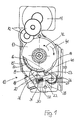
- FIG. 1 shows a side view of a belt retractor 10 shown on the penalty page; on this Function page is the vehicle sensitive and / or belt-sensitive controlled blocking system not visible; it is on the opposite side of the Belt retractor 10 housed and is usually from a coupled with the belt lock washer, the triggered in case of release in a housing-fixed gearing and a load-transfer connection between the the webbing force loaded shaft and the housing of the Belt retractor produces.
- Pre-locking device To cooperate with the additionally provided Pre-locking device has the clutch bell 15th an outer toothing 17, the one fixed to the housing Bearing 20 pivotally mounted two-armed toothed pulley 18 assigned.
- the toothed disc 18 carries on one arm a toothing 19 for cooperation with the External teeth 17 of the clutch bell 15 and is at her over the housing-fixed storage 20 protruding rear Arm 21 with the one end of a transmission lever 22nd connected, the other end to a toothed segment 23rd trained control segment is attached.
- the toothed segment 23 in turn is a housing-fixed storage 26th pivotally mounted, wherein the two end positions of the Tooth segment 23 with the engagement position of the toothed wheel 18 in the outer teeth 17 of the clutch bell 15th on the one hand and the release position of the toothed pulley 18 for the clutch bell 15 on the other hand correspond.
- FIG. 1 is the locking position of the toothed segment 23 represented in which the toothed segment 23 via the Transmission lever 22, the toothed disc 18 with their Gearing 19 in engagement with the external toothing 17 of the Clutch bell 15 has entered.
- a compression spring 32 biases the rear arm 21 such that the toothed disc 18 in Engagement with the external teeth 17 of the clutch bell 15th is held; but by the slot arrangement is ensures that the toothed disc 18 when Matterratschen the external teeth 17 of the clutch bell 15 the can perform desired evasive movements.
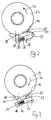
- Tooth segment 23 Insofar as in Figures 1 and 3, the locking position of Tooth segment 23 is shown, is the outer tooth 25th still engaged with the external teeth 14 of the Output gear 13, so that in a reverse rotation of the Output gear 13, the toothed segment 23 is taken, wherein during the further rotation of the output gear in the direction of Arrow 41, the external teeth 14 via the tooth 25 of the Zahnsegmentes 23 technicallyratscht.
- Toothed segment 23 should be able to perform evasive movements, is also this viewpoint by the arrangement a U-shaped leaf spring 28 by means of a Federhalters 27 is attached, taken into account.
- a U-shaped leaf spring 28 by means of a Federhalters 27 is attached, taken into account.
- the U-shaped leaf spring 28 is provided, whose two outer spring arms the toothed segment 23rd between them and on the one hand as a stop for the serve both positions of the toothed segment 23 and on the other hand for a corresponding spring preload to care.
- the seat belt retractor shown in Figure 4 has with the exception of the training of the transmission mechanism the the same structure as the belt retractor described for Figure 1, and to that extent is already on that of Figure 1 given explanation of the training as well as the function the belt retractor reference.
- the transmission mechanism from a meshing with the driven gear 13 Transmission wheel 50, which is for a reversal of the direction of rotation the output gear 13 is needed.
- the transmission wheel 50 in turn drives a clutch 51, which about one shown in detail in Figures 7 to 9 Axial coupling with the locking disc 18 is coupled. in the FIG.
- FIGS. 7 to 9 The construction of the axial coupling is shown in FIGS. 7 to 9 seen. It follows that the coupling 51 coaxially aligned with the axis of rotation of the toothed disc 18 and is arranged, wherein the coupling wheel 51 in one piece an axially projecting and the toothed disc with a paragraph comprising sleeve 52. Inside the sleeve 52 is a coupling element 53 axially displaceable, which, as seen from Figure 8, a form-fitting over a square training is connected to the coupling wheel 51, so that the coupling element 53 each with the coupling wheel 51 rotates, but in the interior of the sleeve 52 axially is displaceable. The axial displacement takes place against the Effect of a between the coupling element 53 and the Coupling 51 arranged spring 54, the Coupling element 53 in engagement with the toothed disc 18th biases.
- the coupling element 53 made of an elastic plastic formed so that only one return spring 54th is required.
- Coupling element 53 but also from an unyielding Material exist, and then it can be between the Pulley 18 and the coupling element 53 an additional Be arranged spring 57, which in the displacement of the Coupling element 53 this in its displacement movement catches before by hitting the coupling element at the toothed wheel 18 noise occurs.
Landscapes
- Engineering & Computer Science (AREA)
- Mechanical Engineering (AREA)
- Automotive Seat Belt Assembly (AREA)
- Pulleys (AREA)
- Devices For Conveying Motion By Means Of Endless Flexible Members (AREA)
Description
- Fig. 1
- einen Sicherheitsgurtaufroller mit Vorstraffeinrichtung und Vorverriegelungseinrichtung einer teilweise geschnittenen Seitenansicht,
- Fig. 2
- die Vorverriegelungseinrichtung in einer Einzeldarstellung in entriegeltem Zustand in der Lösestellung des Steuersegmentes,
- Fig. 3
- den Gegenstand der Figur 2 in verriegeltem Zustand der Vorverriegelungseinrichtung in der Riegelstellung des Steuersegmentes.
- Fig. 4
- ein anderes Ausführungsbeispiel des Sicherheitsgurtaufrollers mit Vorstraffeinrichtung und Vorverriegelungseinrichtung in einer Darstellung gemäß Figur 1,
- Fig. 5
- die Vorverriegelungseinrichtung mit verriegelter Zahnscheibe,
- Fig. 6
- den Gegenstand der Figur 5 bei entriegelter Zahnscheibe,
- Fig. 7
- die Zahnscheibe mit Kupplungsrad in einer geschnittenen Seitenansicht,
- Fig. 8
- den Gegenstand der Figur 7 in einer auseinandergezogenen Darstellung seiner Einzelteile,
- Fig. 9
- den Gegenstand der Figur 8 in einer anderen Ausführungsform.
Claims (22)
- Sicherheitsgurtaufroller (10), insbesondere für den Einsatz in Kraftfahrzeugen, mit einem fahrzeugsensitiv und/oder gurtbandsensitiv angesteuerten Blockiersystem und mit einer auf die Gurtwelle einwirkenden Straffeinrichtung, wobei die Gurtwelle mit einem von einem Elektromotor (11) als Strafferantrieb über ein zwischengeschaltetes Getriebe (12) angetriebenen Abtriebsrad (13) kuppelbar ist und das Getriebe (12) mindestens eine Schaltstellung zur Ausführung einer Vorabstraffung des Insassen durch Rückdrehung der Gurtwelle in Aufwickelrichtung aufweist, dadurch gekennzeichnet, dass im Bereich der Kupplung zwischen Abtriebsrad (13) und Gurtwelle eine über die Drehung des Abtriebsrades (13) in Gurteinzugsrichtung und in Gurtauszugsrichtung steuerbare und nur während des Straffvorganges wirksame Vorverriegelungseinrichtung (18; 22, 23; 50, 51, 53) für die Gurtwelle ausgebildet ist, deren Verriegelung mit der Gurtwelle bei Überschreiten einer vorbestimmten, in Gurtauszugsrichtung auf die Gurtwelle einwirkenden Last aufgehoben wird.
- Sicherheitsgurtaufroller nach Anspruch 1, dadurch gekennzeichnet, dass die Vorverriegelungseinrichtung durch eine am Gehäuse (40) zwischen einer Eingriffsstellung in eine an einer mit der Gurtwelle verbundenen Kupplungsglocke (15) ausgebildeten Außenverzahnung (17) und einer Freigabestellung schwenkbar gelagerte Zahnscheibe (18) gebildet ist, die über ein Getriebe (22, 23; 50, 51, 53) an das Abtriebsrad (13) kuppelbar ist.
- Sicherheitsgurtaufroller nach Anspruch 1 oder 2, dadurch gekennzeichnet, dass das Getriebe aus einem Übertragungsmechanismus mit einem mit seinem einen Ende an der Zahnscheibe (18) angreifenden und an seinem anderen Ende mit einem am Gehäuse (40) schwenkbar gelagerten Steuersegment (23) verbundenen Übertragungshebel (22) besteht.
- Sicherheitsgurtaufroller nach Anspruch 3, dadurch gekennzeichnet, dass das Steuersegment (23) von dem Abtriebsrad (13) zwischen einer die Zahnscheibe (18) außer Eingriff mit der Außenverzahnung (17) der Kupplungsglocke (15) haltenden Lösestellung und einer die Zahnscheibe (18) in Eingriff mit der Außenverzahnung (17) der Kupplungsglocke (15) steuernden Riegelstellung verschwenkbar ist.
- Sicherheitsgurtaufroller nach Anspruch 4, dadurch gekennzeichnet, dass zwischen Abtriebsrad (13) und Steuersegment (23) eine große Übersetzung ausgebildet ist.
- Sicherheitsgurtaufroller nach Anspruch 4 oder 5, dadurch gekennzeichnet, dass das Steuersegment als Zahnsegment (23) ausgebildet ist und mit einer an dem Abtriebsrad (13) ausgebildeten Außenverzahnung (14) zusammenwirkt.
- Sicherheitsgurtaufroller nach Anspruch 6, dadurch gekennzeichnet, dass das Zahnsegment (23) in seiner Lösestellung wie auch in seiner Riegelstellung jeweils mit wenigstens einem Zahn (25) in Kontakt mit der Außenverzahnung (14) des Abtriebsrades (13) verbleibt und bei Drehung des Abtriebsrades (13) die Außenverzahnung (14) des Abtriebsrades (13) in beiden Drehrichtungen jeweils über den in Eingriff stehenden Zahn (25) des Zahnsegmentes (23) hinwegratscht.
- Sicherheitsgurtaufroller nach Anspruch 7, dadurch gekennzeichnet, dass die Verzahnung (24) des Zahnsegmentes (23) elastisch ausgebildet ist.
- Sicherheitsgurtaufroller nach Anspruch 4 oder 5, dadurch gekennzeichnet, dass zwischen Steuersegment und Abtriebsrad (13) ein permanenter Reibschluss ausgebildet ist.
- Sicherheitsgurtaufroller nach einem der Ansprüche 4 bis 9, dadurch gekennzeichnet, dass das Steuersegment sowohl in seine Lösestellung als auch in seine Riegelstellung durch eine Feder (28) vorgespannt ist.
- Sicherheitsgurtaufroller nach Anspruch 10, dadurch gekennzeichnet, dass in der Verbindung zwischen Zahnscheibe (18) und Übertragungshebel (22) ein Spiel ausgebildet und die Zahnscheibe (18) mittels einer Feder (32) in ihre Eingriffsstellung mit der Außenverzahnung (17) der Kupplungsglocke (15) vorgespannt ist.
- Sicherheitsgurtaufroller nach Anspruch 1 oder 2, dadurch gekennzeichnet, dass das Getriebe aus einem mit dem Abtriebsrad (13) kämmenden Übertragungsrad (50) und einem davon angetriebenen Kupplungsrad (51) besteht, wobei die Verbindung zwischen der Zahnscheibe (18) und dem Kupplungsrad (51) reibschlüssig mit der Möglichkeit einer Relativbewegung von Zahnscheibe (18) und Kupplungsrad (51) zueinander ausgeführt ist.
- Sicherheitsgurtaufroller nach Anspruch 12, dadurch gekennzeichnet, dass das Kupplungsrad (51) koaxial zur Drehachse der Zahnscheibe (18) angeordnet ist und über ein in einer an dem Kupplungsrad (51) axial angeordneten Hülse (52) axial gegen Federwirkung verschiebbares Kupplungselement (53) auf die Zahnscheibe (18) einwirkt.
- Sicherheitsgurtaufroller nach Anspruch 13, dadurch gekennzeichnet, dass zwischen dem Kupplungselement (53) und dem Kupplungsrad (51) mit Hülse (52) eine das Kupplungselement (53) in Eingriff mit der Zahnscheibe (18) vorspannende Feder (54) angeordnet ist.
- Sicherheitsgurtaufroller nach einem der Ansprüche 12 bis 14, dadurch gekennzeichnet, dass an Kupplungselement (53) und Zahnscheibe (18) jeweils eine axial ineinandergreifende Verzahnung (55) mit axial vorstehenden Zahnflanken (56) ausgebildet ist und die Zahnflanken (56) bei der Relativdrehung von Kupplungselement (53) und Zahnscheibe (18) zueinander übereinander hinwegrutschen.
- Sicherheitsgurtaufroller nach Anspruch 15, dadurch gekennzeichnet, dass die Steigung der Zahnflanken (56) entgegen der Einsteuerungsrichtung der Zahnscheibe (18) in die Außenverzahnung (17) der Kupplungsglocke (15) steiler ausgebildet ist als in der Einsteuerungsrichtung.
- Sicherheitsgurtaufroller nach einem der Ansprüche 13 bis 16, dadurch gekennzeichnet, dass das Kupplungselement (53) aus einem elastomeren Material besteht.
- Sicherheitsgurtaufroller nach einem der Ansprüche 13 bis 16, dadurch gekennzeichnet, dass zwischen dem aus einem unnachgiebigen Material bestehenden Kupplungselement (53) und Zahnscheibe (18) eine zusätzliche Feder (57) angeordnet ist.
- Sicherheitsgurtaufroller nach einem der Ansprüche 1 bis 18, dadurch gekennzeichnet, dass die Verzahnung (19) der während des Straffvorgangs in Eingriff mit der Außenverzahnung (17) der Kupplungsglocke (15) eingesteuerten Zahnscheibe (18) derart ausgebildet ist, dass bei Drehung der Gurtwelle mit Kupplungsglocke (15) in Straffrichtung die Außenverzahnung (17) der Kupplungsglocke (15) über die Verzahnung (19) der Zahnscheibe (18) hinwegratscht.
- Sicherheitsgurtaufroller nach einem der Ansprüche 1 bis 19, dadurch gekennzeichnet, daß das Getriebe (22, 23; 50, 51, 53) derart ausgebildet ist, daß die Zahnscheibe (18) mit einem zeitlichen Versatz der Drehung des Abtriebsrades (13) in Gurtauszugsrichtung nachfolgt.
- Sicherheitsgurtaufroller nach Anspruch 20, dadurch gekennzeichnet, daß das Abtriebsrad (13) mit einem Freilauf an den Übertragungsmechanismus (22, 23) oder das Übertragungsrad (50) gekuppelt ist.
- Sicherheitsgurtaufroller nach einem der Ansprüche 1 bis 21, dadurch gekennzeichnet, daß die Lagerung der Zahnscheibe (18) derart ausgebildet ist, daß die Zahnscheibe (18) bei Drehung des Abtriebsrades (13) in Gurtauszugsrichtung vor ihrer Aussteuerung aus der Außenverzahnung (17) der Kupplungsglocke (15) über einen vorgegebenen Weg der Drehung der Kupplungsglocke (15) in Gurtauszugsrichtung nachfolgt.
Applications Claiming Priority (3)
| Application Number | Priority Date | Filing Date | Title |
|---|---|---|---|
| DE10064352 | 2000-12-21 | ||
| DE2000164352 DE10064352C1 (de) | 2000-12-21 | 2000-12-21 | Sicherheitsgurtaufroller mit einer Vorstraffeinrichtung |
| PCT/EP2001/010355 WO2002049886A1 (de) | 2000-12-21 | 2001-09-07 | Sicherheitsgurtaufroller mit einer vorstraffeinrichtung |
Publications (2)
| Publication Number | Publication Date |
|---|---|
| EP1345797A1 EP1345797A1 (de) | 2003-09-24 |
| EP1345797B1 true EP1345797B1 (de) | 2005-05-11 |
Family
ID=7668502
Family Applications (2)
| Application Number | Title | Priority Date | Filing Date |
|---|---|---|---|
| EP01974233A Expired - Lifetime EP1345797B1 (de) | 2000-12-21 | 2001-09-07 | Sicherheitsgurtaufroller mit einer vorstraffeinrichtung |
| EP01974333A Expired - Lifetime EP1551676B1 (de) | 2000-12-21 | 2001-10-08 | Sicherheitsgurtaufroller mit einer vorstraffeinrichtung |
Family Applications After (1)
| Application Number | Title | Priority Date | Filing Date |
|---|---|---|---|
| EP01974333A Expired - Lifetime EP1551676B1 (de) | 2000-12-21 | 2001-10-08 | Sicherheitsgurtaufroller mit einer vorstraffeinrichtung |
Country Status (5)
| Country | Link |
|---|---|
| EP (2) | EP1345797B1 (de) |
| JP (2) | JP4711102B2 (de) |
| AU (2) | AU2001293800A1 (de) |
| DE (3) | DE10064352C1 (de) |
| WO (2) | WO2002049886A1 (de) |
Families Citing this family (14)
| Publication number | Priority date | Publication date | Assignee | Title |
|---|---|---|---|---|
| JP5190434B2 (ja) * | 1999-01-19 | 2013-04-24 | タカタ株式会社 | シートベルト巻取装置及び制御方法 |
| DE10342229A1 (de) * | 2003-09-11 | 2005-05-04 | Autoliv Dev | Gurtaufroller mit pyrotechnischem Vorstrafferantrieb |
| DE102004012166A1 (de) | 2004-03-09 | 2005-10-06 | Takata Corp. | Gurtstraffer |
| DE102004012164A1 (de) | 2004-03-09 | 2005-10-06 | Takata Corp. | Gurtstraffer |
| DE102004012165A1 (de) | 2004-03-09 | 2005-10-06 | Takata Corp. | Gurtstraffer |
| JP4702832B2 (ja) * | 2005-05-26 | 2011-06-15 | タカタ株式会社 | シートベルトリトラクタおよびこれを用いたシートベルト装置 |
| DE102006014295A1 (de) * | 2006-03-28 | 2007-10-04 | Trw Automotive Gmbh | Verfahren zur Steuerung eines Fahrzeuginsassen-Rückhaltesystems sowie Insassen-Rückhaltesystem für ein Kraftfahrzeug0 |
| JP4980174B2 (ja) * | 2007-08-24 | 2012-07-18 | タカタ株式会社 | シートベルトリトラクタおよびこれを備えたシートベルト装置 |
| DE102007056816B4 (de) | 2007-11-23 | 2015-09-10 | Autoliv Development Ab | Aufroller für das Gurtband eines Sicherheitsgurtsystems |
| ATE510734T1 (de) * | 2007-11-27 | 2011-06-15 | Autoliv Dev | Reversibler gurtstraffer |
| DE102012200281B4 (de) * | 2012-01-11 | 2017-09-21 | Autoliv Development Ab | Gurtaufroller mit einer Straffeinrichtung und einer Kraftbegrenzungseinrichtung |
| DE102013010770A1 (de) | 2013-06-28 | 2014-12-31 | Autoliv Development Ab | Sicherheitsgurt-Vorrichtung, Verfahren zum Betreiben einer Sicherheitsgurt-Vorrichtung sowie Verwendungen |
| US20170015275A1 (en) * | 2015-07-17 | 2017-01-19 | Shield Restraint Systems, Inc. | Prelock prevention device for use with a web retractor and associated systems and methods |
| DE102016225096B4 (de) * | 2016-12-15 | 2019-05-29 | Joyson Safety Systems Germany Gmbh | Aufrolleinrichtung für einen Sicherheitsgurt eines Gurtaufrollers |
Family Cites Families (10)
| Publication number | Priority date | Publication date | Assignee | Title |
|---|---|---|---|---|
| DE3019298A1 (de) * | 1980-05-21 | 1981-11-26 | Autoflug Gmbh, 2084 Rellingen | Automatischer gurtaufroller fuer sicherheitsgurte, insbesondere in kraftfahrzeugen |
| US4524981A (en) * | 1983-11-22 | 1985-06-25 | Smith International, Inc. | Annular seal with V-cut |
| DE4314153A1 (de) * | 1993-04-29 | 1994-11-03 | Hs Tech & Design | Sicherheitsgurtaufrollautomat |
| DE19513724A1 (de) * | 1995-04-11 | 1996-10-17 | Trw Repa Gmbh | Gurtaufroller für ein Fahrzeugsicherheitsgurtsystem |
| DE19524162A1 (de) * | 1995-07-03 | 1997-01-09 | Trw Repa Gmbh | Gurtaufroller für einen Sicherheitsgurt |
| JP4142750B2 (ja) * | 1995-09-08 | 2008-09-03 | タカタ株式会社 | 車両の乗員拘束保護システム |
| DE19648515A1 (de) * | 1996-11-22 | 1998-05-28 | Takata Europ Gmbh | Sicherheitsgurtvorrichtung für Kraftfahrzeuge |
| DE19731689C2 (de) * | 1997-07-23 | 1999-07-29 | Hs Tech & Design | Vorrichtung zum Aufrollen eines Sicherheitsgurtbandes |
| AU4006799A (en) * | 1999-05-20 | 2000-12-12 | Breed Automotive Technology, Inc. | Seatbelt retractor |
| DE19951791A1 (de) * | 1999-10-27 | 2001-05-03 | Breed Automotive Tech | Kindersitz-Verriegelungseinrichtung für einen Sicherheitsgurt-Aufrollautomaten |
-
2000
- 2000-12-21 DE DE2000164352 patent/DE10064352C1/de not_active Expired - Fee Related
-
2001
- 2001-09-07 AU AU2001293800A patent/AU2001293800A1/en not_active Abandoned
- 2001-09-07 DE DE50106229T patent/DE50106229D1/de not_active Expired - Lifetime
- 2001-09-07 WO PCT/EP2001/010355 patent/WO2002049886A1/de not_active Ceased
- 2001-09-07 EP EP01974233A patent/EP1345797B1/de not_active Expired - Lifetime
- 2001-09-07 JP JP2002551404A patent/JP4711102B2/ja not_active Expired - Lifetime
- 2001-10-08 DE DE50109653T patent/DE50109653D1/de not_active Expired - Lifetime
- 2001-10-08 JP JP2002551405A patent/JP3940921B2/ja not_active Expired - Lifetime
- 2001-10-08 EP EP01974333A patent/EP1551676B1/de not_active Expired - Lifetime
- 2001-10-08 WO PCT/EP2001/011591 patent/WO2002049887A1/de not_active Ceased
- 2001-10-08 AU AU2001293868A patent/AU2001293868A1/en not_active Abandoned
Also Published As
| Publication number | Publication date |
|---|---|
| AU2001293868A1 (en) | 2002-07-01 |
| DE50109653D1 (de) | 2006-06-01 |
| DE10064352C1 (de) | 2002-03-21 |
| EP1345797A1 (de) | 2003-09-24 |
| JP2004532150A (ja) | 2004-10-21 |
| JP3940921B2 (ja) | 2007-07-04 |
| WO2002049887A1 (de) | 2002-06-27 |
| WO2002049886A1 (de) | 2002-06-27 |
| DE50106229D1 (de) | 2005-06-16 |
| AU2001293800A1 (en) | 2002-07-01 |
| EP1551676B1 (de) | 2006-04-26 |
| JP2004516180A (ja) | 2004-06-03 |
| JP4711102B2 (ja) | 2011-06-29 |
| EP1551676A1 (de) | 2005-07-13 |
Similar Documents
| Publication | Publication Date | Title |
|---|---|---|
| DE4331027C2 (de) | Gurtaufroller-Gurtstrammer-Kombination mit Kraftbegrenzer | |
| DE10204477B4 (de) | Gurtstraffer | |
| DE602004002641T2 (de) | Gurtaufroller für einen Sicherheitsgurt | |
| DE4345457C2 (de) | Gurtaufroller-Gurtstrammer-Kombination mit Kraftbegrenzer | |
| WO2003082640A1 (de) | Leistungsstraffer | |
| EP0627345A1 (de) | Sicherheitsgurtaufroller | |
| DE202004009949U1 (de) | Aufwickelvorrichtung für einen Sicherheitsgurt eines Fahrzeugs | |
| DE10204475B4 (de) | Gurtstraffer | |
| DE10025031B4 (de) | Sicherheitsgurtsystem mit elektrischem Antrieb seiner Komponenten | |
| DE102020207535A1 (de) | Gurtaufroller | |
| DE10122910A1 (de) | Rückhaltevorrichtung für einen Fahrzeuginsassen | |
| DE10064352C1 (de) | Sicherheitsgurtaufroller mit einer Vorstraffeinrichtung | |
| DE102018116126B4 (de) | Gurtaufroller für eine Sicherheitsgurteinrichtung eines Kraftfahrzeuges | |
| DE2727470A1 (de) | Sicherheitsgurteinrichtung fuer fahrzeuge, insbesondere kraftfahrzeuge | |
| EP1963146B1 (de) | Sicherheitsgurtaufroller mit gurtauszugsgesteuerter kraftbegrenzungsvorrichtung | |
| DE102007008495B4 (de) | Gurtaufroller für ein Sicherheitsgurtsystem | |
| EP1658208A1 (de) | Gurtaufroller mit zwei straffvorrichtungen | |
| EP1414681B1 (de) | Sicherheitsgurtaufroller mit einer in abhängigkeit vom gurtbandauszug schaltbaren kraftbegrenzungseinrichtung | |
| DE10027599C1 (de) | Sicherheitsgurtaufroller mit reversiblem Strafferantrieb | |
| DE4206983C2 (de) | Gurtstraffer für einen Fahrzeugsicherheitsgurt | |
| EP1280684B1 (de) | Sicherheitsgurtaufroller mit einem reversiblen gurtstraffer | |
| DE3509254A1 (de) | Sicherheitsgurtaufroller | |
| DE102004027135A1 (de) | Verfahren zum Betreiben eines Gurtaufrollers sowie Gurtaufroller für einen Sicherheitsgurt | |
| DE102004022134A1 (de) | Gurtaufroller für einen Fahrzeugsicherheitsgurt | |
| DE3600003C2 (de) |
Legal Events
| Date | Code | Title | Description |
|---|---|---|---|
| PUAI | Public reference made under article 153(3) epc to a published international application that has entered the european phase |
Free format text: ORIGINAL CODE: 0009012 |
|
| 17P | Request for examination filed |
Effective date: 20030613 |
|
| AK | Designated contracting states |
Kind code of ref document: A1 Designated state(s): AT BE CH CY DE DK ES FI FR GB GR IE IT LI LU MC NL PT SE TR |
|
| AX | Request for extension of the european patent |
Extension state: AL LT LV MK RO SI |
|
| RBV | Designated contracting states (corrected) |
Designated state(s): AT BE DE FR |
|
| GRAP | Despatch of communication of intention to grant a patent |
Free format text: ORIGINAL CODE: EPIDOSNIGR1 |
|
| GRAS | Grant fee paid |
Free format text: ORIGINAL CODE: EPIDOSNIGR3 |
|
| GRAA | (expected) grant |
Free format text: ORIGINAL CODE: 0009210 |
|
| AK | Designated contracting states |
Kind code of ref document: B1 Designated state(s): DE FR |
|
| RBV | Designated contracting states (corrected) |
Designated state(s): DE FR |
|
| REG | Reference to a national code |
Ref country code: IE Ref legal event code: FG4D Free format text: LANGUAGE OF EP DOCUMENT: GERMAN |
|
| REF | Corresponds to: |
Ref document number: 50106229 Country of ref document: DE Date of ref document: 20050616 Kind code of ref document: P |
|
| PLBE | No opposition filed within time limit |
Free format text: ORIGINAL CODE: 0009261 |
|
| STAA | Information on the status of an ep patent application or granted ep patent |
Free format text: STATUS: NO OPPOSITION FILED WITHIN TIME LIMIT |
|
| ET | Fr: translation filed | ||
| 26N | No opposition filed |
Effective date: 20060214 |
|
| REG | Reference to a national code |
Ref country code: FR Ref legal event code: PLFP Year of fee payment: 16 |
|
| REG | Reference to a national code |
Ref country code: FR Ref legal event code: PLFP Year of fee payment: 17 |
|
| REG | Reference to a national code |
Ref country code: FR Ref legal event code: PLFP Year of fee payment: 18 |
|
| PGFP | Annual fee paid to national office [announced via postgrant information from national office to epo] |
Ref country code: FR Payment date: 20200928 Year of fee payment: 20 Ref country code: DE Payment date: 20200924 Year of fee payment: 20 |
|
| REG | Reference to a national code |
Ref country code: DE Ref legal event code: R071 Ref document number: 50106229 Country of ref document: DE |