EP1343034B1 - Verfahren und Vorrichtung zur Herstellung eines Lichtwellenleiterendes - Google Patents
Verfahren und Vorrichtung zur Herstellung eines Lichtwellenleiterendes Download PDFInfo
- Publication number
- EP1343034B1 EP1343034B1 EP03004045A EP03004045A EP1343034B1 EP 1343034 B1 EP1343034 B1 EP 1343034B1 EP 03004045 A EP03004045 A EP 03004045A EP 03004045 A EP03004045 A EP 03004045A EP 1343034 B1 EP1343034 B1 EP 1343034B1
- Authority
- EP
- European Patent Office
- Prior art keywords
- optical waveguide
- tool
- cut
- end faces
- severing
- Prior art date
- Legal status (The legal status is an assumption and is not a legal conclusion. Google has not performed a legal analysis and makes no representation as to the accuracy of the status listed.)
- Expired - Lifetime
Links
- 238000000034 method Methods 0.000 title claims abstract description 20
- 230000003287 optical effect Effects 0.000 title claims description 47
- 238000004519 manufacturing process Methods 0.000 title description 2
- 238000005520 cutting process Methods 0.000 claims abstract description 25
- 238000000227 grinding Methods 0.000 claims description 6
- 238000003754 machining Methods 0.000 claims description 5
- 239000010432 diamond Substances 0.000 claims description 2
- 238000003801 milling Methods 0.000 claims description 2
- 239000011248 coating agent Substances 0.000 claims 1
- 238000000576 coating method Methods 0.000 claims 1
- 239000013307 optical fiber Substances 0.000 description 16
- 239000000835 fiber Substances 0.000 description 7
- 230000001419 dependent effect Effects 0.000 description 1
Images


Classifications
-
- G—PHYSICS
- G02—OPTICS
- G02B—OPTICAL ELEMENTS, SYSTEMS OR APPARATUS
- G02B6/00—Light guides; Structural details of arrangements comprising light guides and other optical elements, e.g. couplings
- G02B6/24—Coupling light guides
- G02B6/245—Removing protective coverings of light guides before coupling
-
- G—PHYSICS
- G02—OPTICS
- G02B—OPTICAL ELEMENTS, SYSTEMS OR APPARATUS
- G02B6/00—Light guides; Structural details of arrangements comprising light guides and other optical elements, e.g. couplings
- G02B6/24—Coupling light guides
- G02B6/25—Preparing the ends of light guides for coupling, e.g. cutting
-
- G—PHYSICS
- G02—OPTICS
- G02B—OPTICAL ELEMENTS, SYSTEMS OR APPARATUS
- G02B6/00—Light guides; Structural details of arrangements comprising light guides and other optical elements, e.g. couplings
- G02B6/24—Coupling light guides
- G02B6/36—Mechanical coupling means
- G02B6/38—Mechanical coupling means having fibre to fibre mating means
- G02B6/3807—Dismountable connectors, i.e. comprising plugs
- G02B6/3833—Details of mounting fibres in ferrules; Assembly methods; Manufacture
- G02B6/3863—Details of mounting fibres in ferrules; Assembly methods; Manufacture fabricated by using polishing techniques
Definitions
- the invention relates to a method and a device for Production of a transparent to light waves end face provided Lichtwellenielterendes for the attachment of a ferrule, wherein the end face by cutting the optical fiber and mechanical Processing is formed and the optical fiber in the area of his End section is freed from its outer jacket, the optical fiber outside completely encloses.
- the end faces of very well in position to position and hold light-conducting fiber. Both in the radial and in the axial direction, the end faces are exact to position each other.
- Ferrule used, which are placed on the end of an optical waveguide. The attachment of the ferrule on the optical fiber end tensile strength must be without the optical fiber is damaged or his optical properties are affected.
- the end faces of the optical fiber ends must be finished very accurately be.
- the invention is based on the object, a simpler way for the To find an exact face at an optical fiber end, which also allows a high number of pieces in the shortest possible time.
- the optical waveguide is severed and at the same time the mechanical processing of the end face carried out. Then, in a predetermined end portion of the Optical waveguide severed its outer jacket and the optical waveguide deducted.
- a saw-grinding sheet used for cutting through the fiber optic cable and fine machining its End face.
- a Saw-sanding sheet can cut through the optical fiber and at the same time its End faces are ground.
- a saw-grinding sheet is preferably a used diamond-tipped disc.
- the device for carrying out the method is with a Clamping device for clamping the optical waveguide, a Cutting tool for cutting the optical fiber transversely to his Longitudinal direction, which simultaneously perform the finishing of the end faces can and a forming knife, for cutting through the outer jacket of the Fiber optic provided.
- the cutting tool is parallel with two mutually extending side surfaces provided for the finishing the end faces are suitable and can be guided along the end surfaces.
- the cutting tool by a milling and or grinding tool educated. This cutting tool is transverse to the longitudinal direction of the Fiber optic movable back and forth.
- the device has a combined conveying and tensioning device for the longitudinal movement of the Optical waveguide, which holds with the optical waveguide Clamping device cooperates with separating tool and cutting blade.
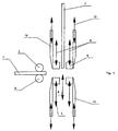
- the method is based on the essential required Machine parts shown schematically.
- the inserted arrows is the Direction of movement of the individual parts or of the optical waveguide displayed.
- the device is a mirror image executed so that two optical fiber ends are produced simultaneously.
- Fig. 1 the device is shown in its normal position.
- the optical fiber 1 is held in the combined conveying and tensioning device 2 and can for the cutting and editing process to the right in the clamping and cutting parts of the device be inserted.
- the Jaws 4 and 5 are provided for the clamping of the optical waveguide 1 .
- the jaws 4 and 5 are like with the Arrows 6 indicated to move transversely to the optical waveguide 1.
- the cutting tool 7 is present, which according to Arrow 8 can be moved transversely to the optical waveguide 1.
- the cutting blades 10 and 11 are present, which, as indicated by the arrows 12, in the direction of the optical waveguide 1 can be moved back and forth.
- a second conveying and tensioning device 13 for receiving the Fiber optic 1 available.
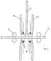
- the optical waveguide 1 by means of the conveyor and Clamping devices 2 and 13 in a predetermined length in the device introduced.
- the jaws 4 and 5 are closed and are firmly on Optical waveguide 1 on.
- the optical waveguide 1 in a predetermined position held firmly in the device.
- Saw and sanding sheet 7 and the cutting blades 1,11 are still in their starting position.
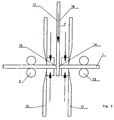
- Fig. 3 the severing of the optical waveguide with the Cutting tool 7 with simultaneous fine machining of the Cutting through resulting faces 14 and 15 completed.
- Separating tool 7 is a saw-grinding sheet is used, which on his Side surfaces 16 and 17 are equipped with diamonds.
- the optical waveguide 1 by the clamping device of the jaws 4 and 5 held.
- the form knives 10 and 11 are still in their Starting position.
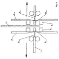
- the form knives 10 and 11 are retracted and the outer jacket of the optical waveguide severed.
- On the left side of the figure is a Side view of a cutting knife 10 shown.
- the cutting edge 20 of the Disconnecting blade 10 is semicircular with a diameter, which the outer diameter of the inner jacket of the optical waveguide. 1 corresponds so that when pushing together two cutting blades 10 and 11, the outer jacket of the optical waveguide 1 is completely severed.
- FIG. 5 shows the next method step, in which the clamping jaws 4 and 5 of the clamping device are opened. Subsequently, as in FIG. 6 represented, the optical waveguide 1 on each side of the device to the outside pulled, whereby the end portions 21 and 22 of the outer shell, by the closed form knives 10 and 11 are held by the Fiber optic ends 23 and 24 are stripped off.
Landscapes
- Physics & Mathematics (AREA)
- General Physics & Mathematics (AREA)
- Optics & Photonics (AREA)
- Light Guides In General And Applications Therefor (AREA)
- Mechanical Coupling Of Light Guides (AREA)
- Optical Integrated Circuits (AREA)
- Knives (AREA)
- Manufacture, Treatment Of Glass Fibers (AREA)
- Ropes Or Cables (AREA)
- Grinding And Polishing Of Tertiary Curved Surfaces And Surfaces With Complex Shapes (AREA)
Description
- Fig. 1
- die wesentlichen Teile der Vorrichtung in ihrer Grundstellung,
- Fig. 2
- die Vorrichtung mit eingeführtem und eingespanntem Lichtwellenleiter,
- Fig. 3
- den Durchtrennvorgang mit gleichzeitiger Bearbeitung der Stirnflächen,
- Fig. 4
- das Durchschneiden des Außenmantels,
- Fig. 5
- die Freigabe des Lichtwellenleiters durch die Spanneinrichtung und
- Fig. 6
- das Abziehen des Endabschnitts des Außenmantels vom Lichtwellenleiter
Claims (10)
- Verfahren zur Herstellung eines mit einer für Lichtwellen durchlässigen Stirnfläche versehenen lichtwellenleiters für die Anbringung einer Ferrule, bei dem die Stirnfläche durch Durchtrennen des Lichtwellenleiters unter mechanischer Bearbeitung gebildet wird und der Lichtwellenleiter im Bereich eines Endabschnitts von seinem Außenmantel befreit wird, der den Lichtwellenleiter außenseitig ganz umschließt, dadurch gekennzeichnet, dass das Durchtrennen des Lichtwellenleiters (1) und das mechanische Bearbeiten der Stirnflächen (14,15) als ein in sich geschlossener Arbeitsschritt ausgeführt wird, der zugleich das Durchtrennen des Lichtwellenleiters und die Feinbearbeitung der hierbei erhaltenen Stirnflächen (14,15) beinhaltet und dass das Entfernen der Außenmäntel (21,22) im Bereich der Endabschnitte (23,24) im Anschluss an diesen Arbeitsschritt vollzogen wird.
- Verfahren nach Anspruch 1 dadurch gekennzeichnet, dass für das Durchtrennen des Lichtwellenleiters (1) und die Feinbearbeitung der Stirnflächen (14,15) ein Säge-Schleifblatt (7) verwendet wird, das auf seinen Seitenflächen eine Beschichtung zum Schleifen der Stimflächen (14,15) hat.
- Verfahren nach Anspruch 2, dadurch gekennzeichnet, dass als Säge-Schleifblatt (7) eine diamantbestückte Scheibe verwendet wird.
- Verfahren nach Anspruch 1 bis 3, dadurch gekennzeichnet, dass die Endabschnitte der Außenmäntel (21,22) mittels eines Formmessers (10,11) von den übrigen Außenmänteln abgetrennt und nachfolgend von den Lichtwellenleitern abgezogen werden.
- Verfahren nach Anspruch 4, dadurch gekennzeichnet, dass, dass das Abziehen der Endabschnitte der Außenmäntel durch eine parallel zu dem Lichtwellenleiter (1) gerichtete Relativbewegung der Formmesser (10, 11) und einer Spanneinrichtung (2, 13) für den Lichtwellenleiter (1) bewirkt wird.
- Verfahren nach Anspruch 4, dadurch gekennzeichnet, dass das Abziehen des Außenmantels durch eine Rückwärtsbewegung der den Lichtwellenleiter (1) haltenden Spanneinrichtung (2,13) bewirkt wird.
- Vorrichtung zur Durchführung des Verfahrens nach einem der Ansprüche 1 bis 6, umfassend zumindest eine Klemmeinrichtung, eine Trennwerkzeug und Mittel zum Entfernen des Außenmantels im Bereich eines Endabschnitts von dem Lichtwellenleiter, dadurch gekennzeichnet, dass das Trennwerkzeug (7) quer zur Längsrichtung des Lichtwellenleiters (1) bewegbar ist und parallele Seitenflächen hat, die an den Stirnflächen entlangführbar sind.
- Vorrichtung nach Anspruch 7, dadurch gekennzeichnet, dass das Trennwerkzeug (7) durch ein Fräs- und/oder Schleifwerkzeug gebildet ist.
- Vorrichtung nach Anspruch 7 oder 8, dadurch gekennzeichnet, dass das Trennwerkzeug (7) quer zur Längsrichtung des Lichtwellenleiters (1) hin und her bewegbar ist.
- Vorrichtung nach Anspruch 7 bis 9, dadurch gekennzeichnet, dass die Vorrichtung eine kombinierte Förder- und Spanneinrichtung (2, 13) für die Längsbewegung des Lichtwellenleiters (1) sowie eine den Lichtwellenleiter (1) festhaltende Klemmeinrichtung (4,5) mit Trennwerkzeug (7) und Schneidmesser (10, 11) hat.
Applications Claiming Priority (2)
| Application Number | Priority Date | Filing Date | Title |
|---|---|---|---|
| DE10209461 | 2002-03-05 | ||
| DE10209461A DE10209461A1 (de) | 2002-03-05 | 2002-03-05 | Verfahren und Vorrichtung zur Herstellung eines Lichtwellenleiterendes |
Publications (2)
| Publication Number | Publication Date |
|---|---|
| EP1343034A1 EP1343034A1 (de) | 2003-09-10 |
| EP1343034B1 true EP1343034B1 (de) | 2005-05-11 |
Family
ID=27740625
Family Applications (1)
| Application Number | Title | Priority Date | Filing Date |
|---|---|---|---|
| EP03004045A Expired - Lifetime EP1343034B1 (de) | 2002-03-05 | 2003-02-25 | Verfahren und Vorrichtung zur Herstellung eines Lichtwellenleiterendes |
Country Status (6)
| Country | Link |
|---|---|
| US (1) | US7056031B2 (de) |
| EP (1) | EP1343034B1 (de) |
| AT (1) | ATE295547T1 (de) |
| DE (2) | DE10209461A1 (de) |
| ES (1) | ES2240870T3 (de) |
| HU (1) | HU228970B1 (de) |
Families Citing this family (3)
| Publication number | Priority date | Publication date | Assignee | Title |
|---|---|---|---|---|
| DE10303741A1 (de) * | 2003-01-30 | 2004-08-12 | Fraunhofer-Gesellschaft zur Förderung der angewandten Forschung e.V. | Verfahren zum Trennen eines lang gestreckten Formkörpers, insbesondere einer polymeroptischen Faser |
| WO2006006131A1 (de) * | 2004-07-09 | 2006-01-19 | Schleuniger Holding Ag | Verfahren und vorrichtung zum durchtrennen und endbearbeiten von lichtwellenleitern |
| US8651751B2 (en) * | 2011-11-15 | 2014-02-18 | Chromis Fiberoptics, Inc. | Apparatus and process for termination of polymer optical fiber ribbons |
Family Cites Families (13)
| Publication number | Priority date | Publication date | Assignee | Title |
|---|---|---|---|---|
| US3819442A (en) * | 1972-04-04 | 1974-06-25 | Us Health Education & Welfare | Alignment techniques for fiber bundles |
| FR2385107A1 (fr) * | 1977-01-18 | 1978-10-20 | Souriau & Cie | Perfectionnements aux procedes pour preparer, en vue de sa connexion, une extremite d'un cable optique a faisceau de fibres et cable ainsi obtenu |
| GB1604957A (en) * | 1978-05-26 | 1981-12-16 | Shin Meiwa Ind Co Ltd | Apparatus for collecting cut lengths of wire |
| US4422715A (en) * | 1981-06-22 | 1983-12-27 | Thomas & Betts Corporation | Fiber optic connector having fiber cutting means |
| JPS623208A (ja) * | 1985-06-28 | 1987-01-09 | Sumitomo Electric Ind Ltd | 光フアイバの接続方法 |
| CA2053010C (en) * | 1990-10-17 | 2001-05-01 | Claude Ricard | Processes and devices for the automatic connection of conductor wire or optical fiber section ends to adapted component receptacles |
| US5269206A (en) * | 1991-02-28 | 1993-12-14 | Amp Incorporated | Cable stripping apparatus |
| FR2757958B1 (fr) * | 1996-12-30 | 1999-01-22 | Alsthom Cge Alcatel | Outil de raccordement d'une fibre a une autre fibre ou a un element de connectique optique par l'intermediaire d'un module de raccordement |
| JP3272283B2 (ja) * | 1997-11-14 | 2002-04-08 | 富士通株式会社 | 電子データ保管装置 |
| US6530021B1 (en) * | 1998-07-20 | 2003-03-04 | Koninklijke Philips Electronics N.V. | Method and system for preventing unauthorized playback of broadcasted digital data streams |
| DE19842122C2 (de) * | 1998-09-05 | 2002-03-14 | Rennsteig Werkzeuge Gmbh | Zangenartig zu handhabendes Werkzeug |
| DE19919428C2 (de) | 1999-04-28 | 2001-12-06 | Tyco Electronics Logistics Ag | Kunststoff-Ferrule für einen Lichtwellenleiter und Verfahren zum Befestigen einer Ferrule an einem Lichtwellenleiter |
| US6361220B1 (en) * | 2000-10-02 | 2002-03-26 | Paul M. Mulligan | Terminal end of a connector on an optical fiber |
-
2002
- 2002-03-05 DE DE10209461A patent/DE10209461A1/de not_active Withdrawn
-
2003
- 2003-02-25 DE DE50300522T patent/DE50300522D1/de not_active Expired - Lifetime
- 2003-02-25 AT AT03004045T patent/ATE295547T1/de not_active IP Right Cessation
- 2003-02-25 ES ES03004045T patent/ES2240870T3/es not_active Expired - Lifetime
- 2003-02-25 EP EP03004045A patent/EP1343034B1/de not_active Expired - Lifetime
- 2003-03-04 HU HU0300529A patent/HU228970B1/hu unknown
- 2003-04-02 US US10/405,536 patent/US7056031B2/en not_active Expired - Lifetime
Also Published As
| Publication number | Publication date |
|---|---|
| HU228970B1 (en) | 2013-07-29 |
| ATE295547T1 (de) | 2005-05-15 |
| HUP0300529A2 (hu) | 2004-03-29 |
| DE10209461A1 (de) | 2003-10-02 |
| EP1343034A1 (de) | 2003-09-10 |
| US7056031B2 (en) | 2006-06-06 |
| HUP0300529A3 (en) | 2006-06-28 |
| ES2240870T3 (es) | 2005-10-16 |
| DE50300522D1 (de) | 2005-06-16 |
| US20030206702A1 (en) | 2003-11-06 |
| HU0300529D0 (en) | 2003-05-28 |
Similar Documents
| Publication | Publication Date | Title |
|---|---|---|
| DE2857349C2 (de) | Verfahren zum Abtrennen eines optischen Faserkabelstrangs und Glätten der Vorderfläche des Kabels | |
| DE69427930T2 (de) | Gerät zum Schneiden einer schrägen Endfläche durch ein Endstück von Fasern eines Fiberbandes | |
| DE3888749T2 (de) | Herstellungsmethode eines wirtschaftlichen Faserkopplers. | |
| DE4314692C2 (de) | Verfahren und Vorrichtung zur Herstellung von Bürsten | |
| DE2557660A1 (de) | Verfahren und vorrichtung zum spleissen optischer fasern | |
| DE69207846T2 (de) | Verfahren zum Schneiden einer optischen Faser | |
| DE4328126A1 (de) | Schneidverfahren und Vorrichtung zum Entfernen einer zweiten Überzugsschicht von einer ummantelten optischen Faser | |
| DE102009035839A1 (de) | Vorrichtung zum mechanischen Bearbeiten von rohr- oder stangenförmigen Werkstücken | |
| DE2851625A1 (de) | Wellenlaengen-demultiplexer und verfahren zur herstellung eines solchen demultiplexers | |
| DE4236251A1 (de) | Vorrichtung zum Entfernen der Schutzhülle von Optischen Fasern | |
| DE69203567T2 (de) | Verfahren und Vorrichtung zum Läppen der Bohrung einer keramischen Hülse. | |
| DE3236149A1 (de) | Verfahren zur herstellung von lichtwellenleiter-abzweigern und -multi-/demultiplexern nach dem strahlteilerprinzip | |
| EP1343034A1 (de) | Verfahren und Vorrichtung zur Herstellung eines Lichtwellenleiterendes | |
| EP1459116A1 (de) | VERFAHREN ZUM TRENNEN VON LICHTLEITFASERN MITTELS CO sb 2 /sb −LASERSTRAHLUNG | |
| WO2002077681A2 (de) | Bearbeiten einer isolierten optischen faser | |
| EP1685436B1 (de) | Verfahren zum erzeugen von planfl chen am umfang optischer p olymerfasern runden querschnitts | |
| DE3842754A1 (de) | Schneidevorrichtung fuer das selektive durchtrennen der mehrlagigen ummantelung eines kabels | |
| DE102015221637A1 (de) | 21Schnittlängenanzeigevorrichtung | |
| EP0874257B1 (de) | Verfahren zur Konfektionierung eines Polymer-Lichtwellenleiters mit einem Steckerstift | |
| DE69212109T2 (de) | Bearbeitungsmethode von Aussendurchmesser einer keramischen Hülse | |
| DE19910260B4 (de) | Vorrichtung zur Bearbeitung eines Endes eines Werkstücks | |
| EP1320775A2 (de) | Vorrichtung zum schneiden von polymeren optischen faserlichtwellenleitern (pof-lwl) | |
| DE2812208A1 (de) | Verfahren und vorrichtung zur verseilung von strangfoermigem gut groesseren querschnitts | |
| DE4208601C2 (de) | ||
| DE3925850A1 (de) | Verfahren zum absetzen von kabeln, insbesondere von lichtwellenleiterkabeln |
Legal Events
| Date | Code | Title | Description |
|---|---|---|---|
| PUAI | Public reference made under article 153(3) epc to a published international application that has entered the european phase |
Free format text: ORIGINAL CODE: 0009012 |
|
| AK | Designated contracting states |
Kind code of ref document: A1 Designated state(s): AT BE BG CH CY CZ DE DK EE ES FI FR GB GR HU IE IT LI LU MC NL PT SE SI SK TR |
|
| AX | Request for extension of the european patent |
Extension state: AL LT LV MK RO |
|
| 17P | Request for examination filed |
Effective date: 20030718 |
|
| 17Q | First examination report despatched |
Effective date: 20031016 |
|
| AKX | Designation fees paid | ||
| RBV | Designated contracting states (corrected) |
Designated state(s): AT BE BG CH CY CZ DE DK EE ES FI FR GB GR HU IE IT LI LU MC NL PT SE SI SK TR |
|
| REG | Reference to a national code |
Ref country code: DE Ref legal event code: 8566 |
|
| GRAP | Despatch of communication of intention to grant a patent |
Free format text: ORIGINAL CODE: EPIDOSNIGR1 |
|
| GRAS | Grant fee paid |
Free format text: ORIGINAL CODE: EPIDOSNIGR3 |
|
| GRAA | (expected) grant |
Free format text: ORIGINAL CODE: 0009210 |
|
| AK | Designated contracting states |
Kind code of ref document: B1 Designated state(s): AT BE BG CH CY CZ DE DK EE ES FI FR GB GR HU IE IT LI LU MC NL PT SE SI SK TR |
|
| PG25 | Lapsed in a contracting state [announced via postgrant information from national office to epo] |
Ref country code: NL Free format text: LAPSE BECAUSE OF FAILURE TO SUBMIT A TRANSLATION OF THE DESCRIPTION OR TO PAY THE FEE WITHIN THE PRESCRIBED TIME-LIMIT Effective date: 20050511 Ref country code: SI Free format text: LAPSE BECAUSE OF FAILURE TO SUBMIT A TRANSLATION OF THE DESCRIPTION OR TO PAY THE FEE WITHIN THE PRESCRIBED TIME-LIMIT Effective date: 20050511 Ref country code: FI Free format text: LAPSE BECAUSE OF FAILURE TO SUBMIT A TRANSLATION OF THE DESCRIPTION OR TO PAY THE FEE WITHIN THE PRESCRIBED TIME-LIMIT Effective date: 20050511 Ref country code: SK Free format text: LAPSE BECAUSE OF FAILURE TO SUBMIT A TRANSLATION OF THE DESCRIPTION OR TO PAY THE FEE WITHIN THE PRESCRIBED TIME-LIMIT Effective date: 20050511 Ref country code: CZ Free format text: LAPSE BECAUSE OF FAILURE TO SUBMIT A TRANSLATION OF THE DESCRIPTION OR TO PAY THE FEE WITHIN THE PRESCRIBED TIME-LIMIT Effective date: 20050511 Ref country code: IE Free format text: LAPSE BECAUSE OF FAILURE TO SUBMIT A TRANSLATION OF THE DESCRIPTION OR TO PAY THE FEE WITHIN THE PRESCRIBED TIME-LIMIT Effective date: 20050511 |
|
| REG | Reference to a national code |
Ref country code: GB Ref legal event code: FG4D Free format text: NOT ENGLISH |
|
| REG | Reference to a national code |
Ref country code: CH Ref legal event code: EP |
|
| REG | Reference to a national code |
Ref country code: IE Ref legal event code: FG4D Free format text: LANGUAGE OF EP DOCUMENT: GERMAN |
|
| REF | Corresponds to: |
Ref document number: 50300522 Country of ref document: DE Date of ref document: 20050616 Kind code of ref document: P |
|
| REG | Reference to a national code |
Ref country code: CH Ref legal event code: NV Representative=s name: SCHNEIDER FELDMANN AG PATENT- UND MARKENANWAELTE |
|
| PG25 | Lapsed in a contracting state [announced via postgrant information from national office to epo] |
Ref country code: GR Free format text: LAPSE BECAUSE OF FAILURE TO SUBMIT A TRANSLATION OF THE DESCRIPTION OR TO PAY THE FEE WITHIN THE PRESCRIBED TIME-LIMIT Effective date: 20050811 Ref country code: DK Free format text: LAPSE BECAUSE OF FAILURE TO SUBMIT A TRANSLATION OF THE DESCRIPTION OR TO PAY THE FEE WITHIN THE PRESCRIBED TIME-LIMIT Effective date: 20050811 Ref country code: BG Free format text: LAPSE BECAUSE OF FAILURE TO SUBMIT A TRANSLATION OF THE DESCRIPTION OR TO PAY THE FEE WITHIN THE PRESCRIBED TIME-LIMIT Effective date: 20050811 Ref country code: SE Free format text: LAPSE BECAUSE OF FAILURE TO SUBMIT A TRANSLATION OF THE DESCRIPTION OR TO PAY THE FEE WITHIN THE PRESCRIBED TIME-LIMIT Effective date: 20050811 |
|
| GBT | Gb: translation of ep patent filed (gb section 77(6)(a)/1977) |
Effective date: 20050802 |
|
| REG | Reference to a national code |
Ref country code: ES Ref legal event code: FG2A Ref document number: 2240870 Country of ref document: ES Kind code of ref document: T3 |
|
| PG25 | Lapsed in a contracting state [announced via postgrant information from national office to epo] |
Ref country code: PT Free format text: LAPSE BECAUSE OF FAILURE TO SUBMIT A TRANSLATION OF THE DESCRIPTION OR TO PAY THE FEE WITHIN THE PRESCRIBED TIME-LIMIT Effective date: 20051019 |
|
| NLV1 | Nl: lapsed or annulled due to failure to fulfill the requirements of art. 29p and 29m of the patents act | ||
| PG25 | Lapsed in a contracting state [announced via postgrant information from national office to epo] |
Ref country code: HU Free format text: LAPSE BECAUSE OF FAILURE TO SUBMIT A TRANSLATION OF THE DESCRIPTION OR TO PAY THE FEE WITHIN THE PRESCRIBED TIME-LIMIT Effective date: 20051112 |
|
| REG | Reference to a national code |
Ref country code: IE Ref legal event code: FD4D |
|
| PG25 | Lapsed in a contracting state [announced via postgrant information from national office to epo] |
Ref country code: AT Free format text: LAPSE BECAUSE OF NON-PAYMENT OF DUE FEES Effective date: 20060225 |
|
| PG25 | Lapsed in a contracting state [announced via postgrant information from national office to epo] |
Ref country code: BE Free format text: LAPSE BECAUSE OF NON-PAYMENT OF DUE FEES Effective date: 20060228 Ref country code: MC Free format text: LAPSE BECAUSE OF NON-PAYMENT OF DUE FEES Effective date: 20060228 Ref country code: LU Free format text: LAPSE BECAUSE OF NON-PAYMENT OF DUE FEES Effective date: 20060228 |
|
| PLBE | No opposition filed within time limit |
Free format text: ORIGINAL CODE: 0009261 |
|
| STAA | Information on the status of an ep patent application or granted ep patent |
Free format text: STATUS: NO OPPOSITION FILED WITHIN TIME LIMIT |
|
| ET | Fr: translation filed | ||
| 26N | No opposition filed |
Effective date: 20060214 |
|
| BERE | Be: lapsed |
Owner name: BERNHARD SCHAFER WERKZEUG- U. SONDERMASCHINEN G.M. Effective date: 20060228 |
|
| PG25 | Lapsed in a contracting state [announced via postgrant information from national office to epo] |
Ref country code: EE Free format text: LAPSE BECAUSE OF FAILURE TO SUBMIT A TRANSLATION OF THE DESCRIPTION OR TO PAY THE FEE WITHIN THE PRESCRIBED TIME-LIMIT Effective date: 20050511 |
|
| PG25 | Lapsed in a contracting state [announced via postgrant information from national office to epo] |
Ref country code: TR Free format text: LAPSE BECAUSE OF FAILURE TO SUBMIT A TRANSLATION OF THE DESCRIPTION OR TO PAY THE FEE WITHIN THE PRESCRIBED TIME-LIMIT Effective date: 20050511 |
|
| PG25 | Lapsed in a contracting state [announced via postgrant information from national office to epo] |
Ref country code: CY Free format text: LAPSE BECAUSE OF FAILURE TO SUBMIT A TRANSLATION OF THE DESCRIPTION OR TO PAY THE FEE WITHIN THE PRESCRIBED TIME-LIMIT Effective date: 20050511 |
|
| REG | Reference to a national code |
Ref country code: FR Ref legal event code: PLFP Year of fee payment: 14 |
|
| REG | Reference to a national code |
Ref country code: FR Ref legal event code: PLFP Year of fee payment: 15 |
|
| REG | Reference to a national code |
Ref country code: FR Ref legal event code: PLFP Year of fee payment: 16 |
|
| PGFP | Annual fee paid to national office [announced via postgrant information from national office to epo] |
Ref country code: ES Payment date: 20190307 Year of fee payment: 17 |
|
| REG | Reference to a national code |
Ref country code: CH Ref legal event code: PFA Owner name: BERNHARD SCHAEFER WERKZEUG- U. SONDERMASCHINEN, DE Free format text: FORMER OWNER: BERNHARD SCHAEFER WERKZEUG- U. SONDERMASCHINEN GMBH, DE |
|
| GBPC | Gb: european patent ceased through non-payment of renewal fee |
Effective date: 20200225 |
|
| PG25 | Lapsed in a contracting state [announced via postgrant information from national office to epo] |
Ref country code: GB Free format text: LAPSE BECAUSE OF NON-PAYMENT OF DUE FEES Effective date: 20200225 |
|
| REG | Reference to a national code |
Ref country code: ES Ref legal event code: FD2A Effective date: 20210706 |
|
| PG25 | Lapsed in a contracting state [announced via postgrant information from national office to epo] |
Ref country code: ES Free format text: LAPSE BECAUSE OF NON-PAYMENT OF DUE FEES Effective date: 20200226 |
|
| PGFP | Annual fee paid to national office [announced via postgrant information from national office to epo] |
Ref country code: DE Payment date: 20220215 Year of fee payment: 20 Ref country code: CH Payment date: 20220216 Year of fee payment: 20 |
|
| PGFP | Annual fee paid to national office [announced via postgrant information from national office to epo] |
Ref country code: IT Payment date: 20220222 Year of fee payment: 20 Ref country code: FR Payment date: 20220222 Year of fee payment: 20 |
|
| REG | Reference to a national code |
Ref country code: DE Ref legal event code: R071 Ref document number: 50300522 Country of ref document: DE |
|
| REG | Reference to a national code |
Ref country code: CH Ref legal event code: PL |