EP1342977A2 - Turmintegrierte Lastenhebeeinrichtung für gepanzerte Fahrzeuge, insbesondere Kampffahrzeuge - Google Patents
Turmintegrierte Lastenhebeeinrichtung für gepanzerte Fahrzeuge, insbesondere Kampffahrzeuge Download PDFInfo
- Publication number
- EP1342977A2 EP1342977A2 EP03000856A EP03000856A EP1342977A2 EP 1342977 A2 EP1342977 A2 EP 1342977A2 EP 03000856 A EP03000856 A EP 03000856A EP 03000856 A EP03000856 A EP 03000856A EP 1342977 A2 EP1342977 A2 EP 1342977A2
- Authority
- EP
- European Patent Office
- Prior art keywords
- vehicle
- lifting device
- lifting
- turret
- weapon
- Prior art date
- Legal status (The legal status is an assumption and is not a legal conclusion. Google has not performed a legal analysis and makes no representation as to the accuracy of the status listed.)
- Granted
Links
- 230000033001 locomotion Effects 0.000 claims description 6
- 230000001681 protective effect Effects 0.000 claims description 4
- 230000001351 cycling effect Effects 0.000 claims 1
- 238000009434 installation Methods 0.000 claims 1
- 230000006978 adaptation Effects 0.000 description 1
- 230000003044 adaptive effect Effects 0.000 description 1
- 238000003915 air pollution Methods 0.000 description 1
- 238000010276 construction Methods 0.000 description 1
- 230000001419 dependent effect Effects 0.000 description 1
- 230000000694 effects Effects 0.000 description 1
- 238000000034 method Methods 0.000 description 1
- 230000004048 modification Effects 0.000 description 1
- 238000012986 modification Methods 0.000 description 1
- 230000002093 peripheral effect Effects 0.000 description 1
- 238000011084 recovery Methods 0.000 description 1
- 238000009420 retrofitting Methods 0.000 description 1
Images


Classifications
-
- F—MECHANICAL ENGINEERING; LIGHTING; HEATING; WEAPONS; BLASTING
- F41—WEAPONS
- F41H—ARMOUR; ARMOURED TURRETS; ARMOURED OR ARMED VEHICLES; MEANS OF ATTACK OR DEFENCE, e.g. CAMOUFLAGE, IN GENERAL
- F41H7/00—Armoured or armed vehicles
- F41H7/02—Land vehicles with enclosing armour, e.g. tanks
Definitions
- the invention relates to an armored and armed vehicle, which is composed of the usual parts such as drive motor, gearboxes, wheelsets or chain drive, a crew room and a housing that accommodates all internals and attachments, and an weapon system.
- Such a vehicle is also often required to be air-loadable despite its weight and to be able to be transported by plane or helicopter.
- the requirement for air pollution of combat vehicles with an associated weight restriction is in contrast to the requirement for a high level of ballistic protection, which in turn goes hand in hand with an increased vehicle weight.
- a system solution is to transport a complete vehicle in subunits.
- This can be, for example, a base vehicle with adaptive additional armor, which is removed from the vehicle before being loaded onto the air, transported using an additional means of transport and reassembled on the vehicle at the destination after unloading. Due to their high dead weight, the additional armor elements are either disassembled or assembled on the vehicle by means of an external crane device or by hand, provided that the elements are divided into manageable modules.
- an air-releasable armored vehicle is constructed from a chassis and a plurality of housing parts arranged thereon, a housing part consisting of a lower part fixed to the chassis and a movable upper part, which can be inserted vertically during air transport to reduce the vehicle volume.
- a tracked vehicle is quickly and cost-effectively adapted to different application requirements, in which the tub structure is modular and consists of at least two modules.
- DE 19619865 describes a convertible military wheeled vehicle with separable modules, which consists of a basic housing for receiving the vehicle components and can be converted from a diesel-mechanical to a diesel-electric drive, with advantages for the overall height and design of the vehicle.
- the object of the invention is to make a military vehicle, which is not designed as a crane vehicle from the main purpose of use, independently of an additional crane, in order to autonomously perform a wide variety of tasks that cannot be carried out without lifting equipment, or to perform activities which are carried out according to the present day State of the art can be done manually, easier and / or faster.
- a combat vehicle is equipped with an on-board integrated lifting device.
- One task of the vehicle-integrated lifting device can be the disassembly and reassembly of additional armor modules, which is currently carried out exclusively with external lifting devices.
- general repair and crane work can be carried out with the device.
- the lifting device must be able to move loads that are in front of, behind or next to the vehicle to any position on the vehicle.
- a limitation of the working area of the lifting device by a tank tower on the vehicle can best be prevented by adapting the lifting device to the tank tower itself.
- the directional drives of the turret or weapon can also be used for the movement of the lifting device, which simplifies the design of the lifting device.
- the adaptation of the lifting device to the tower is preferred for the reasons mentioned.
- the lifting device By adapting the lifting device to an existing armored turret, a restriction of the working area by the turret and also a possible obstruction of the tower by a lifting device is prevented, and the execution of the lifting device is simplified, since required crane movements can be taken over by the side rotation of the tower.
- FIG. 1 shows an armored vehicle 2 with a turret 4 and a lifting device 1 on the turret, which has an additional armor module 3 on the hook 10.
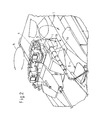
- FIG 2 shows a lifting device 1 laterally attached to the tower housing 5 of tower 4.
- the lifting device 1 has a telescopic boom 1a, which can be extended and retracted in the direction 8.
- the lifting device 1 can be rotated in the side rotation 6 with the tower 4.
- the boom 1a can be adjusted at the height of the direction of rotation 7.
- the lifting device 1 in FIG. 3 is attached to the height-adjustable housing part 9 of the weapon 11.
- the direction of rotation 7 of the lifting device 1 is carried out here by means of the height direction of the weapon leveling system.
- the lifting device 1 is adapted to a tank tower 4 in order to avoid a restriction of the working area by the tank tower and to also use the existing directional drives of the tank tower in side and occasionally also for movement and alignment 6, 7 of the lifting device.
- a three-dimensional work area required for the lifting device is realized for the directions of movement 6, 7, 8 (FIG. 3) by means of a telescopic boom 1a and by means of the directional drives of the armored turret mentioned.
- the lifting device can alternatively be attached to the tower housing 5 at a suitable point, in which case it does not represent a load on the height-adjustable mass of the weapon system (FIG. 2).
- the conceptual design of a lifting device depends on the vehicle type and requirements.
- all other technically feasible designs for realizing the linear movement 8 are also conceivable.
- the drive for this can be operated manually or operated with external power.
- the lifting device When not in use, the lifting device can either be permanently installed on the vehicle and remain in a lashing position, or it can also be dismantled with a correspondingly low weight and geometry, carried in the vehicle or stored in a suitable location. It is also conceivable to design the lifting device in such a way that it can be used for different purposes, for example with brackets of different lengths, with a slight modification.
- the interface to the tower is preferably designed so that the Lifting device can be adapted to different towers by means of a suitable flange surface.
Landscapes
- Engineering & Computer Science (AREA)
- General Engineering & Computer Science (AREA)
- Jib Cranes (AREA)
- Forklifts And Lifting Vehicles (AREA)
- Vehicle Interior And Exterior Ornaments, Soundproofing, And Insulation (AREA)
- Air Bags (AREA)
Abstract
Description
- Die Erfindung bezieht sich auf ein gepanzertes und bewaffnetes Fahrzeug, das sich aus den üblichen Teilen wie Antriebsmotor, Getrieben, Radsätzen oder Kettenlaufwerk, einem Besatzungsraum und einem Gehäuse, das alle Ein- und Anbauten aufnimmt, und einer Waffenanlage zusammensetzt.
- Von einem derartigen Fahrzeug wird häufig auch gefordert, dass es trotz seines Gewichtes luftverlastbar ist und mittels Flugzeug oder Hubschrauber transportiert werden kann. Die Forderung der Luftverlastbarkeit von Kampffahrzeugen mit einer damit verbundenen Gewichtsbeschränkung steht im Gegensatz zu der Forderung nach einem hohen ballistischen Schutzniveau, welches wiederum mit einem erhöhten Fahrzeuggewicht einhergeht. Neben einer Reduzierung des Fahrzeuggewichts ist eine systemtechnische Lösung, ein Komplettfahrzeug in Teileinheiten zu tranportieren. Dies kann zum Beispiel ein Basisfahrzeug mit einer adaptiven Zusatzpanzerung sein, welche vor einer Luftverladung vom Fahrzeug entfernt, mit einem zusätzlichen Transportmittel transportiert und am Zielort nach der Entladung wieder am Fahrzeug montiert wird. Die Zusatzpanzerungselemente werden aufgrund ihres hohen Eigengewichts entweder mittels einer externen Kraneinrichtung oder von Hand am Fahrzeug de- oder aufmontiert, sofern die Elemente in handhabbare Module unterteilt sind.
- Nach dem Stand der Technik sind verschiedene Vorschläge zum Aufbau von modularen Fahrzeugen und modularen Teilaufbauten an Fahrzeugen gemacht worden.
- In der DE 4219688 wird ein luftverlastbares Panzerfahrzeug aus einem Fahrgestell und darauf angeordneten mehreren Gehäuseteilen aufgebaut, wobei ein Gehäuseteil aus einem fahrgestellfesten Unterteil und einem beweglichen Oberteil besteht, welches bei Lufttransport vertikal eingeschoben werden kann zur Verminderung des Fahrzeugvolumens.
- In der DE 19502036 wird ein Kettenfahrzeug schnell und kostensparend an unterschiedliche Einsatzforderungen angepasst, in dem der Wannenaufbau modular gestaltet und aus mindestens zwei Modulen besteht.
- In der DE 19619865 wird ein umrüstbares militärisches Radfahrzeug mit trennbaren Modulen dargestellt, das aus einem Grundgehäuse zur Aufnahme der Fahrzeugkomponenten besteht und von einem diesel-mechanischen zu einem diesel-elektrischen Antrieb umgebaut werden kann bei Vorteilen für die Bauhöhe und Ausgestaltung des Fahrzeugs.
- Bei einer Zusatzpanzerung als Fahrzeugmodul ist für die Montage entweder ein externer Kran erforderlich oder die Schutzmodule sind in sehr viele von der Besatzung handhabbare Stücke zu unterteilen, da es ballistischen Schutz ohne entsprechendes Gewicht nicht gibt.
- Der Nachteil dieser Lösung liegt vor allem darin, daß entweder ein zusätzliches Kranfahrzeug oder ein Bergepanzer eingesetzt werden muss oder dass die Montage bei sehr vielen kleinen Schutzmodulen aufwendig und langwierig wird.
- Belässt man die Schutzmodule in ihrer konstruktiv bedingten Größe, ist ein Kampffahrzeug bei der Auf- und Abrüstung nach heutigem Stand der Technik auf ein externes Kranfahrzeug mit Hebevorrichtung angewiesen. Dabei kann es zu logistischen Engpässen kommen, da es nur eine begrenzte Anzahl Kranfahrzeuge bei der Truppe gibt für sehr viele Aufgaben. Die Auf- und Umrüstung von mehreren Fahrzeugen kann dann kaum parallel oder nur abhängig von der Anzahl der bereitstehenden Hebezeuge erfolgen.
- Werden die Schutzmodule andererseits in handliche Stücke unterteilt, so führt dies neben einem reduzierten ballistischen Schutz in den Randbereichen dieser Stücke auch zu höheren Auf- und Umrüstzeiten wegen der großen Anzahl der Module.
- Aufgabe der Erfindung ist es, ein militärisches Fahrzeug, welches vom hauptsächlichen Einsatzzweck nicht als Kranfahrzeug ausgelegt ist, unabhängig von einem zusätzlichen Kran zu machen, um verschiedenste Aufgaben, die ohne Hebezeug nicht durchführbar sind, autark zu erfüllen, bzw. Tätigkeiten, die nach heutigem Stand der Technik manuell durchgeführt werden, einfacher und / oder schneller zu gestalten.
- Diese Aufgabe wird erfindungsgemäß durch die kennzeichnenden Merkmale des Anspruchs 1 gelöst. Weitere Merkmale ergeben sich aus den Unteransprüchen.
- Erfindungsgemäß wird ein Kampffahrzeug mit einer bordeigenen integrierten Hebevorrichtung ausgestattet. Eine Aufgabe der fahrzeugintegrierten Hebevorrichtung kann die De- und Remontage von Zusatzpanzerungsmodulen sein, welche derzeit ausschliesslich mit externen Hebeeinrichtungen erfolgt. Darüberhinaus können mit der Vorrichtung allgemeine Reparatur- und Kranarbeiten ausgeführt werden.
- Die Hebeeinrichtung muss in der Lage sein, Lasten, die sich vor, hinter oder neben dem Fahrzeug befinden, an eine beliebige Position am Fahrzeug zu befördern. Eine Einschränkung des Arbeitsbereiches der Hebeeinrichtung durch einen auf dem Fahrzeug befindlichen Panzerturm lässt sich am besten durch Adaption der Hebeeinrichtung an den Panzerturm selbst verhindern. Darüberhinaus können die Richtantriebe des Turms oder der Waffe für die Bewegung der Hebeeinrichtung mitverwendet werden, was die Ausführung der Hebeeinrichtung vereinfacht. Bei einem Fahrzeug mit Turm ist die Adaption der Hebeeinrichtung an den Turm aus genannten Gründen zu bevorzugen.
- Die Vorteile der Erfindung liegen darin,
- dass Auf- und Umrüstzeiten bezüglich zum Beispiel Zusatzpanzerungsmodulen wegen des Vorhandenseins einer fahrzeugintegrierten Hebeeinrichtung minimal sind,
- dass der Rüstvorgang unabhängig vom Vorhandensein eines Unterstützungsfahrzeuges oder Kranes durchgeführt werden kann und
- dass die integrierte Hebevorrichtung auch für Reparatur- und Transportarbeiten am eigenen oder an anderen Fahrzeugen eingesetzt werden kann.
- Durch die Adaption der Hebeeinrichtung an einen vorhandenen Panzerturm wird eine Einschränkung des Arbeitsbereiches durch den Turm und auch eine mögliche Behinderung des Turms durch eine Hebeeinrichtung verhindert, sowie die Ausführung der Hebeeinrichtung vereinfacht, da erforderliche Kranbewegungen durch die Seitendrehbarkeit des Turms übernommen werden können.
- Ausführungsbeispiele der Erfindung sind in den Zeichnungen schematisch dargestellt und werden im folgenden näher beschrieben. Es zeigen:
- Figur 1:
- eine Ansicht des Fahrzeuges mit Hebeeinrichtung
- Figur 2:
- eine Detailansicht der Hebeeinrichtung am Waffenturm
- Figur 3:
- eine Alternativanordnung der Hebeeinrichtung am Waffenturm
- Figur 1 zeigt ein gepanzertes Fahrzeug 2 mit einem Turm 4 und einer Hebeeinrichtung 1 am Turm, welche ein Zusatzpanzermodul 3 am Haken 10 hat.
- Figur 2 zeigt eine Hebeeinrichtung 1 seitlich am Turmgehäuse 5 von Turm 4 angebaut. Die Hebeeinrichtung 1 besitzt einen Teleskopausleger 1a, welcher in Richtung 8 aus- und eingefahren werden kann. Die Hebeeinrichtung 1 kann in der Seitendrehung 6 mit dem Turm 4 gedreht werden. Mittels eines eigenen Drehantriebs in der Hebeeinrichtung 1 kann der Ausleger 1a in der Höhe der Drehrichtung 7 eingestellt werden.
- Alternativ ist die Hebeeinrichtung 1 in Figur 3 an dem höhenrichtbaren Gehäuseteil 9 der Waffe 11 angebaut. Die Drehrichtung 7 der Hebeeinrichtung 1 wird hierbei mittels der Höhenrichtung der Waffenrichtanlage durchgeführt.
- Die Hebeeinrichtung 1 wird an einen Panzerturm 4 adaptiert, um eine Einschränkung des Arbeitsbereiches durch den Panzerturm zu vermeiden und um die vorhandenen Richtantriebe des Panzerturms in Seite und fallweise auch Höhe auch zur Bewegung und Ausrichtung 6, 7 der Hebeeinrichtung mitzubenutzen. Ein für die Hebeeinrichtung geforderter dreidimensionaler Arbeitsbereich wird mittels eines teleskopierbaren Auslegers 1a sowie mittels der genannten Richtantriebe des Panzerturms realisiert für die Bewegungsrichtungen 6, 7, 8 (Figur 3).
- Bei Realisierung der Richtung 7 mittels eines eigenen Drehantriebs in der Hebeeinrichtung 1 kann die Hebeeinrichtung am Turmgehäuse 5 an geeigneter Stelle alternativ angebaut werden, wobei sie dann keine Belastung der höhenrichtbaren Masse der Waffenanlage darstellt (Figur 2).
- Die konzeptionelle Ausführung einer Hebeeinrichtung ist abhängig von Fahrzeugtyp und Anforderung. Neben der in der Figur dargestellten Ausführung mit einem Teleskopausleger 1a sind ebenfalls alle anderen technisch realisierbaren Ausführungen für die Realisierung der Linearbewegung 8 vorstellbar. Der Antrieb dafür kann manuell betätigt oder mit Fremdkraft betrieben sein.
- Bei Nichtgebrauch kann die Hebeeinrichtung entweder am Fahrzeug fest eingebaut und in einer Zurrposition verbleiben oder auch bei entsprechend geringem Gewicht und Geometrie abgebaut, im Fahrzeug mitgeführt oder an geeignetem Ort gelagert werden. Es ist auch vorstellbar, die Hebeeinrichtung so zu gestalten, dass diese bei geringer Modifikation für verschiedene Einsatzzwecke nutzbar ist, zum Beispiel mit Auslegern verschiedener Länge. Die Schnittstelle zum Turm wird vorzugsweise so gestaltet, dass die Hebeeinrichtung an verschiedene Türme mittels einer geeigneten Anflanschfläche adaptiert werden kann.
-
- 1
- Hebeeinrichtung
- 1a
- Teleskopausleger
- 2
- Fahrzeug
- 3
- Zusatzpanzermodul
- 4
- Turm
- 5
- Turmgehäuse
- 6
- Seitendrehrichtung
- 7
- Drehrichtung
- 8
- Richtung
- 9
- Gehäuseteil
- 10
- Haken
- 11
- Waffe
Claims (12)
- Vorrichtung mit einem Hebemittel für ein gepanzertes Fahrzeug (2) mit einem seitenrichtbaren Panzer- oder Waffenturm (4) auf dem Fahrzeug und einer höhenrichtbaren Waffe (11) im Turm sowie mit einem Radfahr- oder Kettenlaufwerk und einem Antrieb zur Fortbewegung sowie einem Fahrzeugaufbau zur Aufnahme und Einbau aller Komponenten für den Betrieb des Fahrzeugs einschliesslich einer Fahrzeugbesatzung und einer spezifischen Ausrüstung für ein Missionsfahrzeug
dadurch gekennzeichnet,
dass eine Lastenhebeeinrichtung (1) mit einem Kranausleger (1a) an einer geeigneten Flanschfläche am Turm (5) oder an dem höhenrichtbaren Gehäuseteil (9) der Waffe im Turm befestigt wird und die Hebeeinrichtung fallweise mittels eigener Linear- und / oder Drehantriebe ausgerüstet ist, um Lastenhebearbeiten an allen Stellen des Trägerfahrzeugaufbaus ausführen zu können. - Vorrichtung nach Anspruch 1
dadurch gekennzeichnet,
dass die Hebeeinrichtung (1) einen teleskopierbaren Ausleger (1a) mit einem Lastaufnahmehaken oder -geschirr (10) besitzt und der Ausleger auf eine maximale Ausfahrlänge ausgefahren sowie auf eine minimale Länge und Zurrposition eingefahren werden kann. - Vorrichtung nach einem der oben genannten Ansprüche
dadurch gekennzeichnet,
dass die Hebeeinrichtung (1) einen Arbeitsraum mit drei Koordinaten, welche mit der Seitendrehachse (6) des Turms (4) und der Höhendrehachse (7) der Waffe (11) sowie der Ausfahrachse (8) des Teleskops (1 a) gebildet werden, abdeckt. - Vorrichtung nach einem der oben genannten Ansprüche
dadurch gekennzeichnet,
dass die Hebeeinrichtung (1) neben der Waffe (11) an der höhenrichtbaren Masse (9) der Waffe angebaut wird. - Vorrichtung nach einem der oben genannten Ansprüche
dadurch gekennzeichnet,
dass die Hebeeinrichtung (1) an einer geeigneten Gehäusefläche (5) am Turm (4) befestigt ist und die Hebeeinrichtung eine eigene Höhendreheinrichtung (1b) besitzt für die Drehung um die Achse (7). - Vorrichtung nach einem der oben genannten Ansprüche
dadurch gekennzeichnet,
dass die Hebeeinrichtuhg (1) bezüglich Lastaufnahmehaken und -geschirr so ausgebildet ist, dass Panzerplatten als Schutzmodule neben dem Fahrzeug aufgenommen werden und an jede Position des äußeren Fahrzeuggehäuses zur dortigen Montage gebracht werden können. - Vorrichtung nach einem der oben genannten Ansprüche
dadurch gekennzeichnet,
dass der Kranausleger (1a) der Hebeeinrichtung (1) mittels Telekopausleger oder Stangenführung oder Robotergreifarm ausgebildet wird. - Vorrichtung nach einem der oben genannten Ansprüche
dadurch gekennzeichnet,
dass der Antrieb der Linearachse (8) manuell mittels eines Getriebes aus dem Turminnenraum oder von außen bedient oder mittels hydraulischer oder elektrischer Hilfskraftenergie ausgeführt wird. - Vorrichtung nach einem der oben genannten Ansprüche
dadurch gekennzeichnet,
dass die Hebeeinrichtung (1) bei Nichtgebrauch am Fahrzeug eingefahren oder verzurrt wird oder Teile der Einrichtung abgebaut werden, speziell außen am Turm angebaute, und diese Teile im Fahrzeug an geeigneter Stelle oder auch an anderem Ort gelagert werden. - Vorrichtung nach einem der oben genannten Ansprüche
dadurch gekennzeichnet,
dass die Schnittstelle zwischen Hebeeinrichtung und Turm so ausgebildet wird, dass die Hebeeinrichtung an verschiedene Türme an verschiedenen Fahrzeugen adaptiert und aufgerüstet werden kann. - Vorrichtung nach einem der oben genannten Ansprüche
dadurch gekennzeichnet,
dass mittels Hebeeinrichtung (1) und entsprechend eingerichteten Lasthebehaken und/oder -geschirr verschiedene Lasttransport- und Reparaturaufgaben am Fahrzeug ausgeführt werden können. - Vorrichtung nach einem der oben genannten Ansprüche
dadurch gekennzeichnet,
dass die Lasthebeeinrichtung (1) mittels verlängertem Ausleger (1a) auch für Hebeaufgaben an einem zweiten neben dem Trägerfahrzeug stehenden Fahrzeug benutzt werden kann.
Applications Claiming Priority (4)
| Application Number | Priority Date | Filing Date | Title |
|---|---|---|---|
| DE10210519 | 2002-03-09 | ||
| DE10210519 | 2002-03-09 | ||
| DE10217991A DE10217991B4 (de) | 2002-03-09 | 2002-04-12 | Turmintegrierte Lastenhebeeinrichtung für gepanzerte Fahrzeuge, insbesondere Kampffahrzeuge |
| DE10217991 | 2002-04-12 |
Publications (3)
| Publication Number | Publication Date |
|---|---|
| EP1342977A2 true EP1342977A2 (de) | 2003-09-10 |
| EP1342977A3 EP1342977A3 (de) | 2004-04-28 |
| EP1342977B1 EP1342977B1 (de) | 2009-12-02 |
Family
ID=26011058
Family Applications (1)
| Application Number | Title | Priority Date | Filing Date |
|---|---|---|---|
| EP03000856A Expired - Lifetime EP1342977B1 (de) | 2002-03-09 | 2003-01-15 | Turmintegrierte Lastenhebeeinrichtung für gepanzerte Fahrzeuge, insbesondere Kampffahrzeuge |
Country Status (2)
| Country | Link |
|---|---|
| EP (1) | EP1342977B1 (de) |
| NO (1) | NO328551B1 (de) |
Citations (1)
| Publication number | Priority date | Publication date | Assignee | Title |
|---|---|---|---|---|
| EP0244124A1 (de) | 1986-05-02 | 1987-11-04 | Vickers Public Limited Company | Panzerfahrzeug mit Kran |
Family Cites Families (3)
| Publication number | Priority date | Publication date | Assignee | Title |
|---|---|---|---|---|
| US5198608A (en) * | 1991-10-17 | 1993-03-30 | Cahill Peter J | Mine clearing rake |
| AT405267B (de) * | 1993-08-04 | 1999-06-25 | Steyr Daimler Puch Ag | Stützvorrichtung für ein bergefahrzeug |
| JP2000249497A (ja) * | 1999-02-26 | 2000-09-14 | Ishikawajima Harima Heavy Ind Co Ltd | 弾薬発射車両用揚弾装置 |
-
2003
- 2003-01-15 EP EP03000856A patent/EP1342977B1/de not_active Expired - Lifetime
- 2003-01-20 NO NO20030266A patent/NO328551B1/no not_active IP Right Cessation
Patent Citations (1)
| Publication number | Priority date | Publication date | Assignee | Title |
|---|---|---|---|---|
| EP0244124A1 (de) | 1986-05-02 | 1987-11-04 | Vickers Public Limited Company | Panzerfahrzeug mit Kran |
Non-Patent Citations (1)
| Title |
|---|
| "Jane's Combat Support Equipment", 1978, JANE'S YEARBOOKS VERLAG, pages: 7 |
Also Published As
| Publication number | Publication date |
|---|---|
| NO20030266D0 (no) | 2003-01-20 |
| NO328551B1 (no) | 2010-03-15 |
| EP1342977A3 (de) | 2004-04-28 |
| EP1342977B1 (de) | 2009-12-02 |
| NO20030266L (no) | 2003-09-10 |
Similar Documents
| Publication | Publication Date | Title |
|---|---|---|
| EP3507232B1 (de) | Turmkran | |
| WO2002101320A1 (de) | Schützenpanzer | |
| EP3297946B1 (de) | Mobile schachtwinde | |
| EP1061323A2 (de) | Gepanzertes Transportkraftfahrzeug | |
| DE102009050729A1 (de) | Mobiler Seilroboter zur Montage von Großbaugruppen | |
| DE202010003269U1 (de) | Kran | |
| DE102015016279A1 (de) | Turmdrehkran | |
| EP2243954A2 (de) | Manipulator zur Montage von Rotorblättern einer Windkraftanlage | |
| EP1342615B1 (de) | Integrierte Lastenhebeeinrichtung für gepanzerte Fahrzeuge, insbesondere Kampffahrzeuge | |
| EP1191303B1 (de) | Gepanzertes Fahrzeug, insbesondere Kampffahrzeug | |
| DE10217990B4 (de) | Lastenhebeeinrichtung für gepanzerte Fahrzeuge, insbesondere Kampffahrzeuge | |
| DE10217991B4 (de) | Turmintegrierte Lastenhebeeinrichtung für gepanzerte Fahrzeuge, insbesondere Kampffahrzeuge | |
| EP1186848B1 (de) | Kampffahrzeug mit Abschussvorrichtung für Artillerieraketen | |
| DE102012103353A1 (de) | Verfahren zum Transport eines Fahrzeugs sowie Fahrzeug | |
| EP1342977B1 (de) | Turmintegrierte Lastenhebeeinrichtung für gepanzerte Fahrzeuge, insbesondere Kampffahrzeuge | |
| DE202004001879U1 (de) | Vorrichtung für ein Fahrzeug, insbesondere gepanzertes Transportfahrzeug | |
| EP4607749A1 (de) | Mobile energieversorgungseinheit für eine mobile arbeitsmaschine | |
| EP1291609B1 (de) | Gepanzertes Transportfahrzeug mit Batterie-Schwenkmechanismus | |
| EP3129318B1 (de) | Hubvorrichtung für ein u-boot | |
| DE10133147B4 (de) | Gepanzertes Transportfahrzeug | |
| EP1291604B1 (de) | Lagerung einer Abschleppvorrichtung für ein gepanzertes Transportfahrezeug | |
| DE102019123849B4 (de) | Fahrzeugkran | |
| DE102012207150A1 (de) | Traverse | |
| DE20121851U1 (de) | Gepanzertes Transportfahrzeug mit einem Gefechtsstand | |
| DE102009060996A1 (de) | Montagefahrzeug für Solarmodule |
Legal Events
| Date | Code | Title | Description |
|---|---|---|---|
| PUAI | Public reference made under article 153(3) epc to a published international application that has entered the european phase |
Free format text: ORIGINAL CODE: 0009012 |
|
| AK | Designated contracting states |
Kind code of ref document: A2 Designated state(s): AT BE BG CH CY CZ DE DK EE ES FI FR GB GR HU IE IT LI LU MC NL PT SE SI SK TR |
|
| AX | Request for extension of the european patent |
Extension state: AL LT LV MK RO |
|
| PUAL | Search report despatched |
Free format text: ORIGINAL CODE: 0009013 |
|
| AK | Designated contracting states |
Kind code of ref document: A3 Designated state(s): AT BE BG CH CY CZ DE DK EE ES FI FR GB GR HU IE IT LI LU MC NL PT SE SI SK TR |
|
| AX | Request for extension of the european patent |
Extension state: AL LT LV MK RO |
|
| 17P | Request for examination filed |
Effective date: 20040320 |
|
| AKX | Designation fees paid |
Designated state(s): AT BE BG CH CY CZ DE DK EE ES FI FR GB GR HU IE IT LI LU MC NL PT SE SI SK TR |
|
| RAP1 | Party data changed (applicant data changed or rights of an application transferred) |
Owner name: RHEINMETALL LANDSYSTEME GMBH |
|
| 17Q | First examination report despatched |
Effective date: 20080827 |
|
| GRAP | Despatch of communication of intention to grant a patent |
Free format text: ORIGINAL CODE: EPIDOSNIGR1 |
|
| GRAS | Grant fee paid |
Free format text: ORIGINAL CODE: EPIDOSNIGR3 |
|
| GRAA | (expected) grant |
Free format text: ORIGINAL CODE: 0009210 |
|
| AK | Designated contracting states |
Kind code of ref document: B1 Designated state(s): AT BE BG CH CY CZ DE DK EE ES FI FR GB GR HU IE IT LI LU MC NL PT SE SI SK TR |
|
| REG | Reference to a national code |
Ref country code: GB Ref legal event code: FG4D Free format text: NOT ENGLISH |
|
| REG | Reference to a national code |
Ref country code: CH Ref legal event code: EP |
|
| REG | Reference to a national code |
Ref country code: IE Ref legal event code: FG4D |
|
| REF | Corresponds to: |
Ref document number: 50312167 Country of ref document: DE Date of ref document: 20100114 Kind code of ref document: P |
|
| REG | Reference to a national code |
Ref country code: SE Ref legal event code: TRGR |
|
| REG | Reference to a national code |
Ref country code: NL Ref legal event code: VDEP Effective date: 20091202 |
|
| REG | Reference to a national code |
Ref country code: ES Ref legal event code: FG2A Ref document number: 2337456 Country of ref document: ES Kind code of ref document: T3 |
|
| PG25 | Lapsed in a contracting state [announced via postgrant information from national office to epo] |
Ref country code: FI Free format text: LAPSE BECAUSE OF FAILURE TO SUBMIT A TRANSLATION OF THE DESCRIPTION OR TO PAY THE FEE WITHIN THE PRESCRIBED TIME-LIMIT Effective date: 20091202 |
|
| PG25 | Lapsed in a contracting state [announced via postgrant information from national office to epo] |
Ref country code: SI Free format text: LAPSE BECAUSE OF FAILURE TO SUBMIT A TRANSLATION OF THE DESCRIPTION OR TO PAY THE FEE WITHIN THE PRESCRIBED TIME-LIMIT Effective date: 20091202 Ref country code: CY Free format text: LAPSE BECAUSE OF FAILURE TO SUBMIT A TRANSLATION OF THE DESCRIPTION OR TO PAY THE FEE WITHIN THE PRESCRIBED TIME-LIMIT Effective date: 20091202 |
|
| REG | Reference to a national code |
Ref country code: IE Ref legal event code: FD4D |
|
| PG25 | Lapsed in a contracting state [announced via postgrant information from national office to epo] |
Ref country code: PT Free format text: LAPSE BECAUSE OF FAILURE TO SUBMIT A TRANSLATION OF THE DESCRIPTION OR TO PAY THE FEE WITHIN THE PRESCRIBED TIME-LIMIT Effective date: 20100402 Ref country code: BG Free format text: LAPSE BECAUSE OF FAILURE TO SUBMIT A TRANSLATION OF THE DESCRIPTION OR TO PAY THE FEE WITHIN THE PRESCRIBED TIME-LIMIT Effective date: 20100302 Ref country code: IE Free format text: LAPSE BECAUSE OF FAILURE TO SUBMIT A TRANSLATION OF THE DESCRIPTION OR TO PAY THE FEE WITHIN THE PRESCRIBED TIME-LIMIT Effective date: 20091202 Ref country code: NL Free format text: LAPSE BECAUSE OF FAILURE TO SUBMIT A TRANSLATION OF THE DESCRIPTION OR TO PAY THE FEE WITHIN THE PRESCRIBED TIME-LIMIT Effective date: 20091202 Ref country code: EE Free format text: LAPSE BECAUSE OF FAILURE TO SUBMIT A TRANSLATION OF THE DESCRIPTION OR TO PAY THE FEE WITHIN THE PRESCRIBED TIME-LIMIT Effective date: 20091202 |
|
| BERE | Be: lapsed |
Owner name: RHEINMETALL LANDSYSTEME G.M.B.H. Effective date: 20100131 |
|
| PG25 | Lapsed in a contracting state [announced via postgrant information from national office to epo] |
Ref country code: CZ Free format text: LAPSE BECAUSE OF FAILURE TO SUBMIT A TRANSLATION OF THE DESCRIPTION OR TO PAY THE FEE WITHIN THE PRESCRIBED TIME-LIMIT Effective date: 20091202 Ref country code: MC Free format text: LAPSE BECAUSE OF NON-PAYMENT OF DUE FEES Effective date: 20100131 Ref country code: SK Free format text: LAPSE BECAUSE OF FAILURE TO SUBMIT A TRANSLATION OF THE DESCRIPTION OR TO PAY THE FEE WITHIN THE PRESCRIBED TIME-LIMIT Effective date: 20091202 |
|
| REG | Reference to a national code |
Ref country code: CH Ref legal event code: PL |
|
| PLBE | No opposition filed within time limit |
Free format text: ORIGINAL CODE: 0009261 |
|
| STAA | Information on the status of an ep patent application or granted ep patent |
Free format text: STATUS: NO OPPOSITION FILED WITHIN TIME LIMIT |
|
| PG25 | Lapsed in a contracting state [announced via postgrant information from national office to epo] |
Ref country code: CH Free format text: LAPSE BECAUSE OF NON-PAYMENT OF DUE FEES Effective date: 20100131 Ref country code: LI Free format text: LAPSE BECAUSE OF NON-PAYMENT OF DUE FEES Effective date: 20100131 Ref country code: GR Free format text: LAPSE BECAUSE OF FAILURE TO SUBMIT A TRANSLATION OF THE DESCRIPTION OR TO PAY THE FEE WITHIN THE PRESCRIBED TIME-LIMIT Effective date: 20100303 |
|
| 26N | No opposition filed |
Effective date: 20100903 |
|
| PG25 | Lapsed in a contracting state [announced via postgrant information from national office to epo] |
Ref country code: DK Free format text: LAPSE BECAUSE OF FAILURE TO SUBMIT A TRANSLATION OF THE DESCRIPTION OR TO PAY THE FEE WITHIN THE PRESCRIBED TIME-LIMIT Effective date: 20091202 |
|
| PG25 | Lapsed in a contracting state [announced via postgrant information from national office to epo] |
Ref country code: BE Free format text: LAPSE BECAUSE OF NON-PAYMENT OF DUE FEES Effective date: 20100131 |
|
| PG25 | Lapsed in a contracting state [announced via postgrant information from national office to epo] |
Ref country code: AT Free format text: LAPSE BECAUSE OF NON-PAYMENT OF DUE FEES Effective date: 20100115 |
|
| PG25 | Lapsed in a contracting state [announced via postgrant information from national office to epo] |
Ref country code: LU Free format text: LAPSE BECAUSE OF NON-PAYMENT OF DUE FEES Effective date: 20100115 Ref country code: HU Free format text: LAPSE BECAUSE OF FAILURE TO SUBMIT A TRANSLATION OF THE DESCRIPTION OR TO PAY THE FEE WITHIN THE PRESCRIBED TIME-LIMIT Effective date: 20100603 |
|
| PG25 | Lapsed in a contracting state [announced via postgrant information from national office to epo] |
Ref country code: TR Free format text: LAPSE BECAUSE OF FAILURE TO SUBMIT A TRANSLATION OF THE DESCRIPTION OR TO PAY THE FEE WITHIN THE PRESCRIBED TIME-LIMIT Effective date: 20091202 |
|
| REG | Reference to a national code |
Ref country code: FR Ref legal event code: PLFP Year of fee payment: 14 |
|
| PGFP | Annual fee paid to national office [announced via postgrant information from national office to epo] |
Ref country code: ES Payment date: 20160112 Year of fee payment: 14 Ref country code: DE Payment date: 20160120 Year of fee payment: 14 Ref country code: IT Payment date: 20160127 Year of fee payment: 14 |
|
| PGFP | Annual fee paid to national office [announced via postgrant information from national office to epo] |
Ref country code: SE Payment date: 20160120 Year of fee payment: 14 Ref country code: GB Payment date: 20160120 Year of fee payment: 14 Ref country code: FR Payment date: 20160121 Year of fee payment: 14 |
|
| REG | Reference to a national code |
Ref country code: DE Ref legal event code: R119 Ref document number: 50312167 Country of ref document: DE |
|
| GBPC | Gb: european patent ceased through non-payment of renewal fee |
Effective date: 20170115 |
|
| REG | Reference to a national code |
Ref country code: FR Ref legal event code: ST Effective date: 20170929 |
|
| PG25 | Lapsed in a contracting state [announced via postgrant information from national office to epo] |
Ref country code: FR Free format text: LAPSE BECAUSE OF NON-PAYMENT OF DUE FEES Effective date: 20170131 |
|
| PG25 | Lapsed in a contracting state [announced via postgrant information from national office to epo] |
Ref country code: DE Free format text: LAPSE BECAUSE OF NON-PAYMENT OF DUE FEES Effective date: 20170801 Ref country code: SE Free format text: LAPSE BECAUSE OF NON-PAYMENT OF DUE FEES Effective date: 20170116 Ref country code: GB Free format text: LAPSE BECAUSE OF NON-PAYMENT OF DUE FEES Effective date: 20170115 |
|
| PG25 | Lapsed in a contracting state [announced via postgrant information from national office to epo] |
Ref country code: IT Free format text: LAPSE BECAUSE OF NON-PAYMENT OF DUE FEES Effective date: 20170115 |
|
| PG25 | Lapsed in a contracting state [announced via postgrant information from national office to epo] |
Ref country code: ES Free format text: LAPSE BECAUSE OF NON-PAYMENT OF DUE FEES Effective date: 20170116 |
|
| REG | Reference to a national code |
Ref country code: ES Ref legal event code: FD2A Effective date: 20181114 |