EP1342006B1 - Brennstoffeinspritzventil - Google Patents
Brennstoffeinspritzventil Download PDFInfo
- Publication number
- EP1342006B1 EP1342006B1 EP01993761A EP01993761A EP1342006B1 EP 1342006 B1 EP1342006 B1 EP 1342006B1 EP 01993761 A EP01993761 A EP 01993761A EP 01993761 A EP01993761 A EP 01993761A EP 1342006 B1 EP1342006 B1 EP 1342006B1
- Authority
- EP
- European Patent Office
- Prior art keywords
- fuel injection
- valve
- swirl
- injection valve
- fuel
- Prior art date
- Legal status (The legal status is an assumption and is not a legal conclusion. Google has not performed a legal analysis and makes no representation as to the accuracy of the status listed.)
- Expired - Lifetime
Links
Images


Classifications
-
- F—MECHANICAL ENGINEERING; LIGHTING; HEATING; WEAPONS; BLASTING
- F02—COMBUSTION ENGINES; HOT-GAS OR COMBUSTION-PRODUCT ENGINE PLANTS
- F02M—SUPPLYING COMBUSTION ENGINES IN GENERAL WITH COMBUSTIBLE MIXTURES OR CONSTITUENTS THEREOF
- F02M61/00—Fuel-injectors not provided for in groups F02M39/00 - F02M57/00 or F02M67/00
- F02M61/16—Details not provided for in, or of interest apart from, the apparatus of groups F02M61/02 - F02M61/14
- F02M61/162—Means to impart a whirling motion to fuel upstream or near discharging orifices
-
- F—MECHANICAL ENGINEERING; LIGHTING; HEATING; WEAPONS; BLASTING
- F02—COMBUSTION ENGINES; HOT-GAS OR COMBUSTION-PRODUCT ENGINE PLANTS
- F02M—SUPPLYING COMBUSTION ENGINES IN GENERAL WITH COMBUSTIBLE MIXTURES OR CONSTITUENTS THEREOF
- F02M51/00—Fuel-injection apparatus characterised by being operated electrically
- F02M51/06—Injectors peculiar thereto with means directly operating the valve needle
- F02M51/061—Injectors peculiar thereto with means directly operating the valve needle using electromagnetic operating means
- F02M51/0625—Injectors peculiar thereto with means directly operating the valve needle using electromagnetic operating means characterised by arrangement of mobile armatures
- F02M51/0664—Injectors peculiar thereto with means directly operating the valve needle using electromagnetic operating means characterised by arrangement of mobile armatures having a cylindrically or partly cylindrically shaped armature, e.g. entering the winding; having a plate-shaped or undulated armature entering the winding
- F02M51/0671—Injectors peculiar thereto with means directly operating the valve needle using electromagnetic operating means characterised by arrangement of mobile armatures having a cylindrically or partly cylindrically shaped armature, e.g. entering the winding; having a plate-shaped or undulated armature entering the winding the armature having an elongated valve body attached thereto
Definitions
- the invention is based on a fuel injection valve according to the preamble of the main claim, such as from the publications WO 99 00201 A and WO 00 12891 A are known.
- a disadvantage of the known from US 5,058,549 Fuel injection valve is in particular the high Production cost of both the valve closing body and / or the valve needle, which must be provided with swirl grooves, as well as the valve seat body, in which the Spray openings are formed. especially the different inclination of the ejection openings and the high Requirements for the accuracy of the diameter of the Spray openings require a complex Manufacturing process.
- a Fuel injection valve known which is a valve needle having, with its shaft in the bore of a Valve guide part is guided, when supplied by pressurized fuel via radial, in Guide part arranged and opening into the guide bore Cross holes in the flow direction of the fuel opens and set the fuel in rotation via grooves. Further has the fuel injection valve downstream of the Valve needle at least two spray openings on.
- a disadvantage of the known from DE 1 601 988 Fuel injection valve is in particular by the outward opening movement conditional disturbance of the Dralls of fuel, which mainly by the big one Dead volume one between the valve closing body and the Spray openings trained swirl chamber caused becomes.
- the swirl flow can no longer be kept homogeneous be, and the cross-section of the grooves when opening the Fuel injection valve increased so much that the Swirl flow comes to a standstill.
- the fuel injection valve according to the invention with the characterizing features of the main claim has In contrast, the advantage that the benefits of a multi-hole fuel injector with one of them Fuel injection valve with spin treatment under the most extensive use of standard components combined can be.
- a Spin device for example, a conventional Swirl disk, inlet side of a swirl chamber is arranged, which tells the fuel a twist, so that in the Swirl chamber forms a homogeneous swirl flow.
- the fuel can through several Spray orifices, for example, in one of the Multi-nozzle technology known valve seat body formed are to be hosed simultaneously.
- the formation of swirl channels in a guide extension of the valve closing body is advantageous because in addition to the spin-generating arrangement of the inflow opening also a offset-free guidance of the valve closing body is possible.
- the swirl flow in the Swirl chamber can be adjusted according to requirements.
- the embodiment of the twisting device as Swirl disk advantageous, since this easy to manufacture and easy to install.
- the illustrated in Fig. 1A first embodiment of a Fuel injection valve 1 according to the invention is in the Shape of a fuel injection valve 1 for Fuel injection systems of mixture compression, spark-ignited internal combustion engines running.
- the Fuel injector 1 is particularly suitable for direct injection of fuel into one illustrated combustion chamber of an internal combustion engine.
- the fuel injection valve 1 consists of a Nozzle body 2, in which a valve needle 3 is arranged.
- the valve needle 3 is connected to a valve closing body 4 in Operative connection, with a on a valve seat body. 5 arranged valve seat surface 6 to a sealing seat interacts.
- the nozzle body 2 is through a seal 8 against the outer pole 9 of a magnetic coil 10th sealed.
- the magnetic coil 10 is in a coil housing 11 encapsulated and wound on a bobbin 12, which rests against an inner pole 13 of the magnetic coil 10. Of the Inner pole 13 and the outer pole 9 are through a gap 26th separated and based on one Connecting component 29 from.
- the magnetic coil 10 is connected via a Line 19 of a via an electrical plug contact 17th energized electric current.
- the plug contact 17 is surrounded by a plastic sheath 18, the Inner pole 13 may be molded.
- the valve needle 3 is in a valve needle guide fourteenth guided, which is designed disk-shaped. to Stroke adjustment is a paired shim 15.
- An the other side of the dial 15 is a Anchor 20. This is about a first flange 21st non-positively connected to the valve needle 3 in conjunction, which by a weld 22 with the first flange 21 connected is.
- On the first flange 21 is supported Return spring 23 from which in the present design of Fuel injection valve 1 by a sleeve 24 Bias is brought.
- In the valve seat body 5 are Inflow openings 34 both to the fuel line as well intended for swirl processing.
- the Fuel injection valve 1 is opposed by a seal 28 a fuel supply not shown sealed.
- the armature 20 drops sufficient degradation of the magnetic field by the force of Return spring 23 from the inner pole 13, causing the with the valve needle 3 operatively connected flange 21st moved against the stroke direction.
- the valve needle 3 is thereby moved in the same direction, causing the Valve closing body 4 touches on the valve seat surface 6 and the fuel injection valve 1 is closed.
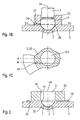
- Fig. 1B shows in an abstract, schematized Sectional view of the spray-side end of the in Fig. 1A illustrated fuel injection valve according to the invention 1.
- the detail shown in Fig. 1B is shown in Fig. 1A with IB.
- Matching components are each provided with matching reference numerals.
- Inventive fuel injection valve 1 of FIG. 1A comprises a valve seat body 5, the at least one Inflow opening 34 has, which acts as a swirl channel 37 and in a hollow cylindrical guide extension 35 is formed, which with the valve seat body 5 either integrally formed or by welding, soldering or similar method with the valve seat body 5 connected is.
- the valve needle 3 with the formed thereon Valve-closing body 4 is through the guide extension 35 for Avoidance of center offsets led to the error-free To ensure operation of the fuel injection valve 1.
- Spray openings 7 can be part of a ring-shaped arrangement of ejection openings 7 be, consisting of one or more preferably concentric rings consists.
- a spherical shell swirl chamber 36 formed, whose volume is preferably such that the dead volume is minimal and a circumferential directed swirl flow with inflow of fuel in the swirl chamber 36 can form.
- Fig. 1C shows in an excerpt, schematic Sectional view a section through that in Fig. 1B illustrated embodiment of the invention Fuel injection valve 1 along the line IC IC.
- inflow opening 34 for the sake of clarity, only an inflow opening 34 is shown. Because of However, symmetry should be at least two, more advantageous but four or more inflow openings 34 may be present to on the one hand through the fuel flowing through symmetrizing forces and on the other hand to the injected fuel cloud as well as possible to the to adapt to stoichiometric requirements.
- Fig. 2 is in the same area as in Fig. 1B, a second Embodiment of an inventively designed Fuel injection valve 1 shown.
- the second embodiment of the downstream part of the Fuel injection valve 1 composed of three components, which are manufactured individually and then assembled.
- a swirl disk 39 is arranged, the at least one, advantageously more than two Swirl channels 40 has.
- the offset-free guidance of Valve needle 3 and the valve closing body 4 is in present embodiment by a guide element 38 guaranteed.
- the guide member 38 and the Swirl disk 39 each have a recess 41, 42 on, which are penetrated by the valve needle 3.
- the Guide member 38 and the swirl disk 39 can for example, by soldering, welding, gluing or others connecting procedures with each other as well as with the Valve seat body 5 to be connected.
- a swirl chamber 36 is formed, which for the Homogenization of the swirl flow ensures that by the Swirl disk 39 flowing through the fuel in the Swirl chamber 36 is caused.
- FIGS. 3A to 3C show schematic spray patterns of various fuel injection valves 1 with and without swirl treatment and with one or more injection orifices 7.
- FIGS. 3A to 3C each show FIG. 4 in which the lift throttling coefficients of the differently configured fuel injection valves 1 in FIG Dependence on the stroke of the valve needle are shown.
- the stroke throttling coefficient dQ stat / dh defines the change of the static flow Q stat with the stroke h of the valve needle 3.
- Fig. 3A illustrates the jet image of a Fuel injection valve 1 with conventional Spin preparation, for example with a swirl disk 39, and only one spray opening 7.
- Twist processing shows a relatively homogeneous Mixture cloud 43, which, however, due to the shape of the Spray opening 7 opens relatively wide and thus no deep Penetration of the combustion chamber achieved. Modifications in the Shape of the injection opening 7 are not satisfactory at the representation of the mixture cloud 43, since throttling effects and turbulences disturbing, which is why the Penetration of the combustion chamber by a no further reducible spray opening 7 is limited.
- the curve A in FIG. 4 belonging to FIG. 3A is rhombic characterized.
- the Hubdrosselungskostory is for that with conventional spin conditioning and only one Spray opening 7 equipped fuel injection valve. 1 constant over the stroke of the valve needle 3 about 0.01% / ⁇ m.
- Fig. 3B shows in comparison the jet image of a Fuel injection valve 1 without spin conditioning, the however, with several ejection openings 7 according to known Multi-hole concepts is provided.
- Fig. 4 is the belonging to Fig. 3B curve B with triangles characterized.
- the Hubdrosselungskosuper is for a equipped with several ejection openings 7
- Fuel injection valve 1 according to known multi-hole concepts about 0.1% / ⁇ m, which is about ten times the value shown in Fig. 3A shown fuel injector 1 with Twist processing corresponds.
- the static Fuel flow through the fuel injection valve 1 strongly depends on the stroke of the valve needle 3, whereby large Scatters in the injection quantities can occur.
- Fig. 3C the jet image of one according to the invention designed fuel injection valve 1 with Twist processing and several ejection openings 7 shown.
- the curve C in FIG. 4 corresponds to that in FIG. 3C illustrated beam distribution.
- the inventively designed fuel injector 1 thus has a high penetration depth of the mixture cloud 43 in the combustion chamber and a low dependence of the static flow from the stroke of the valve needle 3 and Accordingly, only a slight scatter of the static flow on.
- the invention is not limited to those shown Embodiments limited and z. B. also for Fuel injection valves 1 with other arrangements of spin-processing devices, with more or less Inlet openings 34 or swirl disks with more or less Swirl channels 40 and for any types of Fuel injectors 1 applicable.
Landscapes
- Engineering & Computer Science (AREA)
- Chemical & Material Sciences (AREA)
- Combustion & Propulsion (AREA)
- Mechanical Engineering (AREA)
- General Engineering & Computer Science (AREA)
- Physics & Mathematics (AREA)
- Electromagnetism (AREA)
- Fuel-Injection Apparatus (AREA)
Description
- Fig. 1A
- einen schematischen Schnitt durch ein erstes Ausführungsbeispiel eines erfindungsgemäßen Brennstoffeinspritzventils,
- Fig. 1B
- einen schematischen Teilschnitt durch das in Fig. 1 dargestellte erste Ausführungsbeispiel eines erfindungsgemäßen Brennstoffeinspritzventils im Bereich IB in Fig. 1A,
- Fig. 1C
- einen schematischen Schnitt entlang der in Fig. 1B mit IC-IC bezeichneten Linie,
- Fig. 2
- einen schematischen Teilschnitt durch ein zweites Ausführungsbeispiel eines erfindungsgemäßen Brennstoffeinspritzventils im gleichen Bereich wie Fig. 1B,
- Fig. 3A-C
- Strahlbilder eines herkömmlichen Brennstoffeinspritzventils mit Drallaufbereitung sowie eines Brennstoffeinspritzventils mit Mehrlochdüse ohne und mit Drallaufbereitung, und
- Fig. 4
- ein Diagramm des statischen Durchflusses in Abhängigkeit vom Hub der Ventilnadel für die in Fig. 3A-3C dargestellten Strahlbilder von Brennstoffeinspritzventilen.
Claims (7)
- Brennstoffeinspritzventil (1), insbesondere zum direkten Einspritzen von Brennstoff in einen Brennraum einer Brennkraftmaschine, mit einer Ventilnadel (3), die an ihrem abspritzseitigen Ende einen Ventilschließkörper (4) aufweist, der mit einer Ventilsitzfläche (6), die an einem Ventilsitzkörper (5) ausgebildet ist, zu einem Dichtsitz zusammenwirkt, zumindest einem Drallkanal (37, 40), einer an dem Ventilsitzkörper (5) ausgebildeten Drallkammer (36) und mehreren aus der Drallkammer (36) ausmündenden Abspritzöffnungen (7), durch die der mit einem Drall versehene Brennstoff gleichzeitig abgespritzt wird, wobei der zumindest eine Drallkanal (37, 40) in dem Ventilsitzkörper (5) oder in einer dem Ventilsitzkörper (5) benachbarten Drallscheibe (39) ausgebildet ist,
dadurch gekennzeichnet, daß die Drallkammer (36) kugelschalenförmig ausgebildet ist. - Brennstoffeinspritzventil nach Anspruch 1,
dadurch gekennzeichnet, daß der Drallkanal (37; 40) zulaufseitig des Dichtsitzes angeordnet ist. - Brennstoffeinspritzventil nach Anspruch 1 oder 2,
dadurch gekennzeichnet, daß der Drallkanal (37; 40) durch Zuströmöffnungen (34) gebildet ist, die in einem Führungsfortsatz (35) des Ventilsitzkörpers (5) ausgebildet sind. - Brennstoffeinspritzventil nach Anspruch 3,
dadurch gekennzeichnet, daß der Führungsfortsatz (35) mit dem Ventilsitzkörper (5) entweder einstückig ausgebildet ist oder mit dem Ventilsitzkörper (5) verschweißt, verlötet oder verklebt ist. - Brennstoffeinspritzventil nach Anspruch 3 oder 4,
dadurch gekennzeichnet, daß die Zuströmöffnungen (34) eine tangentiale Komponente gegenüber einer Längsachse (44) des Brennstoffeinspritzventils (1) aufweisen. - Brennstoffeinspritzventil nach Anspruch 1 oder 2,
dadurch gekennzeichnet, daß die Drallscheibe (39) zwischen einem Führungselement (38) und dem Ventilsitzkörper (5) angeordnet ist. - Brennstoffeinspritzventil nach Anspruch 6,
dadurch gekennzeichnet, daß die Ventilnadel (3) und/oder der Ventilschließkörper (4) das Führungselement (38) und die Drallscheibe (39) durch Ausnehmungen (42, 41) durchgreifen.
Applications Claiming Priority (3)
| Application Number | Priority Date | Filing Date | Title |
|---|---|---|---|
| DE10055513A DE10055513B4 (de) | 2000-11-09 | 2000-11-09 | Brennstoffeinspritzventil |
| DE10055513 | 2000-11-09 | ||
| PCT/DE2001/004188 WO2002038946A1 (de) | 2000-11-09 | 2001-11-09 | Brennstoffeinspritzventil |
Publications (2)
| Publication Number | Publication Date |
|---|---|
| EP1342006A1 EP1342006A1 (de) | 2003-09-10 |
| EP1342006B1 true EP1342006B1 (de) | 2005-02-23 |
Family
ID=7662679
Family Applications (1)
| Application Number | Title | Priority Date | Filing Date |
|---|---|---|---|
| EP01993761A Expired - Lifetime EP1342006B1 (de) | 2000-11-09 | 2001-11-09 | Brennstoffeinspritzventil |
Country Status (5)
| Country | Link |
|---|---|
| US (1) | US6966504B2 (de) |
| EP (1) | EP1342006B1 (de) |
| JP (1) | JP2004513295A (de) |
| DE (2) | DE10055513B4 (de) |
| WO (1) | WO2002038946A1 (de) |
Families Citing this family (7)
| Publication number | Priority date | Publication date | Assignee | Title |
|---|---|---|---|---|
| ITBO20040560A1 (it) | 2004-09-10 | 2004-12-10 | Magneti Marelli Powertrain Spa | Iniettore di carburante con valvola di iniezione provvista di alimentazione laterale |
| WO2007013165A1 (ja) * | 2005-07-29 | 2007-02-01 | Mitsubishi Denki Kabushiki Kaisha | 燃料噴射弁 |
| KR100933407B1 (ko) * | 2007-03-27 | 2009-12-24 | 미쓰비시덴키 가부시키가이샤 | 연료 분사 밸브 |
| EP2700808A1 (de) * | 2012-08-23 | 2014-02-26 | Continental Automotive GmbH | Sitzplatte und Ventilanordnung für ein Einspritzventil |
| WO2017099714A1 (en) * | 2015-12-07 | 2017-06-15 | Cummins Inc. | Spherical sac within fuel injector nozzle |
| DE102018218678A1 (de) | 2018-10-31 | 2020-04-30 | Robert Bosch Gmbh | Ventil zum Zumessen eines Fluids, insbesondere Brennstoffeinspritzventil |
| DE102018221086A1 (de) | 2018-12-06 | 2020-06-10 | Robert Bosch Gmbh | Ventil zum Zumessen eines Fluids, insbesondere Brennstoffeinspritzventil |
Family Cites Families (18)
| Publication number | Priority date | Publication date | Assignee | Title |
|---|---|---|---|---|
| DE1601988C3 (de) * | 1968-03-07 | 1974-01-10 | Clayton Dewandre Holdings Ltd., London | Kraftstoffeinspritzventil für Brennkraftmaschinen |
| DE3602956A1 (de) * | 1986-01-31 | 1987-08-06 | Vdo Schindling | Elektromagnetisch betaetigbares kraftstoffeinspritzventil |
| US5058549A (en) * | 1988-02-26 | 1991-10-22 | Toyota Jidosha Kabushiki Kaisha | Fuel swirl generation type fuel injection valve and direct fuel injection type spark ignition internal combustion engine |
| DE3943005A1 (de) * | 1988-12-28 | 1990-07-05 | Hitachi Ltd | Elektromagnetische einspritzventilvorrichtung |
| JP2628742B2 (ja) * | 1989-03-10 | 1997-07-09 | 株式会社日立製作所 | 電磁式燃料噴射弁 |
| US4971254A (en) * | 1989-11-28 | 1990-11-20 | Siemens-Bendix Automotive Electronics L.P. | Thin orifice swirl injector nozzle |
| DE3940585A1 (de) | 1989-12-08 | 1991-06-13 | Bosch Gmbh Robert | Elektromagnetisch betaetigbares kraftstoffeinspritzventil |
| JP2819702B2 (ja) * | 1989-12-12 | 1998-11-05 | 株式会社デンソー | 燃料噴射弁 |
| DE4018256A1 (de) * | 1990-06-07 | 1991-12-12 | Bosch Gmbh Robert | Elektromagnetisch betaetigbares brennstoffeinspritzventil |
| DE4445358A1 (de) * | 1994-12-20 | 1996-06-27 | Bosch Gmbh Robert | Ventil und Verfahren zur Herstellung eines Ventiles |
| US6125818A (en) * | 1997-03-19 | 2000-10-03 | Hiatchi, Ltd. | Fuel injector and internal combustion engine having the same |
| JPH10281039A (ja) * | 1997-04-02 | 1998-10-20 | Hitachi Ltd | 燃料噴射装置とその制御方法 |
| DE19726991A1 (de) * | 1997-06-25 | 1999-01-07 | Bosch Gmbh Robert | Ventil und Verfahren zur Herstellung eines Ventilsitzes für ein Ventil |
| DE19736682A1 (de) * | 1997-08-22 | 1999-02-25 | Bosch Gmbh Robert | Brennstoffeinspritzventil |
| EP1049871B1 (de) * | 1998-08-27 | 2003-07-30 | Robert Bosch Gmbh | Brennstoffeinspritzventil |
| DE19907860A1 (de) * | 1998-08-27 | 2000-03-02 | Bosch Gmbh Robert | Brennstoffeinspritzventil |
| JP2001082283A (ja) * | 1999-09-20 | 2001-03-27 | Hitachi Ltd | 電磁式燃料噴射弁 |
| US6405945B1 (en) * | 2000-09-06 | 2002-06-18 | Visteon Global Tech., Inc. | Nozzle for a fuel injector |
-
2000
- 2000-11-09 DE DE10055513A patent/DE10055513B4/de not_active Expired - Fee Related
-
2001
- 2001-11-09 JP JP2002541243A patent/JP2004513295A/ja not_active Withdrawn
- 2001-11-09 WO PCT/DE2001/004188 patent/WO2002038946A1/de active IP Right Grant
- 2001-11-09 DE DE50105435T patent/DE50105435D1/de not_active Expired - Lifetime
- 2001-11-09 US US10/169,858 patent/US6966504B2/en not_active Expired - Fee Related
- 2001-11-09 EP EP01993761A patent/EP1342006B1/de not_active Expired - Lifetime
Also Published As
| Publication number | Publication date |
|---|---|
| EP1342006A1 (de) | 2003-09-10 |
| DE10055513A1 (de) | 2002-05-23 |
| DE10055513B4 (de) | 2006-03-09 |
| WO2002038946A1 (de) | 2002-05-16 |
| JP2004513295A (ja) | 2004-04-30 |
| US20040055566A1 (en) | 2004-03-25 |
| DE50105435D1 (de) | 2005-03-31 |
| US6966504B2 (en) | 2005-11-22 |
Similar Documents
| Publication | Publication Date | Title |
|---|---|---|
| WO2002029242A2 (de) | Brennstoffeinspritzventil | |
| EP1309793A1 (de) | Brennstoffeinspritzventil | |
| DE102006051327A1 (de) | Brennstoffeinspritzventil | |
| EP1307648A1 (de) | Brennstoffeinspritzventil | |
| DE4408875A1 (de) | Brennstoffeinspritzventil | |
| EP1342006B1 (de) | Brennstoffeinspritzventil | |
| EP1322858A1 (de) | Brennstoffeinspritzventil | |
| DE10061571A1 (de) | Brennstoffeinspritzventil | |
| DE10156020A1 (de) | Brennstoffeinspritzventil | |
| EP1328723B1 (de) | Brennstoffeinspritzventil | |
| DE10050751A1 (de) | Brennstoffeinspritzventil | |
| WO2002031343A2 (de) | Brennstoffeinspritzventil | |
| DE10123859A1 (de) | Brennstoffeinspritzventil | |
| DE10050752B4 (de) | Brennstoffeinspritzventil mit einem drallerzeugenden Element | |
| EP1328721B1 (de) | Brennstoffeinspritzventil | |
| DE10049519B4 (de) | Brennstoffeinspritzventil | |
| EP1197652B1 (de) | Brennstoffeinspritzventil | |
| DE10051900A1 (de) | Brennstoffeinspritzventil | |
| DE10055484B4 (de) | Brennstoffeinspritzventil | |
| DE10051896A1 (de) | Brennstoffeinspritzventil | |
| DE10061572A1 (de) | Brennstoffeinspritzventil | |
| EP1197651A2 (de) | Brennstoffeinspritzventil | |
| DE10153627A1 (de) | Brennstoffeinspritzventil |
Legal Events
| Date | Code | Title | Description |
|---|---|---|---|
| PUAI | Public reference made under article 153(3) epc to a published international application that has entered the european phase |
Free format text: ORIGINAL CODE: 0009012 |
|
| 17P | Request for examination filed |
Effective date: 20030610 |
|
| AK | Designated contracting states |
Kind code of ref document: A1 Designated state(s): AT BE CH CY DE DK ES FI FR GB GR IE IT LI LU MC NL PT SE TR |
|
| RIN1 | Information on inventor provided before grant (corrected) |
Inventor name: KEIM, NORBERT Inventor name: STIER, HUBERT |
|
| 17Q | First examination report despatched |
Effective date: 20031118 |
|
| RBV | Designated contracting states (corrected) |
Designated state(s): DE FR GB IT |
|
| GRAP | Despatch of communication of intention to grant a patent |
Free format text: ORIGINAL CODE: EPIDOSNIGR1 |
|
| GRAS | Grant fee paid |
Free format text: ORIGINAL CODE: EPIDOSNIGR3 |
|
| GRAA | (expected) grant |
Free format text: ORIGINAL CODE: 0009210 |
|
| AK | Designated contracting states |
Kind code of ref document: B1 Designated state(s): DE FR GB IT |
|
| REG | Reference to a national code |
Ref country code: GB Ref legal event code: FG4D Free format text: NOT ENGLISH |
|
| REG | Reference to a national code |
Ref country code: IE Ref legal event code: FG4D Free format text: GERMAN |
|
| REF | Corresponds to: |
Ref document number: 50105435 Country of ref document: DE Date of ref document: 20050331 Kind code of ref document: P |
|
| GBT | Gb: translation of ep patent filed (gb section 77(6)(a)/1977) |
Effective date: 20050616 |
|
| ET | Fr: translation filed | ||
| PLBE | No opposition filed within time limit |
Free format text: ORIGINAL CODE: 0009261 |
|
| STAA | Information on the status of an ep patent application or granted ep patent |
Free format text: STATUS: NO OPPOSITION FILED WITHIN TIME LIMIT |
|
| 26N | No opposition filed |
Effective date: 20051124 |
|
| PGFP | Annual fee paid to national office [announced via postgrant information from national office to epo] |
Ref country code: FR Payment date: 20061117 Year of fee payment: 6 |
|
| PGFP | Annual fee paid to national office [announced via postgrant information from national office to epo] |
Ref country code: GB Payment date: 20061123 Year of fee payment: 6 |
|
| PGFP | Annual fee paid to national office [announced via postgrant information from national office to epo] |
Ref country code: IT Payment date: 20071129 Year of fee payment: 7 |
|
| GBPC | Gb: european patent ceased through non-payment of renewal fee |
Effective date: 20071109 |
|
| REG | Reference to a national code |
Ref country code: FR Ref legal event code: ST Effective date: 20080930 |
|
| PG25 | Lapsed in a contracting state [announced via postgrant information from national office to epo] |
Ref country code: GB Free format text: LAPSE BECAUSE OF NON-PAYMENT OF DUE FEES Effective date: 20071109 |
|
| PG25 | Lapsed in a contracting state [announced via postgrant information from national office to epo] |
Ref country code: FR Free format text: LAPSE BECAUSE OF NON-PAYMENT OF DUE FEES Effective date: 20071130 |
|
| PG25 | Lapsed in a contracting state [announced via postgrant information from national office to epo] |
Ref country code: IT Free format text: LAPSE BECAUSE OF NON-PAYMENT OF DUE FEES Effective date: 20081109 |
|
| PGFP | Annual fee paid to national office [announced via postgrant information from national office to epo] |
Ref country code: DE Payment date: 20170126 Year of fee payment: 16 |
|
| REG | Reference to a national code |
Ref country code: DE Ref legal event code: R119 Ref document number: 50105435 Country of ref document: DE |
|
| PG25 | Lapsed in a contracting state [announced via postgrant information from national office to epo] |
Ref country code: DE Free format text: LAPSE BECAUSE OF NON-PAYMENT OF DUE FEES Effective date: 20180602 |