EP1342006B1 - Fuel injection valve - Google Patents
Fuel injection valve Download PDFInfo
- Publication number
- EP1342006B1 EP1342006B1 EP01993761A EP01993761A EP1342006B1 EP 1342006 B1 EP1342006 B1 EP 1342006B1 EP 01993761 A EP01993761 A EP 01993761A EP 01993761 A EP01993761 A EP 01993761A EP 1342006 B1 EP1342006 B1 EP 1342006B1
- Authority
- EP
- European Patent Office
- Prior art keywords
- fuel injection
- valve
- swirl
- injection valve
- fuel
- Prior art date
- Legal status (The legal status is an assumption and is not a legal conclusion. Google has not performed a legal analysis and makes no representation as to the accuracy of the status listed.)
- Expired - Lifetime
Links
Images


Classifications
-
- F—MECHANICAL ENGINEERING; LIGHTING; HEATING; WEAPONS; BLASTING
- F02—COMBUSTION ENGINES; HOT-GAS OR COMBUSTION-PRODUCT ENGINE PLANTS
- F02M—SUPPLYING COMBUSTION ENGINES IN GENERAL WITH COMBUSTIBLE MIXTURES OR CONSTITUENTS THEREOF
- F02M61/00—Fuel-injectors not provided for in groups F02M39/00 - F02M57/00 or F02M67/00
- F02M61/16—Details not provided for in, or of interest apart from, the apparatus of groups F02M61/02 - F02M61/14
- F02M61/162—Means to impart a whirling motion to fuel upstream or near discharging orifices
-
- F—MECHANICAL ENGINEERING; LIGHTING; HEATING; WEAPONS; BLASTING
- F02—COMBUSTION ENGINES; HOT-GAS OR COMBUSTION-PRODUCT ENGINE PLANTS
- F02M—SUPPLYING COMBUSTION ENGINES IN GENERAL WITH COMBUSTIBLE MIXTURES OR CONSTITUENTS THEREOF
- F02M51/00—Fuel-injection apparatus characterised by being operated electrically
- F02M51/06—Injectors peculiar thereto with means directly operating the valve needle
- F02M51/061—Injectors peculiar thereto with means directly operating the valve needle using electromagnetic operating means
- F02M51/0625—Injectors peculiar thereto with means directly operating the valve needle using electromagnetic operating means characterised by arrangement of mobile armatures
- F02M51/0664—Injectors peculiar thereto with means directly operating the valve needle using electromagnetic operating means characterised by arrangement of mobile armatures having a cylindrically or partly cylindrically shaped armature, e.g. entering the winding; having a plate-shaped or undulated armature entering the winding
- F02M51/0671—Injectors peculiar thereto with means directly operating the valve needle using electromagnetic operating means characterised by arrangement of mobile armatures having a cylindrically or partly cylindrically shaped armature, e.g. entering the winding; having a plate-shaped or undulated armature entering the winding the armature having an elongated valve body attached thereto
Definitions
- the invention is based on a fuel injection valve according to the preamble of the main claim, such as from the publications WO 99 00201 A and WO 00 12891 A are known.
- a disadvantage of the known from US 5,058,549 Fuel injection valve is in particular the high Production cost of both the valve closing body and / or the valve needle, which must be provided with swirl grooves, as well as the valve seat body, in which the Spray openings are formed. especially the different inclination of the ejection openings and the high Requirements for the accuracy of the diameter of the Spray openings require a complex Manufacturing process.
- a Fuel injection valve known which is a valve needle having, with its shaft in the bore of a Valve guide part is guided, when supplied by pressurized fuel via radial, in Guide part arranged and opening into the guide bore Cross holes in the flow direction of the fuel opens and set the fuel in rotation via grooves. Further has the fuel injection valve downstream of the Valve needle at least two spray openings on.
- a disadvantage of the known from DE 1 601 988 Fuel injection valve is in particular by the outward opening movement conditional disturbance of the Dralls of fuel, which mainly by the big one Dead volume one between the valve closing body and the Spray openings trained swirl chamber caused becomes.
- the swirl flow can no longer be kept homogeneous be, and the cross-section of the grooves when opening the Fuel injection valve increased so much that the Swirl flow comes to a standstill.
- the fuel injection valve according to the invention with the characterizing features of the main claim has In contrast, the advantage that the benefits of a multi-hole fuel injector with one of them Fuel injection valve with spin treatment under the most extensive use of standard components combined can be.
- a Spin device for example, a conventional Swirl disk, inlet side of a swirl chamber is arranged, which tells the fuel a twist, so that in the Swirl chamber forms a homogeneous swirl flow.
- the fuel can through several Spray orifices, for example, in one of the Multi-nozzle technology known valve seat body formed are to be hosed simultaneously.
- the formation of swirl channels in a guide extension of the valve closing body is advantageous because in addition to the spin-generating arrangement of the inflow opening also a offset-free guidance of the valve closing body is possible.
- the swirl flow in the Swirl chamber can be adjusted according to requirements.
- the embodiment of the twisting device as Swirl disk advantageous, since this easy to manufacture and easy to install.
- the illustrated in Fig. 1A first embodiment of a Fuel injection valve 1 according to the invention is in the Shape of a fuel injection valve 1 for Fuel injection systems of mixture compression, spark-ignited internal combustion engines running.
- the Fuel injector 1 is particularly suitable for direct injection of fuel into one illustrated combustion chamber of an internal combustion engine.
- the fuel injection valve 1 consists of a Nozzle body 2, in which a valve needle 3 is arranged.
- the valve needle 3 is connected to a valve closing body 4 in Operative connection, with a on a valve seat body. 5 arranged valve seat surface 6 to a sealing seat interacts.
- the nozzle body 2 is through a seal 8 against the outer pole 9 of a magnetic coil 10th sealed.
- the magnetic coil 10 is in a coil housing 11 encapsulated and wound on a bobbin 12, which rests against an inner pole 13 of the magnetic coil 10. Of the Inner pole 13 and the outer pole 9 are through a gap 26th separated and based on one Connecting component 29 from.
- the magnetic coil 10 is connected via a Line 19 of a via an electrical plug contact 17th energized electric current.
- the plug contact 17 is surrounded by a plastic sheath 18, the Inner pole 13 may be molded.
- the valve needle 3 is in a valve needle guide fourteenth guided, which is designed disk-shaped. to Stroke adjustment is a paired shim 15.
- An the other side of the dial 15 is a Anchor 20. This is about a first flange 21st non-positively connected to the valve needle 3 in conjunction, which by a weld 22 with the first flange 21 connected is.
- On the first flange 21 is supported Return spring 23 from which in the present design of Fuel injection valve 1 by a sleeve 24 Bias is brought.
- In the valve seat body 5 are Inflow openings 34 both to the fuel line as well intended for swirl processing.
- the Fuel injection valve 1 is opposed by a seal 28 a fuel supply not shown sealed.
- the armature 20 drops sufficient degradation of the magnetic field by the force of Return spring 23 from the inner pole 13, causing the with the valve needle 3 operatively connected flange 21st moved against the stroke direction.
- the valve needle 3 is thereby moved in the same direction, causing the Valve closing body 4 touches on the valve seat surface 6 and the fuel injection valve 1 is closed.
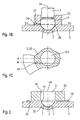
- Fig. 1B shows in an abstract, schematized Sectional view of the spray-side end of the in Fig. 1A illustrated fuel injection valve according to the invention 1.
- the detail shown in Fig. 1B is shown in Fig. 1A with IB.
- Matching components are each provided with matching reference numerals.
- Inventive fuel injection valve 1 of FIG. 1A comprises a valve seat body 5, the at least one Inflow opening 34 has, which acts as a swirl channel 37 and in a hollow cylindrical guide extension 35 is formed, which with the valve seat body 5 either integrally formed or by welding, soldering or similar method with the valve seat body 5 connected is.
- the valve needle 3 with the formed thereon Valve-closing body 4 is through the guide extension 35 for Avoidance of center offsets led to the error-free To ensure operation of the fuel injection valve 1.
- Spray openings 7 can be part of a ring-shaped arrangement of ejection openings 7 be, consisting of one or more preferably concentric rings consists.
- a spherical shell swirl chamber 36 formed, whose volume is preferably such that the dead volume is minimal and a circumferential directed swirl flow with inflow of fuel in the swirl chamber 36 can form.
- Fig. 1C shows in an excerpt, schematic Sectional view a section through that in Fig. 1B illustrated embodiment of the invention Fuel injection valve 1 along the line IC IC.
- inflow opening 34 for the sake of clarity, only an inflow opening 34 is shown. Because of However, symmetry should be at least two, more advantageous but four or more inflow openings 34 may be present to on the one hand through the fuel flowing through symmetrizing forces and on the other hand to the injected fuel cloud as well as possible to the to adapt to stoichiometric requirements.
- Fig. 2 is in the same area as in Fig. 1B, a second Embodiment of an inventively designed Fuel injection valve 1 shown.
- the second embodiment of the downstream part of the Fuel injection valve 1 composed of three components, which are manufactured individually and then assembled.
- a swirl disk 39 is arranged, the at least one, advantageously more than two Swirl channels 40 has.
- the offset-free guidance of Valve needle 3 and the valve closing body 4 is in present embodiment by a guide element 38 guaranteed.
- the guide member 38 and the Swirl disk 39 each have a recess 41, 42 on, which are penetrated by the valve needle 3.
- the Guide member 38 and the swirl disk 39 can for example, by soldering, welding, gluing or others connecting procedures with each other as well as with the Valve seat body 5 to be connected.
- a swirl chamber 36 is formed, which for the Homogenization of the swirl flow ensures that by the Swirl disk 39 flowing through the fuel in the Swirl chamber 36 is caused.
- FIGS. 3A to 3C show schematic spray patterns of various fuel injection valves 1 with and without swirl treatment and with one or more injection orifices 7.
- FIGS. 3A to 3C each show FIG. 4 in which the lift throttling coefficients of the differently configured fuel injection valves 1 in FIG Dependence on the stroke of the valve needle are shown.
- the stroke throttling coefficient dQ stat / dh defines the change of the static flow Q stat with the stroke h of the valve needle 3.
- Fig. 3A illustrates the jet image of a Fuel injection valve 1 with conventional Spin preparation, for example with a swirl disk 39, and only one spray opening 7.
- Twist processing shows a relatively homogeneous Mixture cloud 43, which, however, due to the shape of the Spray opening 7 opens relatively wide and thus no deep Penetration of the combustion chamber achieved. Modifications in the Shape of the injection opening 7 are not satisfactory at the representation of the mixture cloud 43, since throttling effects and turbulences disturbing, which is why the Penetration of the combustion chamber by a no further reducible spray opening 7 is limited.
- the curve A in FIG. 4 belonging to FIG. 3A is rhombic characterized.
- the Hubdrosselungskostory is for that with conventional spin conditioning and only one Spray opening 7 equipped fuel injection valve. 1 constant over the stroke of the valve needle 3 about 0.01% / ⁇ m.
- Fig. 3B shows in comparison the jet image of a Fuel injection valve 1 without spin conditioning, the however, with several ejection openings 7 according to known Multi-hole concepts is provided.
- Fig. 4 is the belonging to Fig. 3B curve B with triangles characterized.
- the Hubdrosselungskosuper is for a equipped with several ejection openings 7
- Fuel injection valve 1 according to known multi-hole concepts about 0.1% / ⁇ m, which is about ten times the value shown in Fig. 3A shown fuel injector 1 with Twist processing corresponds.
- the static Fuel flow through the fuel injection valve 1 strongly depends on the stroke of the valve needle 3, whereby large Scatters in the injection quantities can occur.
- Fig. 3C the jet image of one according to the invention designed fuel injection valve 1 with Twist processing and several ejection openings 7 shown.
- the curve C in FIG. 4 corresponds to that in FIG. 3C illustrated beam distribution.
- the inventively designed fuel injector 1 thus has a high penetration depth of the mixture cloud 43 in the combustion chamber and a low dependence of the static flow from the stroke of the valve needle 3 and Accordingly, only a slight scatter of the static flow on.
- the invention is not limited to those shown Embodiments limited and z. B. also for Fuel injection valves 1 with other arrangements of spin-processing devices, with more or less Inlet openings 34 or swirl disks with more or less Swirl channels 40 and for any types of Fuel injectors 1 applicable.
Description
Die Erfindung geht aus von einem Brennstoffeinspritzventil nach der Gattung des Hauptanspruchs, wie beispielsweise aus den Druckschriften WO 99 00201 A und WO 00 12891 A bekannt.The invention is based on a fuel injection valve according to the preamble of the main claim, such as from the publications WO 99 00201 A and WO 00 12891 A are known.
Aus der US 5,058,549 ist ein Brennstoffeinspritzventil bekannt, welches eine Vorrichtung zur Drallerzeugung sowie eine Hauptabspritzöffnung großen Durchmessers und eine Nebenabspritzöffnung geringeren Durchmessers aufweist. Die Neigung der Abspritzöffnungen gegenüber einer Längsachse des Brennstoffeinspritzventils ist unterschiedlich, so daß der Brennstoff unter hohem Drall und großer Penetrationslänge durch die Nebenabspritzöffnung und unter geringem Drall und großem Öffnungswinkel durch die Hauptabspritzöffnung abgespritzt wird.From US 5,058,549 is a fuel injector known which a device for swirl generation as well a main large diameter discharge hole and one Nebenabspritzöffnung has smaller diameter. The Inclination of the injection openings with respect to a longitudinal axis of the Fuel injection valve is different, so that the Fuel with high swirl and large penetration length through the Nebenabspritzöffnung and with low swirl and large opening angle through the main ejection opening is hosed.
Nachteilig an dem aus der US 5,058, 549 bekannten Brennstoffeinspritzventil ist insbesondere der hohe Fertigungsaufwand sowohl des Ventilschließkörpers und/oder der Ventilnadel, die mit Drallnuten versehen werden müssen, als auch des Ventilsitzkörpers, in welchem die Abspritzöffnungen ausgebildet sind. Insbesondere die unterschiedliche Neigung der Abspritzöffnungen und die hohen Anforderungen an die Genauigkeit der Durchmesser der Abspritzöffnungen erfordern einen aufwendigen Fertigungsprozeß.A disadvantage of the known from US 5,058,549 Fuel injection valve is in particular the high Production cost of both the valve closing body and / or the valve needle, which must be provided with swirl grooves, as well as the valve seat body, in which the Spray openings are formed. especially the different inclination of the ejection openings and the high Requirements for the accuracy of the diameter of the Spray openings require a complex Manufacturing process.
Ferner ist aus der Patentschrift DE 1 601 988 ein
Brennstoffeinspritzventil bekannt, welches eine Ventilnadel
aufweist, die mit ihrem Schaft in der Bohrung eines
Ventilführungsteils geführt ist, sich bei Zuführung von
unter Druck stehenden Brennstoff über radiale, im
Führungsteil angeordnete und in die Führungsbohrung mündende
Querbohrungen in Strömungsrichtung des Brennstoffs öffnet
und über Nuten den Brennstoff in Drehung versetzt. Ferner
weist das Brennstoffeinspritzventil abströmseitig der
Ventilnadel mindestens zwei Abspritzöffnungen auf.Furthermore, from the
Nachteilig an dem aus der DE 1 601 988 bekannten
Brennstoffeinspritzventil ist insbesondere die durch die
nach außen gerichtete Öffnungsbewegung bedingte Störung des
Dralls des Brennstoffs, welche vornehmlich durch das große
Totvolumen einer zwischen dem Ventilschließkörper und den
Abspritzöffnungen ausgebildeten Drallkammer hervorgerufen
wird. Die Drallströmung kann nicht länger homogen gehalten
werden, und der Querschnitt der Nuten wird beim Öffnen des
Brennstoffeinspritzventils so stark erhöht, daß die
Drallströmung zum Erliegen kommt.A disadvantage of the known from
Das erfindungsgemäße Brennstoffeinspritzventil mit den kennzeichnenden Merkmalen des Hauptanspruchs hat demgegenüber den Vorteil, daß die Vorzüge eines Mehrloch-Brennstoffeinspritzventils mit denen eines Brennstoffeinspritzventils mit Drallaufbereitung unter der weitestgehenden Nutzung serienmäßiger Bauteile kombiniert werden können. Dies wird dadurch erreicht, daß eine Drallvorrichtung, beispielsweise eine herkömmliche Drallscheibe, zulaufseitig einer Drallkammer angeordnet ist, die dem Brennstoff einen Drall mitteilt, so daß sich in der Drallkammer eine homogene Drallströmung ausbildet. Durch die homogene Drallströmung kann der Brennstoff durch mehrere Abspritzöffnungen, die beispielsweise in einem aus der Mehrlochdüsentechnik bekannten Ventilsitzkörper ausgebildet sind, gleichzeitig abgespritzt werden.The fuel injection valve according to the invention with the characterizing features of the main claim has In contrast, the advantage that the benefits of a multi-hole fuel injector with one of them Fuel injection valve with spin treatment under the most extensive use of standard components combined can be. This is achieved by a Spin device, for example, a conventional Swirl disk, inlet side of a swirl chamber is arranged, which tells the fuel a twist, so that in the Swirl chamber forms a homogeneous swirl flow. By the homogeneous swirl flow, the fuel can through several Spray orifices, for example, in one of the Multi-nozzle technology known valve seat body formed are to be hosed simultaneously.
Durch die in den Unteransprüchen aufgeführten Maßnahmen sind vorteilhafte Weiterentwicklungen des im Hauptanspruch angegebenen Brennstoffeinspritzventils möglich.By the measures listed in the dependent claims are advantageous developments of the main claim specified fuel injector possible.
Die Ausbildung von Drallkanälen in einem Führungsfortsatz des Ventilschließkörpers ist von Vorteil, da neben der drallerzeugenden Anordnung der Zuströmöffnung auch eine versatzfreie Führung des Ventilschließkörpers möglich ist.The formation of swirl channels in a guide extension of the valve closing body is advantageous because in addition to the spin-generating arrangement of the inflow opening also a offset-free guidance of the valve closing body is possible.
Durch eine Tangentialkomponente relativ zu einer Längsachse des Brennstoffeinspritzventils kann die Drallströmung in der Drallkammer je nach Anforderungen eingestellt werden.By a tangential component relative to a longitudinal axis the fuel injection valve, the swirl flow in the Swirl chamber can be adjusted according to requirements.
Insbesondere ist die Ausführung der Drallvorrichtung als Drallscheibe vorteilhaft, da diese einfach herstellbar und leicht montierbar ist.In particular, the embodiment of the twisting device as Swirl disk advantageous, since this easy to manufacture and easy to install.
Weiterhin ist von Vorteil, daß beliebige Anordnungen von Abspritzöffnungen gemäß der an die Form der Gemischwolke gestellten Anforderungen realisierbar sind.Furthermore, it is advantageous that any arrangements of Spray orifices according to the shape of the mixture cloud requirements can be realized.
Ausführungsbeispiele der Erfindung sind in der Zeichnung vereinfacht dargestellt und in der nachfolgenden Beschreibung näher erläutert. Es zeigen:
- Fig. 1A
- einen schematischen Schnitt durch ein erstes Ausführungsbeispiel eines erfindungsgemäßen Brennstoffeinspritzventils,
- Fig. 1B
- einen schematischen Teilschnitt durch das in Fig. 1 dargestellte erste Ausführungsbeispiel eines erfindungsgemäßen Brennstoffeinspritzventils im Bereich IB in Fig. 1A,
- Fig. 1C
- einen schematischen Schnitt entlang der in Fig. 1B mit IC-IC bezeichneten Linie,
- Fig. 2
- einen schematischen Teilschnitt durch ein zweites Ausführungsbeispiel eines erfindungsgemäßen Brennstoffeinspritzventils im gleichen Bereich wie Fig. 1B,
- Fig. 3A-C
- Strahlbilder eines herkömmlichen Brennstoffeinspritzventils mit Drallaufbereitung sowie eines Brennstoffeinspritzventils mit Mehrlochdüse ohne und mit Drallaufbereitung, und
- Fig. 4
- ein Diagramm des statischen Durchflusses in Abhängigkeit vom Hub der Ventilnadel für die in Fig. 3A-3C dargestellten Strahlbilder von Brennstoffeinspritzventilen.
- Fig. 1A
- a schematic section through a first embodiment of a fuel injection valve according to the invention,
- Fig. 1B
- 2 shows a schematic partial section through the first exemplary embodiment of a fuel injection valve according to the invention in the area IB in FIG. 1A, shown in FIG. 1, FIG.
- Fig. 1C
- 3 is a schematic section along the line designated by IC-IC in FIG. 1B,
- Fig. 2
- 2 shows a schematic partial section through a second exemplary embodiment of a fuel injection valve according to the invention in the same area as FIG. 1B,
- Fig. 3A-C
- Jet images of a conventional fuel injection valve with spin conditioning and a fuel injection valve with multi-hole nozzle with and without spin conditioning, and
- Fig. 4
- a diagram of the static flow as a function of the stroke of the valve needle for the jet patterns of fuel injection valves shown in Fig. 3A-3C.
Das in Fig. 1A dargestellte erste Ausführungsbeispiel eines
erfindungsgemäßen Brennstoffeinspritzventils 1 ist in der
Form eines Brennstoffeinspritzventils 1 für
Brennstoffeinspritzanlagen von gemischverdichtenden,
fremdgezündeten Brennkraftmaschinen ausgeführt. Das
Brennstoffeinspritzventil 1 eignet sich insbesondere zum
direkten Einspritzen von Brennstoff in einen nicht
dargestellten Brennraum einer Brennkraftmaschine.The illustrated in Fig. 1A first embodiment of a
Das Brennstoffeinspritzventil 1 besteht aus einem
Düsenkörper 2, in welchem eine Ventilnadel 3 angeordnet ist.
Die Ventilnadel 3 steht mit einem Ventilschließkörper 4 in
Wirkverbindung, der mit einer auf einem Ventilsitzkörper 5
angeordneten Ventilsitzfläche 6 zu einem Dichtsitz
zusammenwirkt. Bei dem Brennstoffeinspritzventil 1 handelt
es sich im Ausführungsbeispiel um ein nach innen öffnendes
Brennstoffeinspritzventil 1, welches über mehrere
Abspritzöffnungen 7 verfügt. Der Düsenkörper 2 ist durch
eine Dichtung 8 gegen den Außenpol 9 einer Magnetspule 10
abgedichtet. Die Magnetspule 10 ist in einem Spulengehäuse
11 gekapselt und auf einen Spulenträger 12 gewickelt,
welcher an einem Innenpol 13 der Magnetspule 10 anliegt. Der
Innenpol 13 und der Außenpol 9 sind durch einen Spalt 26
voneinander getrennt und stützen sich auf einem
Verbindungsbauteil 29 ab. Die Magnetspule 10 wird über eine
Leitung 19 von einem über einen elektrischen Steckkontakt 17
zuführbaren elektrischen Strom erregt. Der Steckkontakt 17
ist von einer Kunststoffummantelung 18 umgeben, die am
Innenpol 13 angespritzt sein kann.The
Die Ventilnadel 3 ist in einer Ventilnadelführung 14
geführt, welche scheibenförmig ausgeführt ist. Zur
Hubeinstellung dient eine zugepaarte Einstellscheibe 15. An
der anderen Seite der Einstellscheibe 15 befindet sich ein
Anker 20. Dieser steht über einen ersten Flansch 21
kraftschlüssig mit der Ventilnadel 3 in Verbindung, welche
durch eine Schweißnaht 22 mit dem ersten Flansch 21
verbunden ist. Auf dem ersten Flansch 21 stützt sich eine
Rückstellfeder 23 ab, welche in der vorliegenden Bauform des
Brennstoffeinspritzventils 1 durch eine Hülse 24 auf
Vorspannung gebracht wird.The
Ein zweiter Flansch 31, welcher mit der Ventilnadel 3 über
eine Schweißnaht 33 verbunden ist, dient als unterer
Ankeranschlag. Ein elastischer Zwischenring 32, welcher auf
dem zweiten Flansch 31 aufliegt, vermeidet Prellen beim
Schließen des Brennstoffeinspritzventils 1.A second flange 31, which with the
In der Ventilnadelführung 14 und im Anker 20 verlaufen
Brennstoffkanäle 30a und 30b, die den Brennstoff, welcher
über eine zentrale Brennstoffzufuhr 16 zugeführt und durch
ein Filterelement 25 gefiltert wird, zu den
Abspritzöffnungen 7 leiten. Im Ventilsitzkörper 5 sind
Zuströmöffnungen 34 sowohl zur Brennstoffleitung als auch
zur Drallaufbereitung vorgesehen. Das
Brennstoffeinspritzventil 1 ist durch eine Dichtung 28 gegen
eine nicht weiter dargestellte Brennstoffzuleitung
abgedichtet.Run in the
Im Ruhezustand des Brennstoffeinspritzventils 1 wird der
Anker 20 von der Rückstellfeder 23 entgegen seiner
Hubrichtung so beaufschlagt, daß der Ventilschließkörper 4
an der Ventilsitzfläche 6 in dichtender Anlage gehalten
wird. Bei Erregung der Magnetspule 10 baut diese ein
Magnetfeld auf, welches den Anker 20 entgegen der Federkraft
der Rückstellfeder 23 in Hubrichtung bewegt, wobei der Hub
durch einen in der Ruhestellung zwischen dem Innenpol 12 und
dem Anker 20 befindlichen Arbeitsspalt 27 vorgegeben ist.
Der Anker 20 nimmt den Flansch 21, welcher mit der
Ventilnadel 3 verschweißt ist, ebenfalls in Hubrichtung mit.
Der mit der Ventilnadel 3 in Wirkverbindung stehende
Ventilschließkörper 4 hebt von der Ventilsitzfläche 6 ab und
der über die Brennstoffkanäle 30a und 30b sowie die
Zuströmöffnungen 34 im Ventilsitzkörper 5 zu den
Abspritzöffnungen 7 geführte Brennstoff wird abgespritzt.In the idle state of the
Durch eine in den Figuren 1B und 1C näher beschriebene
exzentrische Anordnung der Zuströmöffnungen 34 im
Ventilsitzkörper 5 kombiniert das beschriebene erste
Ausführungsbeispiel eines erfindungsgemäßen
Brennstoffeinspritzventils 1 die Vorteile von
drallaufbereitenden Maßnahmen mit denen von
Brennstoffeinspritzventilen 1 mit mehreren Abspritzöffnungen
7.By a closer described in Figures 1B and 1C
eccentric arrangement of the
Wird der Spulenstrom abgeschaltet, fällt der Anker 20 nach
genügendem Abbau des Magnetfeldes durch die Kraft der
Rückstellfeder 23 vom Innenpol 13 ab, wodurch sich der mit
der Ventilnadel 3 in Wirkverbindung stehende Flansch 21
entgegen der Hubrichtung bewegt. Die Ventilnadel 3 wird
dadurch in die gleiche Richtung bewegt, wodurch der
Ventilschließkörper 4 auf der Ventilsitzfläche 6 aufsetzt
und das Brennstoffeinspritzventil 1 geschlossen wird. If the coil current is turned off, the
Fig. 1B zeigt in einer auszugsweisen, schematisierten
Schnittdarstellung das abspritzseitige Ende des in Fig. 1A
dargestellten erfindungsgemäßen Brennstoffeinspritzventils
1. Der in Fig. 1B dargestellte Ausschnitt ist in Fig. 1A mit
IB bezeichnet. Übereinstimmende Bauteile sind dabei jeweils
mit übereinstimmenden Bezugszeichen versehen.Fig. 1B shows in an abstract, schematized
Sectional view of the spray-side end of the in Fig. 1A
illustrated fuel injection valve according to the
Das in Fig. 1B dargestellte abspritzseitige Ende des
erfindungsgemäßen Brennstoffeinspritzventils 1 aus Fig. 1A
umfaßt einen Ventilsitzkörper 5, der über mindestens eine
Zuströmöffnung 34 verfügt, die als Drallkanal 37 wirkt und
in einem hohlzylindrisch geformten Führungsfortsatz 35
ausgebildet ist, der mit dem Ventilsitzkörper 5 entweder
einstückig ausgebildet oder mittels Schweißen, Löten oder
ähnlicher Verfahren mit dem Ventilsitzkörper 5 verbunden
ist. Die Ventilnadel 3 mit dem daran ausgebildeten
Ventilschließkörper 4 wird durch den Führungsfortsatz 35 zur
Vermeidung von Mittenversätzen geführt, um den fehlerfreien
Betrieb des Brennstoffeinspritzventils 1 zu gewährleisten.The ejection-side end of the illustrated in Fig. 1B
Inventive
Im Ventilsitzkörper 5 sind mindestens zwei Abspritzöffnungen
7 ausgebildet. Die in Fig. 1B dargestellten zwei
Abspritzöffnungen 7 können beispielsweise Teil einer
ringförmigen Anordnung von Abspritzöffnungen 7 sein, die aus
einem oder mehreren vorzugsweise konzentrischen Ringen
besteht.In the
Zwischen dem Ventilsitzkörper 5 und dem Ventilschließkörper
4 ist eine kugelschalenförmige Drallkammer 36
ausgebildet, deren Volumen vorzugsweise so bemessen ist, daß
das Totvolumen minimal ist und sich eine umfänglich
gerichtete Drallströmung bei Einströmen von Brennstoff in
die Drallkammer 36 ausbilden kann.Between the
Fig. 1C zeigt in einer auszugsweisen, schematischen
Schnittdarstellung einen Schnitt durch das in Fig. 1B
dargestellte Ausführungsbeispiel des erfindungsgemäßen
Brennstoffeinspritzventils 1 entlang der Linie IC-IC. Fig. 1C shows in an excerpt, schematic
Sectional view a section through that in Fig. 1B
illustrated embodiment of the invention
Zur Verdeutlichung der drallerzeugenden Anordnung der als
Drallkanal 37 wirkenden Zuströmöffnung 34 sind zwei Linien A
und B eingeführt, die die Exzentrizität der Zuströmöffnung
34 darstellen. Durch eine tangentiale Komponente der
Zuströmöffnung 34 relativ zu einer Längsachse 44 des
Brennstoffeinspritzventils 1 tritt Brennstoff nicht direkt
radial in die zwischen dem Ventilsitzkörper 5 und dem
Ventilschließkörper 4 ausgebildete Drallkammer 36 ein, so
daß sich eine in Umfangsrichtung gerichtete Drallströmung
ausbilden kann. Die Drallströmung transportiert den
Brennstoff gleichmäßig zu allen Abspritzöffnungen 7, so daß
eine homogene und symmetrische Brennstoffwolke erzeugt
werden kann.To illustrate the spin-generating arrangement as
In Fig. 1C ist aus Gründen der Übersichtlichkeit lediglich
eine Zuströmöffnung 34 dargestellt. Aus Gründen der
Symmetrie sollten jedoch mindestens zwei, noch vorteilhafter
aber vier oder mehr Zuströmöffnungen 34 vorhanden sein, um
einerseits die durch den durchfließenden Brennstoff
wirkenden Kräfte zu symmetrisieren und andererseits, um die
eingespritzte Brennstoffwolke möglichst gut an die
stöchiometrischen Anforderungen anzupassen.In FIG. 1C, for the sake of clarity, only
an
In Fig. 2 ist im gleichen Bereich wie in Fig. 1B ein zweites
Ausführungsbeispiel eines erfindungsgemäß ausgestalteten
Brennstoffeinspritzventils 1 dargestellt.In Fig. 2 is in the same area as in Fig. 1B, a second
Embodiment of an inventively designed
Im Unterschied zum vorigen Ausführungsbeispiel setzt sich im
zweiten Ausführungsbeispiel der abströmseitige Teil des
Brennstoffeinspritzventils 1 aus drei Bauteilen zusammen,
die einzeln gefertigt und dann montiert werden. Zulaufseitig
des Ventilsitzkörpers 5 ist eine Drallscheibe 39 angeordnet,
die mindestens einen, vorteilhafterweise mehr als zwei
Drallkanäle 40 aufweist. Die versatzfreie Führung der
Ventilnadel 3 bzw. des Ventilschließkörpers 4 wird im
vorliegenden Ausführungsbeispiel durch ein Führungselement
38 gewährleistet. Das Führungselement 38 und die
Drallscheibe 39 weisen dabei jeweils eine Ausnehmung 41, 42
auf, welche von der Ventilnadel 3 durchgriffen werden. Das
Führungselement 38 und die Drallscheibe 39 können
beispielsweise durch Löten, Schweißen, Kleben oder andere
verbindende Verfahren miteinander sowie mit dem
Ventilsitzkörper 5 verbunden sein.In contrast to the previous embodiment is in the
second embodiment of the downstream part of the
Zwischen dem Ventilschließkörper 4 und dem Ventilsitzkörper
5 ist wiederum eine Drallkammer 36 ausgebildet, die für die
Homogenisierung der Drallströmung sorgt, die durch den die
Drallscheibe 39 durchströmenden Brennstoff in der
Drallkammer 36 hervorgerufen wird.Between the
Fig. 3A bis 3C zeigen schematische Strahlbilder
verschiedener Brennstoffeinspritzventile 1 mit und ohne
Drallaufbereitung sowie mit einer oder mehreren
Abspritzöffnungen 7. Im Zusammenhang mit den Fig. 3A bis 3C
ist jeweils Fig. 4 zu betrachten, in welchem die
Hubdrosselungskoeffizienten der verschieden ausgestalteten
Brennstoffeinspritzventile 1 in Abhängigkeit vom Hub der
Ventilnadel dargestellt sind. Der Hubdrosselungskoeffizient
dQstat/dh definiert die Änderung des statischen Durchflusses
Qstat mit dem Hub h der Ventilnadel 3.FIGS. 3A to 3C show schematic spray patterns of various
Fig. 3A stellt das Strahlbild eines
Brennstoffeinspritzventils 1 mit herkömmlicher
Drallaufbereitung, beispielsweise mit einer Drallscheibe 39,
sowie nur einer Abspritzöffnung 7 dar. Durch die
Drallaufbereitung zeigt sich eine relativ homogene
Gemischwolke 43, die allerdings bedingt durch die Form der
Abspritzöffnung 7 relativ weit öffnet und damit keine tiefe
Penetration des Brennraums erreicht. Abwandlungen in der
Form der Abspritzöffnung 7 sind nicht zufriedenstellend bei
der Darstellung der Gemischwolke 43, da sich Drosseleffekte
und Verwirbelungen störend bemerkbar machen, weshalb die
Penetration des Brennraums durch eine nicht weiter
verkleinerbare Abspritzöffnung 7 limitiert ist.Fig. 3A illustrates the jet image of a
Ein Vorteil der herkömmlichen Drallaufbereitung in
Verbindung mit nur einer Abspritzöffnung 7 ist jedoch das
gute Verhalten der Anordnung gegenüber
Hubdrosselungseffekten. Die Änderung des statischen
Durchflusses von Brennstoff durch das
Brennstoffeinspritzventil 1 mit dem Hub der Ventilnadel 3
ist sehr gering, so daß die Streuung des statischen
Durchflusses ebenfalls gering bleibt.An advantage of conventional spin conditioning in
However, connection with only one
Die zu Fig. 3A gehörige Kurve A in Fig. 4 ist mit Rauten
gekennzeichnet. Der Hubdrosselungskoeffizient beträgt für
das mit herkömmlicher Drallaufbereitung und nur einer
Abspritzöffnung 7 ausgestattete Brennstoffeinspritzventil 1
konstant über den Hub der Ventilnadel 3 etwa 0,01 %/µm. Das
heißt, daß der statische Brennstoffdurchfluß durch das
Brennstoffeinspritzventil 1 nur sehr schwach von
Hubänderungen abhängt.The curve A in FIG. 4 belonging to FIG. 3A is rhombic
characterized. The Hubdrosselungskoeffizient is for
that with conventional spin conditioning and only one
Fig. 3B zeigt im Vergleich dazu das Strahlbild eines
Brennstoffeinspritzventils 1 ohne Drallaufbereitung, das
jedoch mit mehreren Abspritzöffnungen 7 gemäß bekannter
Mehrlochkonzepte versehen ist.Fig. 3B shows in comparison the jet image of a
Die Penetration des Brennraums ist hier deutlich größer, die
Gemischwolke 43 dringt fast dreimal weiter in den Brennraum
ein als die in Fig. 3A dargestellte Gemischwolke 43. Grund
dafür ist insbesondere die große Anzahl von sehr kleinen
Abspritzöffnungen 7, die Drosseleffekte vermeiden und
scharfe Einspritzstrahlen erzeugen, die sich zu einer
stöchiometrischen Gemischwolke 43 überlagern.The penetration of the combustion chamber is significantly larger here, the
Nachteilig ist bei Mehrloch-Brennstoffeinspritzventilen 1
ohne Drallaufbereitung insbesondere die starke Abhängigkeit
des statischen Brennstoffflusses vom Hub der Ventilnadel 3.
Dadurch streut der statische Durchfluß so stark, daß die
geforderten kleinen Einspritzmengen oftmals nicht
eingehalten werden können, was zu Fehlfunktionen der
Brennkraftmaschine wie unvollständiger Verbrennung des
eingespritzten Brennstoffs sowie Nachbrennreaktionen und
Klopfen führt. The disadvantage of multi-hole fuel injection valves. 1
without spin conditioning, especially the strong dependence
the static fuel flow from the stroke of the
In Fig. 4 ist die zu Fig. 3B gehörige Kurve B mit Dreiecken
gekennzeichnet. Der Hubdrosselungskoeffizient beträgt für
ein mit mehreren Abspritzöffnungen 7 ausgestattetes
Brennstoffeinspritzventil 1 gemäß bekannter Mehrlochkonzepte
etwa 0,1 %/µm, was etwa dem zehnfachen Wert des in Fig. 3A
dargestellten Brennstoffeinspritzventil 1 mit
Drallaufbereitung entspricht. Der statische
Brennstoffdurchfluß durch das Brennstoffeinspritzventil 1
hängt stark vom Hub der Ventilnadel 3 ab, wodurch große
Streuungen in den Einspritzmengen auftreten können.In Fig. 4 is the belonging to Fig. 3B curve B with triangles
characterized. The Hubdrosselungskoeffizient is for
a equipped with
In Fig. 3C ist das Strahlbild eines erfindungsgemäß
ausgestalteten Brennstoffeinspritzventils 1 mit
Drallaufbereitung sowie mehreren Abspritzöffnungen 7
dargestellt.In Fig. 3C, the jet image of one according to the invention
designed
Im Vergleich zu Fig. 3B weist das Strahlbild des
erfindungsgemäßen Brennstoffeinspritzventils 1 nur
unwesentliche Unterschiede auf, d. h. die Penetrationstiefe
der Gemischwolke 43 im Brennraum erreicht nach wie vor
zufriedenstellende Werte, während die Toleranz des
Brennstoffdurchflusses gegenüber Hubänderungen sich dem Wert
des Brennstoffeinspritzventils 1 mit Drallaufbereitung, das
in Fig. 3A dargestellt ist, annähert.Compared to FIG. 3B, the jet image of the
Die Kurve C in Fig. 4 entspricht der in Fig. 3C
dargestellten Strahlverteilung. Der in Fig. 4 mit Quadraten
gekennzeichnete Hubdrosselungskoeffizient des
erfindungsgemäß ausgestalteten Brennstoffeinspritzventils 1
erreicht immerhin einen Wert von ca. 0,02 %/µm, was nur
unwesentlich über dem Wert des in Fig. 3A dargestellten
Brennstoffeinspritzventils 1 mit Drallaufbereitung liegt.The curve C in FIG. 4 corresponds to that in FIG. 3C
illustrated beam distribution. The in Fig. 4 with squares
characterized Hubdrosselungskoeffizient the
Inventively designed fuel injection valve. 1
after all, reaches a value of about 0.02% / micron, which only
insignificantly above the value of that shown in FIG. 3A
Das erfindungsgemäß ausgestaltete Brennstoffeinspritzventil
1 weist somit eine hohe Penetrationstiefe der Gemischwolke
43 im Brennraum sowie eine nur geringe Abhängigkeit des
statischen Durchflusses vom Hub der Ventilnadel 3 und
dementsprechend nur eine geringfügige Streuung des
statischen Durchflusses auf. The inventively designed
Die Erfindung ist nicht auf die dargestellten
Ausführungsbeispiele beschränkt und z. B. auch für
Brennstoffeinspritzventile 1 mit anderen Anordnungen von
drallaufbereitenden Vorrichtungen, mit mehr oder weniger
Zuströmöffnungen 34 oder Drallscheiben mit mehr oder weniger
Drallkanälen 40 sowie für beliebige Bauformen von
Brennstoffeinspritzventilen 1 anwendbar.The invention is not limited to those shown
Embodiments limited and z. B. also for
Claims (7)
- Fuel injection valve (1), in particular for directly injecting fuel into a combustion chamber of an internal combustion engine, having a valve needle (3) which has, at its ejection end, a valve closing body (4), which interacts with a valve seat face (6), formed on a valve seat body (5), to form a sealing seat, at least one swirl duct (37, 40), a swirl chamber (36) which is formed on the valve seat body (5), and a plurality of ejection openings (7) which lead out of the swirl chamber (36) and through which the fuel which is provided with a swirl is simultaneously ejected, the at least one swirl duct (37, 40) being formed in the valve seat body (5) or in a swirl disc (19) which is adjacent to the valve seat body (5),
characterized in that, the swirl chamber (36) is embodied in the form of a spherical shell. - Fuel injection valve according to Claim 1, characterized in that the swirl duct (37; 40) is arranged at the inflow end of the sealing seat.
- Fuel injection valve according to Claim 1 or 2, characterized in that the swirl duct (37; 40) is formed by inflow openings (34) which are formed in a guide projection (35) of the valve seat body (5).
- Fuel injection valve according to Claim 3, characterized in that the guide projection (35) is either formed in one piece with the valve seat body (5) or welded, soldered or bonded to the valve seat body (5).
- Fuel injection valve according to Claim 3 or 4, characterized in that the inflow openings (34) have a component which is tangential with respect to a longitudinal axis (44) of the fuel injection valve (1).
- Fuel injection valve according to Claim 1 or 2, characterized in that the swirl disc (39) is arranged between a guide element (38) and the valve seat body (5).
- Fuel injection valve according to Claim 6, characterized in that the valve,needle (3) and/or the valve closing body (4) engage through the guide element (38) and the swirl disc (39) by means of recesses (42, 41).
Applications Claiming Priority (3)
| Application Number | Priority Date | Filing Date | Title |
|---|---|---|---|
| DE10055513A DE10055513B4 (en) | 2000-11-09 | 2000-11-09 | Fuel injector |
| DE10055513 | 2000-11-09 | ||
| PCT/DE2001/004188 WO2002038946A1 (en) | 2000-11-09 | 2001-11-09 | Fuel injection valve |
Publications (2)
| Publication Number | Publication Date |
|---|---|
| EP1342006A1 EP1342006A1 (en) | 2003-09-10 |
| EP1342006B1 true EP1342006B1 (en) | 2005-02-23 |
Family
ID=7662679
Family Applications (1)
| Application Number | Title | Priority Date | Filing Date |
|---|---|---|---|
| EP01993761A Expired - Lifetime EP1342006B1 (en) | 2000-11-09 | 2001-11-09 | Fuel injection valve |
Country Status (5)
| Country | Link |
|---|---|
| US (1) | US6966504B2 (en) |
| EP (1) | EP1342006B1 (en) |
| JP (1) | JP2004513295A (en) |
| DE (2) | DE10055513B4 (en) |
| WO (1) | WO2002038946A1 (en) |
Families Citing this family (7)
| Publication number | Priority date | Publication date | Assignee | Title |
|---|---|---|---|---|
| ITBO20040560A1 (en) * | 2004-09-10 | 2004-12-10 | Magneti Marelli Powertrain Spa | FUEL INJECTOR WITH INJECTION VALVE PROVIDED WITH SIDE FEED |
| US20080185460A1 (en) * | 2005-07-29 | 2008-08-07 | Mitsubishi Electric Corporation | Fuel Injection Valve |
| CN101371033B (en) * | 2007-03-27 | 2010-10-27 | 三菱电机株式会社 | Fuel injection valve |
| EP2700808A1 (en) * | 2012-08-23 | 2014-02-26 | Continental Automotive GmbH | Seat plate and valve assembly for an injection valve |
| WO2017099714A1 (en) * | 2015-12-07 | 2017-06-15 | Cummins Inc. | Spherical sac within fuel injector nozzle |
| DE102018218678A1 (en) | 2018-10-31 | 2020-04-30 | Robert Bosch Gmbh | Valve for metering a fluid, in particular fuel injection valve |
| DE102018221086A1 (en) | 2018-12-06 | 2020-06-10 | Robert Bosch Gmbh | Valve for metering a fluid, in particular fuel injection valve |
Family Cites Families (18)
| Publication number | Priority date | Publication date | Assignee | Title |
|---|---|---|---|---|
| DE1601988C3 (en) * | 1968-03-07 | 1974-01-10 | Clayton Dewandre Holdings Ltd., London | Fuel injection valve for internal combustion engines |
| DE3602956A1 (en) * | 1986-01-31 | 1987-08-06 | Vdo Schindling | ELECTROMAGNETICALLY ACTUABLE FUEL INJECTION VALVE |
| US5058549A (en) * | 1988-02-26 | 1991-10-22 | Toyota Jidosha Kabushiki Kaisha | Fuel swirl generation type fuel injection valve and direct fuel injection type spark ignition internal combustion engine |
| DE3943005A1 (en) * | 1988-12-28 | 1990-07-05 | Hitachi Ltd | ELECTROMAGNETIC INJECTOR DEVICE |
| JP2628742B2 (en) * | 1989-03-10 | 1997-07-09 | 株式会社日立製作所 | Electromagnetic fuel injection valve |
| US4971254A (en) * | 1989-11-28 | 1990-11-20 | Siemens-Bendix Automotive Electronics L.P. | Thin orifice swirl injector nozzle |
| DE3940585A1 (en) | 1989-12-08 | 1991-06-13 | Bosch Gmbh Robert | ELECTROMAGNETICALLY ACTUABLE FUEL INJECTION VALVE |
| JP2819702B2 (en) | 1989-12-12 | 1998-11-05 | 株式会社デンソー | Fuel injection valve |
| DE4018256A1 (en) * | 1990-06-07 | 1991-12-12 | Bosch Gmbh Robert | ELECTROMAGNETICALLY ACTUABLE FUEL INJECTION VALVE |
| DE4445358A1 (en) * | 1994-12-20 | 1996-06-27 | Bosch Gmbh Robert | Valve and method of making a valve |
| US6125818A (en) * | 1997-03-19 | 2000-10-03 | Hiatchi, Ltd. | Fuel injector and internal combustion engine having the same |
| JPH10281039A (en) * | 1997-04-02 | 1998-10-20 | Hitachi Ltd | Fuel injector and controlling method therefor |
| DE19726991A1 (en) * | 1997-06-25 | 1999-01-07 | Bosch Gmbh Robert | Valve and method for manufacturing a valve seat for a valve |
| DE19736682A1 (en) * | 1997-08-22 | 1999-02-25 | Bosch Gmbh Robert | Fuel injector for internal combustion engine |
| DE19907859A1 (en) * | 1998-08-27 | 2000-03-02 | Bosch Gmbh Robert | Fuel injection valve for direct injection into combustion chamber of internal combustion engine has activatable operating component with valve closure body movable axially along valve longitudinal axis |
| JP4593784B2 (en) * | 1998-08-27 | 2010-12-08 | ローベルト ボツシユ ゲゼルシヤフト ミツト ベシユレンクテル ハフツング | Fuel injection valve |
| JP2001082283A (en) * | 1999-09-20 | 2001-03-27 | Hitachi Ltd | Solenoid fuel injection valve |
| US6405945B1 (en) * | 2000-09-06 | 2002-06-18 | Visteon Global Tech., Inc. | Nozzle for a fuel injector |
-
2000
- 2000-11-09 DE DE10055513A patent/DE10055513B4/en not_active Expired - Fee Related
-
2001
- 2001-11-09 WO PCT/DE2001/004188 patent/WO2002038946A1/en active IP Right Grant
- 2001-11-09 JP JP2002541243A patent/JP2004513295A/en not_active Withdrawn
- 2001-11-09 EP EP01993761A patent/EP1342006B1/en not_active Expired - Lifetime
- 2001-11-09 US US10/169,858 patent/US6966504B2/en not_active Expired - Fee Related
- 2001-11-09 DE DE50105435T patent/DE50105435D1/en not_active Expired - Lifetime
Also Published As
| Publication number | Publication date |
|---|---|
| US6966504B2 (en) | 2005-11-22 |
| DE50105435D1 (en) | 2005-03-31 |
| JP2004513295A (en) | 2004-04-30 |
| WO2002038946A1 (en) | 2002-05-16 |
| US20040055566A1 (en) | 2004-03-25 |
| EP1342006A1 (en) | 2003-09-10 |
| DE10055513B4 (en) | 2006-03-09 |
| DE10055513A1 (en) | 2002-05-23 |
Similar Documents
| Publication | Publication Date | Title |
|---|---|---|
| WO2002029242A2 (en) | Fuel injection valve | |
| WO2002012711A1 (en) | Fuel injection valve | |
| DE102006051327A1 (en) | Fuel injector | |
| EP1307648A1 (en) | Fuel-injection valve | |
| DE4408875A1 (en) | Fuel injection valve for IC engine | |
| EP1342006B1 (en) | Fuel injection valve | |
| WO2002025100A1 (en) | Fuel injection valve | |
| DE10061571A1 (en) | Fuel injector | |
| DE10156020A1 (en) | Fuel injector | |
| EP1328723B1 (en) | Fuel injection valve | |
| DE10050751A1 (en) | Fuel injection valve for IC engines has swirl-generating device formed by swirl channels in upstream side of valve seat body | |
| WO2002031343A2 (en) | Fuel injection valve | |
| DE10123859A1 (en) | Fuel injection valve for an internal combustion engine comprises a spray opening cap with spray openings having extended axes which do not all intersect | |
| DE10050752B4 (en) | Fuel injection valve with a swirl-generating element | |
| EP1328721B1 (en) | Fuel-injection valve | |
| DE10049519B4 (en) | Fuel injector | |
| EP1328724A2 (en) | Fuel injection valve | |
| EP1197652B1 (en) | Fuel injection valve | |
| DE10051900A1 (en) | Fuel injector | |
| DE10055484B4 (en) | Fuel injector | |
| DE10051896A1 (en) | Fuel injection valve for IC engines has valve closure body with integral guide journal acting with valve seat body aperture for axial guidance | |
| DE10061572A1 (en) | Fuel injector | |
| EP1197651A2 (en) | Fuel injection valve | |
| DE10153627A1 (en) | Fuel injector |
Legal Events
| Date | Code | Title | Description |
|---|---|---|---|
| PUAI | Public reference made under article 153(3) epc to a published international application that has entered the european phase |
Free format text: ORIGINAL CODE: 0009012 |
|
| 17P | Request for examination filed |
Effective date: 20030610 |
|
| AK | Designated contracting states |
Kind code of ref document: A1 Designated state(s): AT BE CH CY DE DK ES FI FR GB GR IE IT LI LU MC NL PT SE TR |
|
| RIN1 | Information on inventor provided before grant (corrected) |
Inventor name: KEIM, NORBERT Inventor name: STIER, HUBERT |
|
| 17Q | First examination report despatched |
Effective date: 20031118 |
|
| RBV | Designated contracting states (corrected) |
Designated state(s): DE FR GB IT |
|
| GRAP | Despatch of communication of intention to grant a patent |
Free format text: ORIGINAL CODE: EPIDOSNIGR1 |
|
| GRAS | Grant fee paid |
Free format text: ORIGINAL CODE: EPIDOSNIGR3 |
|
| GRAA | (expected) grant |
Free format text: ORIGINAL CODE: 0009210 |
|
| AK | Designated contracting states |
Kind code of ref document: B1 Designated state(s): DE FR GB IT |
|
| REG | Reference to a national code |
Ref country code: GB Ref legal event code: FG4D Free format text: NOT ENGLISH |
|
| REG | Reference to a national code |
Ref country code: IE Ref legal event code: FG4D Free format text: GERMAN |
|
| REF | Corresponds to: |
Ref document number: 50105435 Country of ref document: DE Date of ref document: 20050331 Kind code of ref document: P |
|
| GBT | Gb: translation of ep patent filed (gb section 77(6)(a)/1977) |
Effective date: 20050616 |
|
| ET | Fr: translation filed | ||
| PLBE | No opposition filed within time limit |
Free format text: ORIGINAL CODE: 0009261 |
|
| STAA | Information on the status of an ep patent application or granted ep patent |
Free format text: STATUS: NO OPPOSITION FILED WITHIN TIME LIMIT |
|
| 26N | No opposition filed |
Effective date: 20051124 |
|
| PGFP | Annual fee paid to national office [announced via postgrant information from national office to epo] |
Ref country code: FR Payment date: 20061117 Year of fee payment: 6 |
|
| PGFP | Annual fee paid to national office [announced via postgrant information from national office to epo] |
Ref country code: GB Payment date: 20061123 Year of fee payment: 6 |
|
| PGFP | Annual fee paid to national office [announced via postgrant information from national office to epo] |
Ref country code: IT Payment date: 20071129 Year of fee payment: 7 |
|
| GBPC | Gb: european patent ceased through non-payment of renewal fee |
Effective date: 20071109 |
|
| REG | Reference to a national code |
Ref country code: FR Ref legal event code: ST Effective date: 20080930 |
|
| PG25 | Lapsed in a contracting state [announced via postgrant information from national office to epo] |
Ref country code: GB Free format text: LAPSE BECAUSE OF NON-PAYMENT OF DUE FEES Effective date: 20071109 |
|
| PG25 | Lapsed in a contracting state [announced via postgrant information from national office to epo] |
Ref country code: FR Free format text: LAPSE BECAUSE OF NON-PAYMENT OF DUE FEES Effective date: 20071130 |
|
| PG25 | Lapsed in a contracting state [announced via postgrant information from national office to epo] |
Ref country code: IT Free format text: LAPSE BECAUSE OF NON-PAYMENT OF DUE FEES Effective date: 20081109 |
|
| PGFP | Annual fee paid to national office [announced via postgrant information from national office to epo] |
Ref country code: DE Payment date: 20170126 Year of fee payment: 16 |
|
| REG | Reference to a national code |
Ref country code: DE Ref legal event code: R119 Ref document number: 50105435 Country of ref document: DE |
|
| PG25 | Lapsed in a contracting state [announced via postgrant information from national office to epo] |
Ref country code: DE Free format text: LAPSE BECAUSE OF NON-PAYMENT OF DUE FEES Effective date: 20180602 |