JP4593784B2 - Fuel injection valve - Google Patents
Fuel injection valve Download PDFInfo
- Publication number
- JP4593784B2 JP4593784B2 JP2000567844A JP2000567844A JP4593784B2 JP 4593784 B2 JP4593784 B2 JP 4593784B2 JP 2000567844 A JP2000567844 A JP 2000567844A JP 2000567844 A JP2000567844 A JP 2000567844A JP 4593784 B2 JP4593784 B2 JP 4593784B2
- Authority
- JP
- Japan
- Prior art keywords
- vortex
- valve seat
- valve
- fuel injection
- section
- Prior art date
- Legal status (The legal status is an assumption and is not a legal conclusion. Google has not performed a legal analysis and makes no representation as to the accuracy of the status listed.)
- Expired - Fee Related
Links
Images


Classifications
-
- F—MECHANICAL ENGINEERING; LIGHTING; HEATING; WEAPONS; BLASTING
- F02—COMBUSTION ENGINES; HOT-GAS OR COMBUSTION-PRODUCT ENGINE PLANTS
- F02M—SUPPLYING COMBUSTION ENGINES IN GENERAL WITH COMBUSTIBLE MIXTURES OR CONSTITUENTS THEREOF
- F02M51/00—Fuel-injection apparatus characterised by being operated electrically
- F02M51/06—Injectors peculiar thereto with means directly operating the valve needle
- F02M51/061—Injectors peculiar thereto with means directly operating the valve needle using electromagnetic operating means
- F02M51/0625—Injectors peculiar thereto with means directly operating the valve needle using electromagnetic operating means characterised by arrangement of mobile armatures
- F02M51/0664—Injectors peculiar thereto with means directly operating the valve needle using electromagnetic operating means characterised by arrangement of mobile armatures having a cylindrically or partly cylindrically shaped armature, e.g. entering the winding; having a plate-shaped or undulated armature entering the winding
- F02M51/0671—Injectors peculiar thereto with means directly operating the valve needle using electromagnetic operating means characterised by arrangement of mobile armatures having a cylindrically or partly cylindrically shaped armature, e.g. entering the winding; having a plate-shaped or undulated armature entering the winding the armature having an elongated valve body attached thereto
-
- F—MECHANICAL ENGINEERING; LIGHTING; HEATING; WEAPONS; BLASTING
- F02—COMBUSTION ENGINES; HOT-GAS OR COMBUSTION-PRODUCT ENGINE PLANTS
- F02M—SUPPLYING COMBUSTION ENGINES IN GENERAL WITH COMBUSTIBLE MIXTURES OR CONSTITUENTS THEREOF
- F02M61/00—Fuel-injectors not provided for in groups F02M39/00 - F02M57/00 or F02M67/00
- F02M61/16—Details not provided for in, or of interest apart from, the apparatus of groups F02M61/02 - F02M61/14
- F02M61/162—Means to impart a whirling motion to fuel upstream or near discharging orifices
-
- F—MECHANICAL ENGINEERING; LIGHTING; HEATING; WEAPONS; BLASTING
- F02—COMBUSTION ENGINES; HOT-GAS OR COMBUSTION-PRODUCT ENGINE PLANTS
- F02M—SUPPLYING COMBUSTION ENGINES IN GENERAL WITH COMBUSTIBLE MIXTURES OR CONSTITUENTS THEREOF
- F02M61/00—Fuel-injectors not provided for in groups F02M39/00 - F02M57/00 or F02M67/00
- F02M61/16—Details not provided for in, or of interest apart from, the apparatus of groups F02M61/02 - F02M61/14
- F02M61/18—Injection nozzles, e.g. having valve seats; Details of valve member seated ends, not otherwise provided for
Description
【0001】
背景技術
本発明は、独立請求項の上位概念に記載の形式の燃料噴射弁に関する。
【0002】
ドイツ連邦共和国特許第3943005号公報により、電磁的に作動可能な燃料噴射弁が公知であり、この場合、弁座部分にプレート状の複数の部材が配置されている。磁気回路の励磁に際して、扁平可動子として機能する扁平な弁プレートが、該弁プレートと協働する弁座プレートから持ち上げられるようになっており、これらのプレートが一緒にプレート弁部分を形成している。弁座プレートの上流側に渦流部材を配置してあり、渦流部材が弁座に向かって流れる燃料に回転運動を生ぜしめる。ストッパプレートが弁プレートの軸線方向の行程を、弁座プレートと相対する側で制限している。弁プレートは大きな遊びを置いて渦流部材によって取り囲まれており、従って弁プレートのある程度の案内が渦流部材によって行われる。渦流部材の下側の端面には接線方向に延びる複数の溝を設けてあり、該溝は外周から出発して中央の渦流室に達している。渦流部材を下側の端面で以て弁座プレートに装着することによって、溝が渦流通路として形成される。
【0003】
さらに、ヨーロッパ特許出願公開第0350885号公報により公知の燃料噴射弁においては、弁座部材を設けてあり、軸線方向運動可能な弁ニードルに配置された弁閉鎖部材が弁座部材の弁座面と協働するようになっている。弁座面の上流側で弁座部材の切欠き内に渦流部材を配置してあり、該弁座部材が弁座に向かって流れる燃料に回転運動を生ぜしめる。ストッパプレートが弁ニードルの軸線方向の行程を制限していて、中央に開口を有しており、該開口が弁ニードルのある程度の案内に役立っている。弁ニードルが大きな遊びを置いてストッパプレートの開口によって取り囲まれており、それというのは弁座に向けて供給すべき燃料も該開口を通過しなければならないからである。渦流部材の下側の端面には接線方向に延びる複数の溝を設けてあり、該溝は外周から出発して中央の渦流室に達している。渦流部材を下側の端面で以て弁座部材に装着することによって、溝が渦流通路として形成される。
【0004】
発明の利点
独立請求項の特徴部分に記載の構成を有する本発明に基づく燃料噴射弁においては利点として、燃料噴射弁が特に簡単な構造で経済的に製造可能である。この場合、噴射弁の、特に下流側の端部が簡単に、それにも拘わらず極めて正確に組立可能である。さらに利点が、案内部材及び弁座部材の面の精密な加工にある。案内部材と渦流部材と弁座部材との、既に噴射弁への組立の前に行われる堅い結合に基づき、案内部材内の案内開口と、弁座部材の弁座面と、案内部材若しくは弁座部材の、最終的に弁ケーシング若しくは弁座支持体と接触することになる接触面とが、一回の緊締(固定)で精密加工、例えば研削(研磨)され得る。
【0005】
さらにプレート状の渦流部材は極めて簡単に構造化され、従って簡単に成形可能である。渦流部材には、燃料に渦運動若しくは回転運動を生ぜしめ、かつ流体内に不都合な乱流をできるだけ発生させないようにするという役割がある。別のすべての弁機能が弁の別の構成部材によって引き受けられる。従って、渦流部材が最適に加工され得る。渦流部材は個別の構成部分であるので、製造プロセス時の制限(制約)を受けない。端面に溝若しくは渦流形成のための類似の凹所を有する渦流部材と比べて、本発明に基づく渦流部材には極めて簡単な手段で内側の開口区分を形成することができ、該開口区分は渦流部材の軸線方向の厚さ全体にわたって延びていて外側の環状の縁部区分によって取り囲まれている。
【0006】
従属項に記載の手段によって、独立請求項に記載の燃料噴射弁の有利な構成及び改善が可能である。
【0007】
渦流部材及び弁座部材と同様に、案内部材も簡単に製造可能である。特に有利な形式では、案内部材は内側の案内開口で、該案内開口を貫通する弁ニードルの案内に役立っている。案内部材の外周に歯状に突出する区分と該区分間に位置する凹所とを交互に備えた構造に基づき、下側に位置する渦流部材の渦通路内への最適な流入を簡単に保証することができる。
【0008】
部材のモジュール構造及びこれに関連した機能分離によって得られる利点として、個別の構成部分が極めてフレキシブルに構成でき、その結果、1つの部材の簡単な変化(バリエーション)によって噴射すべき種々のスプレー(スプレー角、噴射量)を得ることができる。さらに、付加的な噴射部材若しくは取り付け部材が簡単な形式で設けられ得る。個別の部材の変形しやすい構造にも拘わらず、すべての部材を互いに堅く結合してあることに基づき、このような弁部材の処理(取り扱い)は極めて容易に行われ得る。
【0009】
実施例の説明
図1に実施例として示す、外部点火式内燃機関の燃料噴射装置のための噴射弁の形の電磁操作可能な弁は、磁気コイル1及び、該磁気コイルによって少なくとも部分的に取り囲まれて磁気回路の内側磁極として役立つ管状のほぼ中空円筒形のコア2を有している。該燃料噴射弁は特に、内燃機関の燃焼室内に燃料を直接に噴射するための高圧噴射弁として適している。プラスチックから成っていて例えば段の付けられたコイル本体3が、磁気コイル1の巻体を受容していて、コア2及び、磁気コイル1によって部分的に取り囲まれた断面L字形で非磁性のリング状の中間部分4と関連して、磁気コイル1の領域の噴射弁の特にコンパクトなかつ短い構造を可能にしている。
【0010】
コア2内に、貫通する縦開口7を設けてあり、該縦開口は弁縦軸線8に沿って延びている。磁気回路のコア2は燃料入口接続片としても役立っており、縦開口7が燃料供給通路を成している。磁気コイル1の上側でコア2に、金属性(例えば、フェライト性)の外側のケーシング部分14を堅く結合してあり、該ケーシング部分が外側磁極若しくは外側の導体部材として磁気回路を閉じていて、磁気コイル1を少なくとも周方向で完全に取り囲んでいる。コア2の縦開口7内の入口側に燃料フィルタ15を設けてあり、燃料フィルタが、大きさに基づき噴射弁内で閉塞若しくは損傷を引き起こしてしまうような燃料成分の濾過のために役立っている。燃料フィルタ15は例えばプレス嵌めによってコア2内に固定されている。
【0011】
コア2はケーシング部分14と一緒に燃料噴射弁の入口側の端部を形成しており、この場合、上側のケーシング部分14が例えば軸線方向の下流側で見て磁気コイル1をちょうど越えて延びている。上側のケーシング部分14に、下側のケーシング部分18を密接にかつ堅く接続してあり、該ケーシング部分が、可動子19及びロッド状の弁ニードル20から成る軸線方向運動可能な弁部分並びに、長尺の弁座支持体21を取り囲んで、若しくは受容している。両方のケーシング部分14,18は例えば環状の溶接継ぎ目によって互いに堅く結合されている。
【0012】
図1に示す実施例では、下側のケーシング部分18とほぼ管状の弁座支持体21とがねじを用いて互いに堅く結合されており;溶接、ロウ付け若しくはつば出しは同じく可能な接合手段である。ケーシング部分18と弁座支持体21との密閉が例えばシールリング22によって行われている。弁座支持体21が全長にわたって内部に貫通開口24を有しており、該貫通開口が弁縦軸線8に対して同軸的に延びている。
【0013】
弁座支持体21は、燃料噴射弁全体の下流側の閉鎖部を成す下側の端部25で以て貫通開口24内に嵌合されたプレート状の弁座部材26を取り囲んでおり、弁座部材が下流側に向かって円錐台形に先細の弁座面27を備えている。貫通開口24内には例えばロッド状の、ほぼ横断面円形の弁ニードル20を配置してあり、弁ニードルが下流側の端部に弁閉鎖区分28を有している。例えば球形、若しくは部分的に球形に、若しくは丸味を付けて形成された、或いは円錐形に先細の弁閉鎖区分28は、公知の形式で弁座部材26の弁座面27と協働する。軸線方向に運動可能な弁部分は、可動子19、弁ニードル20及び弁閉鎖区分28を備えた図示の実施例のほかに、全く異なる形式で軸線方向運動可能な閉鎖体、例えば扁平可動子として形成されていてもよい。弁座面27の下流側で弁座部材26内に燃料のための少なくとも1つの出口開口32が設けられている。
【0014】
噴射弁の作動は公知の形式で電磁的に行われる。励磁可能な作動部材としての圧電アクチュエータも同様に考えられる。制御して圧力負荷可能なピストンを介して作動を行うことも考えられる。弁ニードル20の軸線方向の運動のため、ひいては噴射弁の、コア2の縦開口7内に配置された戻しばね33の力に抗した開放及び閉鎖のために、磁気コイル1、コア2、ケーシング部分14,18及び可動子19を備えた電磁回路が用いられている。可動子19が弁ニードル20の、弁閉鎖区分28と逆の側の端部に例えば溶接継ぎ目によって結合されていて、かつコア2に整合されている。弁ニードル20を可動子19による軸線方向運動中に弁縦軸線8に沿って案内するために、一方で弁座支持体21の、可動子19に向いた端部に設けられた案内開口34が用いられ、かつ他方で、弁座部材26の上流側に配置されて寸法の正確な案内開口55を備えたプレート状の案内部材35が用いられている。可動子19が軸線方向運動中に中間部分4によって取り囲まれている。
【0015】
案内部材35と弁座部材26との間にプレート状の別の部材、それも渦流部材47が配置されており、従って、3つのすべての部材35,47,26が互いに直接に接触していて、弁座支持体21内に受容されている。本発明に基づき、プレート状の3つの部材35,47,26は互いに材料接合的(stoffschluessig)に堅く結合されている。
【0016】
コア2の縦開口7内に差し込まれ、圧入され、若しくはねじ込まれた調節スリーブ38が、上流側でセンタリング片39を介して調節スリーブ38に接触する戻しばね33のばねプレロード(ばね荷重若しくは初期締め付け力)の調節のために用いられており、戻しばねは相対する側で可動子19に支えられている。可動子19内に孔状の1つ若しくは複数の流過通路40が設けられており、これによって、燃料がコア2内の縦開口7から前記流過通路を通って、かつ該流過通路40の下流側で弁座支持体21の案内開口34の近傍に形成された接続通路41を経て貫通開口24内に達する。
【0017】
弁ニードル20の行程は弁座部材26の組み込み位置によって規定される。弁ニードル20の一方の終端位置が、磁気コイル1の非励磁状態で弁閉鎖区分28と弁座部材26の弁座面27との当接によって規定されているのに対して、弁ニードル20の他方の終端位置は可動子19とコア2の下流側の端面との当接によって規定される。後に述べた当接領域内の構成部分の表面は例えばクロムメッキされている。
【0018】
磁気コイル1の電気的な接触、ひいては磁気コイルの励磁が接点部材43を介して行われ、接点部材がさらにコイル本体3の外側にプラスチック射出成形部分44を備えている。プラスチック射出成形部分44は燃料噴射弁の別の構成部分(例えばケーシング部分14,18)をも被っていてよい。プラスチック射出成形部分44から電気的な接続ケーブル45が延びており、該接続ケーブルを介して磁気コイル1への給電が行われる。
【0019】
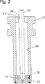
図2は燃料噴射弁の別の実施例を示しており、この場合、下流側の弁端部だけが図示してある。図1に示す実施例に対する相違点として、弁座支持体21の案内開口34の領域に互いに軸線平行に延びる複数の接続通路41が設けられている。弁座支持体21内への確実な流入を可能にするために、貫通開口24が大きな直径で形成されているのに対して、弁座支持体21の壁は薄く形成されている。
【0020】
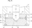
図3には、図2の燃料噴射弁の案内部分及び弁座部分が、本発明に基づき形成された該弁部分をさらに明瞭にするために、異なる尺度で示してある。弁座支持体21の噴射側の端部25で弁座支持体の貫通開口24内に設けられた案内部分及び弁座部分は、図3及び後に続く別のすべての図面に示す実施例では原理的に軸線方向に続くプレート状の、機能的に分離された3つの部材によって形成されており、該部材は互いに堅く結合されている。下流に向かって、案内部材35、著しく扁平な渦流部材47、次いで弁座部材26の順序で続いている。
【0021】
弁座部材26は部分的に、該弁座部材がゆるみなくわずかな遊びで弁座支持体21の貫通開口24の下側の区分49内へ貫通開口24内に設けられた段部51の下流側にはめ込まれ得るような外径を有している。案内部材35及び渦流部材47は実施例では弁座部材26よりもわずかに小さい外径を有している。
【0022】
案内部材35は内側に寸法の正確な案内開口55を有しており、該案内開口を介して弁ニードル20が軸線方向に運動する。さらに案内部材35は外周から、周囲にわたって分配された複数の切欠き56を有しており、これによって案内部材35の外周に沿って渦流部材47内へ、かつさらに弁座面27に向かう燃料流が保証されている。図10乃至図15を用いて、渦流部材47若しくは案内部材35の実施例を詳細に説明する。
【0023】
3つの部材35,47,26はそれぞれ端面で互いに直接に接触していて、かつ既に弁座支持体21内への組み込みの前に互いに堅く結合されて提供されている。プレート状の個別の部材35,47,26の堅い結合は、部材35,47,26の外周で材料接合的に行われ、この場合、溶接若しくはボンディングが有利な接合手段である。図3に示す実施例では、溶接点若しくは短い溶接継ぎ目60が所定の周区分に設けてあり、該周区分に案内部材35は切欠き56を有していない。3つの部材35,47,26の結合の後に、該部材を一回の緊締で案内開口55、弁座面27及び、案内部材35の上側の端面59が研削される。従って3つの面は極めてわずかな誤差しか有していない。
【0024】
複数のプレートから成る該弁部材全体が貫通開口24内へ、例えば案内部材35の上側の端面59を段部51に接触させるまで差し込まれる。弁部材の取り付け若しくは固定が例えば、弁座部材26と弁座支持体21との間で弁の下側の閉鎖部にレーザーを用いて形成可能な溶接継ぎ目61によって行われる。
【0025】
後に続く図面に示す別の実施例において、図2及び図3に示す実施例と変わらない若しくは同じく機能する部分には、同じ符号が付けてある。図4乃至図9並びに図16乃至図19に示す案内部分及び弁座部分はすべて3つのプレートの構造及び堅い結合部を有している。主として弁座部材26内の出口開口32の構造並びに弁座支持体21への弁座部材26の取り付けに差異がある。
【0026】
図4に示す実施例において、弁座部材26が環状のフランジ64を有しており、フランジが弁座支持体21の下流側の端部に係合している。環状のフランジ64の上面65が案内開口55及び弁座面27と一緒に研削される。3つのプレートの弁部材の差し込みは、フランジ64の上面65を弁座支持体21の端部25に当接させるまで行われる。該当接領域で両方の構成部分21,26は互いに溶接される。出口開口32は弁縦軸線8に対して斜めに傾斜されて形成され、下流側で凸面状に湾曲された噴射区分66内を延びている。
【0027】
図5に示す実施例は図4に示す実施例にほぼ相応するものであるが、相違点として、プレート状の付加的な第4の噴射部材67を噴射孔プレートの形で設けてあり、該噴射部材が出口開口32を有している。即ち、図4に比べて、弁座部材26が弁座面27の下流側で分割されている。噴射部材67と弁座部材26とは例えば、レーザー溶接によって得られる溶接継ぎ目68を介して互いに堅く結合されており、この場合、溶接は環状に巡る凹所69内に行われている。レーザー溶接の他に、ボンディング若しくは抵抗溶接も該結合のための特に適した接合手段である。噴射部材67の上面65′及び弁座支持体21の端面25の領域で両方の構成部分が互いに堅く結合される(溶接継ぎ目61)。
【0028】
弁座部材26は摩耗防止の理由から高い含有量の炭素を有していて、焼き入れされている。これによって溶接がしにくくなる。これに対して、噴射部材67は良好に溶接可能な材料から製造されている。溶接継ぎ目68はわずかにしか負荷されない。出口開口32は後で経済的に例えば穿孔によって形成されてよい。出口開口32の入口にシャープな孔縁部があり、これによって流れ内に乱れが生じて、その結果、噴霧が特に微細な液滴で行われる。
【0029】
図6の実施例は図3の実施例にほぼ類似している。この場合、弁座部材26が弁縦軸線8に対して傾斜して延びる出口開口32を有している。出口開口32は例えば、傾斜された円錐形の第1の区分71と下流側に続く傾斜された円筒形の第2の区分72に分けられており、この場合、弁縦軸線8に対する区分72の傾斜角度が弁縦軸線8に対する区分71の傾斜角度よりも大きくなっている。弁座部材26は凸面状に湾曲された中央の噴射区分66を有しており、該噴射区分内を出口開口32が延びている。出口開口32のこのような構造によって、燃料流が弁座部分から特に乱れないように出口開口32内へ転向される。これによって貫流拡散が最小にされる。変化例として、完全に円錐台形に延びる出口開口32が考えられる。
【0030】
図7に示す実施例においても、図5に示す実施例と類似してプレート状の付加的な第4の取り付け部材74が設けられている。弁座部材26が外周に段部75を有しており、段部が円形リング状の取り付け部材74によって取り囲まれている。良好に溶接可能な材料から成る取り付け部材74が溶接継ぎ目68を用いて弁座部材26に堅く結合されている。弁座部材26は例えば弁座面27と出口開口32との間に円筒形の区分76を有している。これによって出口開口32への移行部に内側の際だった噴射孔縁部(噴射孔エッジ)77が生じており、該噴射孔縁部で流れの鋭角な転向が行われる。これに起因する乱流が燃料の特に微細な噴霧に役立つ。
【0031】
図4の実施例に対してわずかに変更された実施例が図8に示してある。この場合には主な相違点が、弁座部材26の外周でフランジ64の上面65の上側に環状の溝78にある。フランジ64の上面65の研削に際して研削工具(図示せず)、例えば研削ディスク若しくは砥石車が有利には半径方向に深く弁座部材26内に押し込まれてよく、その結果、面積の大きな上面65が得られる。弁座支持体21の隣接の端部25の面取りが省略される。さらに、弁座部材26が溶接(溶接継ぎ目61)に際して弁座支持体21の縦軸線に関連して傾かないように良好に確保されている。
【0032】
図9は図7と比較可能な実施例を示しており、この場合、円形リング状の取り付け部材74の代わりにスリーブ状の取り付け部材74′を用いてあり、該取り付け部材が底部区分79で以て弁座部材26に堅く結合され、かつ周壁区分80で以て弁座支持体21に堅く結合されている。スリーブ状の取り付け部材74′は良好に溶接可能な部材から形成されている。従って、良好に溶接可能な2つの材料によって、高負荷可能な溶接継ぎ目61が得られる。これに対して、溶接継ぎ目68はわずかしか負荷されず、それというのは底部区分79が弁座部材26を部分的に取り囲んでいるからである。
【0033】
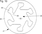
図10には、案内部材35と弁座部材26との間にはめ込み可能な渦流部材47が個別部材として平面を示してある。渦流部材47は経済的に例えば打ち抜き、ワイヤ放電加工、レーザー切断、エッチング、若しくは公知の別の手段で薄板から形成され、若しくは電気的なデポジットによって形成されてよい。渦流部材47内に内側の開口区分90を加工形成してあり、該開口区分は渦流部材47の軸線方向の厚さ全体にわたって延びている。開口区分90は、内側の1つの渦流室92(該渦流室を貫いて弁ニードル20の弁閉鎖区分28が延びている)と該渦流室92内へ開口する複数の渦流通路93によって形成されている。渦流通路93は接線方向で渦流室92内に開口していて、渦流室92と逆の側の端部95で以て渦流部材47の外周に接続されるものではない。むしろ、渦流通路93の入口ポケットとして形成された端部95と渦流部材47の外周との間に環状の縁部区分96が残されている。
【0034】
弁ニードル20を組み込んだ状態で、渦流室92が内側で弁ニードル20(弁閉鎖区分28)によってかつ、外側で渦流部材47の開口区分90の壁面によって制限されている。渦流室92内への渦流通路93の接線方向の開口に基づき、燃料が回転パルス(角運動)を強く受け、該回転パルスが引き続く流れ内で入口海溝32内まで維持される。このような遠心力に基づき燃料が中空円錐を成して噴射される。渦流通路93の端部95は大きな面積で捕集ポケットとして役立ち、燃料の乱れの少ない流入のためのリザーバーを成している。流れの転向によって燃料は低速でかつ乱れることなく本来の接線方向の渦流通路93内へ入り込み、ほぼ支障のない渦流が形成される。
【0035】
図11及び図12に案内部材35の2つの実施例を示してあり、しかしながら案内部材は別の多くの変化例でも実施可能である。案内部材35は外周にわたって交互に切欠き56及び歯状に突出する区分98を有している。歯状の区分98は鋭角に(図12)、若しくは丸味を付けて(図11)形成されていてよい。区分98及び切欠き56を対称的に形成してる場合には、案内部材35がひっくり返しても組み込まれ得る。案内部材35の製造は例えば打ち抜きによって行われる。図11の実施例では切欠き底部(切欠きの内側部分)99が傾斜して形成されており、これによって、切欠き底部99は有利な形式で、下側に位置する渦流部材47の渦流通路93の軸線に対して垂直に延びている。
【0036】
図13は図10の渦流部材47及び該渦流部材の上に配置される図12の案内部材35を組み立てた状態の平面図で示しており、明らかなように、渦流通路93の入口ポケットとしての端部95が区分98間の切欠き56の真下に配置されている。即ち、渦流部材47の渦流通路93の端部95と案内部材35の切欠き56とが回転位置(周方向)で互いに正確に整合されている。
【0037】
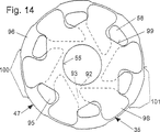
図14には、周囲にわたって分配された複数のセンタリング区分100を備えた渦流部材47及び、図11の案内部材35が上下に組み立てられた状態で示してある。渦流部材47は例えば、渦流通路93の数と同じ数で端部95の周方向領域にセンタリング区分100を有しており、該センタリング区分は渦流部材47の残り区分101よりもわずかに大きな外径を有している。周方向で見て、突出部を成すセンタリング区分100と引っ込められた残り区分101とが交互に位置している。溶接60が渦流部材47の引っ込められた残り区分101で行われる。センタリング区分100が弁座支持体21の貫通開口24の下側の区分49内での弁部材全体のセンタリングを行う。
【0038】
渦流部材47のセンタリング区分100に類似して、案内部材35の区分98も半径方向にわずかに突出したセンタリング区分100′として形成されていてよい。図15には、図10の渦流部材47及び図11のものに類似する案内部材35が上下に組み立てられた状態で示してあり、この場合、案内部材35が周囲にわたって分配された複数のセンタリング区分100′を備えている。案内部材35の、例えば1つおきの区分98が該区分間に位置する区分98よりも半径方向にわずかに長く延びており、この場合、センタリング区分100′が渦流部材47の外径をわずかに越えて突出しており、その結果、弁座支持体21内でのセンタリングが可能である。
【0039】
図16、図17、図18及び図19に別の3つの実施例を示してあり、該実施例は図1乃至図15に示す実施例に対して、案内部材35が下流側に隣接する渦流部材47よりも小さな外径で形成されていることによって異なっており、これによって、案内部材35と、渦流部材47と、弁座部材26との材料接合的な結合のための別の可能性が得られる。図16の案内部分及び弁座部分の平面図から明らかなように、案内部材35が、渦流通路93の入口ポケットとして形成された端部を少なくとも部分的に露出させるような外径で形成されている。これによって、案内部材35の、切欠き56を備えた歯車状の構造(図11及び図12、参照)が使用されなくてよく、それというのは燃料が外周から直接に渦流通路93の端部95内に流入できるからである。案内部材35が該案内部材自体の簡単な幾何学構造に基づき極めて経済的に、例えば打ち抜きによって形成可能である。案内部材35と渦流部材47との間の、前に述べた実施例では必要であった回転位置の正確な整合も不要である。案内部材35は渦流部材47に対してカバーを成すにすぎず、渦流部材が渦流通路93の位置に左右されずに取り付けられ得る。
【0040】
理想的な形式では、渦流通路93の端部95が周方向に延びる延長部103によって次のように大きく形成されており、即ち、各端部95の領域に溶接点若しくは短い溶接継ぎ目60が設けられる。この場合、溶接点若しくは短い溶接継ぎ目60は、案内部材35の外縁部が渦流通路93の端部95の延長部103の制限壁とちょうど合致する箇所に設けられており、これによって案内部材35と、渦流部材47と、弁座部材26との材料接合的な堅い結合が特に簡単かつ経済的に達成される。渦流通路93の数に対応して、同じ数の溶接点60が設けられている。図17から明らかなように、溶接点若しくは短い溶接継ぎ目60は貫通溶接部(通し溶接部)として3つのすべての部材35,47,26に係合しており、これによって極めて確実な結合が得られる。
【0041】
図18及び図19に示す実施例では、渦流通路93の端部95に左右されることのない貫通溶接部が設けられている。溶接点若しくは短い溶接継ぎ目60は端部95間の周方向区分で材料を貫通しており、このために高い溶接エネルギーが必要である。溶接点若しくは短い溶接継ぎ目60は、ちょうど案内部材35の外縁部に配置されている。図18及び図19から明らかなように、溶接継ぎ目60はすみ肉溶接の形で貫通溶接部(Durchschweissung)として3つの部材35,47,26を互いに堅く結合している。溶接継ぎ目60の数は、例えば渦流通路93の数と同じである。図19は極めて簡単な実施例の弁座部材26を示しており、該弁座部材は外側輪郭に段部のない柱体片状の構成部分として形成されていて、従ってたわみに対して極めて剛性的である。弁座部材26は段部なしに形成された上面65の半径方向外側の区分で弁座支持体21に接触しており、従って、両方の構成部分を堅く結合するために溶接継ぎ目61が極めて簡単に設けられ得る。
【図面の簡単な説明】
【図1】 燃料噴射弁の第1実施例を示す図。
【図2】 燃料噴射弁の第2実施例を示す図。
【図3】 図2の案内部分及び弁座部分の第1実施例の拡大図。
【図4】 案内部分及び弁座部分の第2実施例を示す図。
【図5】 案内部分及び弁座部分の第3実施例を示す図。
【図6】 案内部分及び弁座部分の第4実施例を示す図。
【図7】 案内部分及び弁座部分の第5実施例を示す図。
【図8】 案内部分及び弁座部分の第6実施例を示す図。
【図9】 案内部分及び弁座部分の第7実施例を示す図。
【図10】 渦流部材を示す図。
【図11】 案内部材の第1実施例を示す図。
【図12】 案内部材の第2実施例を示す図。
【図13】 図10の渦流部材及び、図12の案内部材を上下に組み立てた状態で示す図。
【図14】 センタリング区分の備えられた渦流部材及び、図11の案内部材を上下に組み立てた状態で示す図。
【図15】 図10の渦流部材及び、センタリング区分の備えられた案内部材を上下に組み立てた状態で示す図。
【図16】 案内部分及び弁座部分の第8実施例の平面図。
【図17】 図16のXVII−XVII線に沿った断面図。
【図18】 案内部分及び弁座部分の第9実施例を示す図。
【図19】 案内部分及び弁座部分の第10実施例を示す図。
【符号の説明】
1 磁気コイル、2 コア、3 コイル本体、4 中間部分、7 縦開口、8 弁縦軸線、14 ケーシング部分、15 燃料フィルタ、18 ケーシング部分、19 可動子、20 弁ニードル、21 弁座支持体、22 シールリング、24 貫通開口、25 端部、26 弁座部材、27 弁座面、28 弁閉鎖区分、32 出口開口、33 戻しばね、34 案内開口、35 案内部材、38 調節スリーブ、39 センタリング片、40 孔状の流過通路、41 接続通路、43 接点部材、44 プラスチック射出成形部分、45 接続ケーブル、47 渦流部材、49 区分、55 案内開口、56 切欠き、59 端面、60,61 溶接継ぎ目、64 フランジ、65 上面、66 噴射区分、67 噴射部材、68 溶接継ぎ目、74 取り付け部材、75 段部、76 区分、77 噴射孔縁部、78 溝、79 底部区分、80 周壁区分、90 開口区分、92 渦流室、93 渦流通路、95 端部、96 縁部区分、98 区分、100 センタリング区分[0001]
Background art
The invention relates to a fuel injection valve of the type described in the superordinate concept of the independent claims.
[0002]
German Patent No. 3,943,005 discloses an electromagnetically actuable fuel injection valve, in which a plurality of plate-like members are arranged in the valve seat part. When exciting the magnetic circuit, a flat valve plate that functions as a flat mover is lifted from a valve seat plate that cooperates with the valve plate, and these plates together form a plate valve portion. Yes. A vortex member is disposed upstream of the valve seat plate, and the vortex member causes a rotational motion in the fuel flowing toward the valve seat. The stopper plate limits the stroke of the valve plate in the axial direction on the side facing the valve seat plate. The valve plate is surrounded by a swirl member with great play, so that some guidance of the valve plate is provided by the swirl member. A plurality of grooves extending in the tangential direction are provided on the lower end face of the vortex member, and the grooves start from the outer periphery and reach the central vortex chamber. The groove is formed as a vortex passage by mounting the vortex member on the valve seat plate with the lower end face.
[0003]
Furthermore, in the fuel injection valve known from European Patent Application No. 0350885, a valve seat member is provided, and a valve closing member arranged on a valve needle capable of axial movement is connected to the valve seat surface of the valve seat member. It comes to cooperate. A vortex member is disposed in the notch of the valve seat member on the upstream side of the valve seat surface, and the valve seat member causes rotational movement in the fuel flowing toward the valve seat. The stopper plate restricts the stroke of the valve needle in the axial direction and has an opening in the center, which serves to provide some guidance of the valve needle. The valve needle is surrounded by an opening in the stopper plate with great play, since the fuel to be supplied towards the valve seat must also pass through the opening. A plurality of grooves extending in the tangential direction are provided on the lower end face of the vortex member, and the grooves start from the outer periphery and reach the central vortex chamber. A groove is formed as a vortex passage by mounting the vortex member on the valve seat member with the lower end face.
[0004]
Advantages of the invention
In the fuel injector according to the invention having the structure described in the characterizing part of the independent claim, the fuel injector can be produced economically with a particularly simple structure. In this case, the end of the injection valve, in particular the downstream side, can be simply and nevertheless very accurately assembled. A further advantage resides in precision machining of the guide member and valve seat member surfaces. The guide opening in the guide member, the valve seat surface of the valve seat member, the guide member or the valve seat is based on the rigid coupling of the guide member, the vortex member and the valve seat member which has already taken place before assembly into the injection valve. The contact surface of the member that will eventually come into contact with the valve casing or the valve seat support can be precision machined, for example ground (polished), with a single clamping.
[0005]
Furthermore, the plate-like swirl member is very simply structured and can therefore be formed easily. The vortex member has a role of causing a vortex motion or a rotational motion in the fuel and preventing an undesirable turbulent flow from being generated in the fluid as much as possible. All other valve functions are undertaken by other components of the valve. Therefore, the vortex member can be processed optimally. Since the vortex member is a separate component, it is not subject to limitations (constraints) during the manufacturing process. Compared with a vortex member having a groove or a similar recess for forming a vortex on the end face, the vortex member according to the invention can form an inner opening section with very simple means, the opening section being a vortex It extends over the entire axial thickness of the member and is surrounded by an outer annular edge section.
[0006]
By means of the dependent claims, advantageous configurations and improvements of the fuel injection valve according to the independent claims are possible.
[0007]
Similar to the swirl member and the valve seat member, the guide member can be easily manufactured. In a particularly advantageous manner, the guide member is an inner guide opening and serves to guide the valve needle through the guide opening. Based on the structure with alternately protruding teeth on the outer periphery of the guide member and recesses located between the sections, it is easy to guarantee the optimal inflow of the lower vortex member into the vortex passage. can do.
[0008]
The advantage gained by the modular construction of the components and the functional separation associated therewith is that the individual components can be configured very flexibly, so that different sprays (sprays) to be sprayed with a simple variation of one component. Angle, injection amount). Furthermore, additional injection members or attachment members can be provided in a simple manner. Despite the fragile structure of the individual members, such a valve member can be handled (handled) very easily on the basis that all the members are firmly connected to one another.
[0009]
Description of Examples
An electromagnetically operable valve in the form of an injection valve for a fuel injection device of an externally ignited internal combustion engine, shown as an example in FIG. 1, comprises a
[0010]
A
[0011]
The
[0012]
In the embodiment shown in FIG. 1, the
[0013]
The
[0014]
The operation of the injection valve is performed electromagnetically in a known manner. A piezoelectric actuator as an actuatable actuating member is also conceivable. It is also conceivable to operate via a piston which can be controlled and pressure loaded. Due to the axial movement of the
[0015]
Another plate-like member, also a
[0016]
A spring preload (spring load or initial tightening) of the return spring 33 in which the adjusting
[0017]
The stroke of the
[0018]
Electrical contact of the
[0019]
FIG. 2 shows another embodiment of the fuel injection valve, in which only the downstream valve end is shown. As a difference from the embodiment shown in FIG. 1, a plurality of
[0020]
In FIG. 3, the guide portion and the valve seat portion of the fuel injection valve of FIG. 2 are shown on different scales to further clarify the valve portion formed in accordance with the present invention. The guide portion and the valve seat portion provided in the through opening 24 of the valve seat support at the injection side end 25 of the
[0021]
The
[0022]
The
[0023]
The three
[0024]
The entire valve member composed of a plurality of plates is inserted into the through
[0025]
In another embodiment shown in the subsequent drawings, parts that are the same as or function the same as those in the embodiment shown in FIGS. 2 and 3 are given the same reference numerals. The guide portion and valve seat portion shown in FIGS. 4 to 9 and FIGS. 16 to 19 all have a three-plate structure and a rigid joint. There are mainly differences in the structure of the outlet opening 32 in the
[0026]
In the embodiment shown in FIG. 4, the
[0027]
The embodiment shown in FIG. 5 substantially corresponds to the embodiment shown in FIG. 4, except that an additional plate-like
[0028]
The
[0029]
The embodiment of FIG. 6 is substantially similar to the embodiment of FIG. In this case, the
[0030]
In the embodiment shown in FIG. 7 as well, an additional plate-like fourth mounting
[0031]
A slight modification to the embodiment of FIG. 4 is shown in FIG. In this case, the main difference is in the
[0032]
FIG. 9 shows an embodiment comparable to FIG. 7, in which a sleeve-like mounting
[0033]
In FIG. 10, a
[0034]
With the
[0035]
11 and 12 show two embodiments of the
[0036]
FIG. 13 is a plan view showing the assembled state of the
[0037]
FIG. 14 shows the
[0038]
Similar to the centering
[0039]
16, 17, 18, and 19 show three other embodiments, which are different from the embodiments shown in FIGS. 1 to 15 in that the
[0040]
In an ideal form, the
[0041]
In the embodiment shown in FIGS. 18 and 19, a through-weld portion that does not depend on the
[Brief description of the drawings]
FIG. 1 is a view showing a first embodiment of a fuel injection valve.
FIG. 2 is a view showing a second embodiment of the fuel injection valve.
FIG. 3 is an enlarged view of the first embodiment of the guide portion and the valve seat portion of FIG. 2;
FIG. 4 is a view showing a second embodiment of the guide portion and the valve seat portion.
FIG. 5 is a view showing a third embodiment of the guide portion and the valve seat portion.
FIG. 6 is a view showing a fourth embodiment of the guide portion and the valve seat portion.
FIG. 7 is a view showing a fifth embodiment of the guide portion and the valve seat portion.
FIG. 8 is a view showing a sixth embodiment of the guide portion and the valve seat portion.
FIG. 9 is a view showing a seventh embodiment of the guide portion and the valve seat portion.
FIG. 10 is a view showing a vortex member.
FIG. 11 is a view showing a first embodiment of the guide member.
FIG. 12 is a view showing a second embodiment of the guide member.
13 is a view showing the vortex member shown in FIG. 10 and the guide member shown in FIG. 12 in an assembled state.
FIG. 14 is a view showing the vortex member provided with the centering section and the guide member of FIG. 11 in an assembled state up and down.
15 is a view showing the vortex member of FIG. 10 and a guide member provided with a centering section in an assembled state up and down. FIG.
FIG. 16 is a plan view of an eighth embodiment of a guide portion and a valve seat portion.
17 is a cross-sectional view taken along line XVII-XVII in FIG.
FIG. 18 is a view showing a ninth embodiment of the guide portion and the valve seat portion.
FIG. 19 is a view showing a tenth embodiment of the guide portion and the valve seat portion.
[Explanation of symbols]
DESCRIPTION OF
Claims (7)
Applications Claiming Priority (5)
| Application Number | Priority Date | Filing Date | Title |
|---|---|---|---|
| DE19838949 | 1998-08-27 | ||
| DE19838949.3 | 1998-08-27 | ||
| DE19927196A DE19927196A1 (en) | 1998-08-27 | 1999-06-15 | Fuel injector |
| DE19927196.8 | 1999-06-15 | ||
| PCT/DE1999/002657 WO2000012891A1 (en) | 1998-08-27 | 1999-08-25 | Fuel injection valve |
Related Child Applications (1)
| Application Number | Title | Priority Date | Filing Date |
|---|---|---|---|
| JP2010170014A Division JP5114537B2 (en) | 1998-08-27 | 2010-07-29 | Fuel injection valve |
Publications (2)
| Publication Number | Publication Date |
|---|---|
| JP2002523682A JP2002523682A (en) | 2002-07-30 |
| JP4593784B2 true JP4593784B2 (en) | 2010-12-08 |
Family
ID=26048420
Family Applications (1)
| Application Number | Title | Priority Date | Filing Date |
|---|---|---|---|
| JP2000567844A Expired - Fee Related JP4593784B2 (en) | 1998-08-27 | 1999-08-25 | Fuel injection valve |
Country Status (9)
| Country | Link |
|---|---|
| US (1) | US6296199B1 (en) |
| EP (1) | EP1049871B1 (en) |
| JP (1) | JP4593784B2 (en) |
| CN (1) | CN1104555C (en) |
| AU (1) | AU741787B2 (en) |
| BR (1) | BR9906683A (en) |
| ES (1) | ES2205895T3 (en) |
| RU (1) | RU2227226C2 (en) |
| WO (1) | WO2000012891A1 (en) |
Families Citing this family (31)
| Publication number | Priority date | Publication date | Assignee | Title |
|---|---|---|---|---|
| DE10046305A1 (en) * | 2000-09-19 | 2002-04-04 | Bosch Gmbh Robert | Fuel injector |
| DE10049034B4 (en) * | 2000-10-04 | 2005-08-04 | Robert Bosch Gmbh | Fuel injector |
| DE10055513B4 (en) | 2000-11-09 | 2006-03-09 | Robert Bosch Gmbh | Fuel injector |
| DE10063259A1 (en) * | 2000-12-19 | 2002-07-11 | Bosch Gmbh Robert | Fuel injector |
| DE10103051B4 (en) * | 2001-01-24 | 2006-07-27 | Robert Bosch Gmbh | Fuel injector |
| ITBO20010279A1 (en) * | 2001-05-08 | 2002-11-08 | Magneti Marelli Spa | FUEL INJECTOR WITH PIEZOELECTRIC ACTUATOR HOUSED IN AN INSULATED CHAMBER |
| ITBO20010482A1 (en) * | 2001-07-27 | 2003-01-27 | Magneti Marelli Powertrain Spa | VALVE BODY FOR A FUEL INJECTOR |
| US6899290B2 (en) * | 2002-06-24 | 2005-05-31 | Delphi Technologies, Inc. | Fuel swirler plate for a fuel injector |
| US7021570B2 (en) * | 2002-07-29 | 2006-04-04 | Denso Corporation | Fuel injection device having injection hole plate |
| EP1482170B1 (en) * | 2003-05-26 | 2008-04-09 | VDO Automotive AG | Injection nozzle with an improved injection function and method for producing an injection nozzle |
| DE602004005152T2 (en) * | 2004-01-28 | 2007-07-12 | Siemens Vdo Automotive S.P.A., Fauglia | Valve body, fluid injector and method of manufacturing a valve body |
| US7137577B2 (en) * | 2004-11-05 | 2006-11-21 | Visteon Global Technologies, Inc. | Low pressure fuel injector nozzle |
| US7168637B2 (en) * | 2004-11-05 | 2007-01-30 | Visteon Global Technologies, Inc. | Low pressure fuel injector nozzle |
| US7438241B2 (en) * | 2004-11-05 | 2008-10-21 | Visteon Global Technologies, Inc. | Low pressure fuel injector nozzle |
| US7185831B2 (en) * | 2004-11-05 | 2007-03-06 | Ford Motor Company | Low pressure fuel injector nozzle |
| US7051957B1 (en) * | 2004-11-05 | 2006-05-30 | Visteon Global Technologies, Inc. | Low pressure fuel injector nozzle |
| US7104475B2 (en) * | 2004-11-05 | 2006-09-12 | Visteon Global Technologies, Inc. | Low pressure fuel injector nozzle |
| US7198207B2 (en) * | 2004-11-05 | 2007-04-03 | Visteon Global Technologies, Inc. | Low pressure fuel injector nozzle |
| US7124963B2 (en) * | 2004-11-05 | 2006-10-24 | Visteon Global Technologies, Inc. | Low pressure fuel injector nozzle |
| US8517284B2 (en) | 2009-05-13 | 2013-08-27 | Caterpillar Inc. | System and method for internal cooling of a fuel injector |
| JP2011069264A (en) * | 2009-09-25 | 2011-04-07 | Hitachi Automotive Systems Ltd | Fuel injection valve |
| JP2012026466A (en) * | 2010-07-20 | 2012-02-09 | Advics Co Ltd | Electromagnetic valve |
| KR101154579B1 (en) * | 2010-11-23 | 2012-06-08 | 현대자동차주식회사 | Injector Hole Structure for Engine |
| CN103256106B (en) * | 2012-12-28 | 2015-12-23 | 湖南吉利汽车部件有限公司 | Without Aeroassisted SCR ejecting system |
| JP6080087B2 (en) * | 2014-02-28 | 2017-02-15 | 株式会社デンソー | Fuel injection valve |
| JP6354651B2 (en) * | 2015-04-24 | 2018-07-11 | 株式会社デンソー | Valve device and device for manufacturing valve device |
| US10927739B2 (en) * | 2016-12-23 | 2021-02-23 | Cummins Emission Solutions Inc. | Injector including swirl device |
| CN107956619B (en) * | 2017-11-24 | 2020-07-07 | 广西卡迪亚科技有限公司 | Single-hole atomizing oil sprayer and rotational flow atomizing structure thereof |
| CN107725243A (en) * | 2017-11-24 | 2018-02-23 | 广西卡迪亚科技有限公司 | A kind of single-hole atomization fuel injector and its rearmounted atomization structure |
| DE102019104294A1 (en) * | 2018-03-15 | 2019-09-19 | Denso Corporation | Corrosion resistant device |
| JP7445602B2 (en) * | 2018-04-25 | 2024-03-07 | ロベルト・ボッシュ・ゲゼルシャフト・ミト・ベシュレンクテル・ハフツング | Fuel injector valve seat assembly including insert seal features |
Family Cites Families (12)
| Publication number | Priority date | Publication date | Assignee | Title |
|---|---|---|---|---|
| JPH0816471B2 (en) * | 1987-07-31 | 1996-02-21 | 株式会社日立製作所 | Electromagnetic fuel injection valve |
| KR930004967B1 (en) | 1988-07-13 | 1993-06-11 | 가부시기가이샤 히다찌세이사꾸쇼 | Electronic fuel injector |
| DE3943005A1 (en) * | 1988-12-28 | 1990-07-05 | Hitachi Ltd | ELECTROMAGNETIC INJECTOR DEVICE |
| US5086979A (en) * | 1989-07-07 | 1992-02-11 | Fuel Systems Textron Inc. | Small airblast fuel nozzle with high efficiency inner air swirler |
| US5437413A (en) * | 1994-03-24 | 1995-08-01 | Siemens Automotive L.P. | Multiple disk air assist atomizer for fuel injection |
| US5570841A (en) * | 1994-10-07 | 1996-11-05 | Siemens Automotive Corporation | Multiple disk swirl atomizer for fuel injector |
| DE19638201B4 (en) * | 1996-09-19 | 2005-05-04 | Robert Bosch Gmbh | Fuel injector |
| JP3933739B2 (en) * | 1997-01-30 | 2007-06-20 | 三菱電機株式会社 | Fuel injection valve |
| US5875972A (en) * | 1997-02-06 | 1999-03-02 | Siemens Automotive Corporation | Swirl generator in a fuel injector |
| DE19736682A1 (en) | 1997-08-22 | 1999-02-25 | Bosch Gmbh Robert | Fuel injector for internal combustion engine |
| US5996912A (en) * | 1997-12-23 | 1999-12-07 | Siemens Automotive Corporation | Flat needle for pressurized swirl fuel injector |
| US6065692A (en) * | 1999-06-09 | 2000-05-23 | Siemens Automotive Corporation | Valve seat subassembly for fuel injector |
-
1999
- 1999-08-25 RU RU2000112646/06A patent/RU2227226C2/en not_active IP Right Cessation
- 1999-08-25 EP EP99953590A patent/EP1049871B1/en not_active Expired - Lifetime
- 1999-08-25 US US09/530,329 patent/US6296199B1/en not_active Expired - Lifetime
- 1999-08-25 BR BR9906683-1A patent/BR9906683A/en active Search and Examination
- 1999-08-25 CN CN99801475A patent/CN1104555C/en not_active Expired - Fee Related
- 1999-08-25 ES ES99953590T patent/ES2205895T3/en not_active Expired - Lifetime
- 1999-08-25 AU AU10287/00A patent/AU741787B2/en not_active Ceased
- 1999-08-25 WO PCT/DE1999/002657 patent/WO2000012891A1/en not_active Application Discontinuation
- 1999-08-25 JP JP2000567844A patent/JP4593784B2/en not_active Expired - Fee Related
Also Published As
| Publication number | Publication date |
|---|---|
| CN1275185A (en) | 2000-11-29 |
| EP1049871A1 (en) | 2000-11-08 |
| CN1104555C (en) | 2003-04-02 |
| BR9906683A (en) | 2000-10-17 |
| EP1049871B1 (en) | 2003-07-30 |
| WO2000012891A1 (en) | 2000-03-09 |
| US6296199B1 (en) | 2001-10-02 |
| JP2002523682A (en) | 2002-07-30 |
| ES2205895T3 (en) | 2004-05-01 |
| AU1028700A (en) | 2000-03-21 |
| RU2227226C2 (en) | 2004-04-20 |
| AU741787B2 (en) | 2001-12-06 |
Similar Documents
| Publication | Publication Date | Title |
|---|---|---|
| JP4593784B2 (en) | Fuel injection valve | |
| JP5114537B2 (en) | Fuel injection valve | |
| JP4097713B2 (en) | Fuel injection valve | |
| KR100744439B1 (en) | Fuel injection valve | |
| US6382533B1 (en) | Fuel injection valve | |
| JPH07301357A (en) | Valve needle of solenoid valve | |
| JP2001504913A (en) | Fuel injection valve | |
| JP5517942B2 (en) | Electromagnetically operated fuel injection valve | |
| JP4469502B2 (en) | Fuel injection valve | |
| JP2004518910A (en) | Fuel injection valve | |
| US20030192965A1 (en) | Fuel injection valve | |
| KR20010052202A (en) | Method for mounting a valve module of a fuel injector | |
| KR100630606B1 (en) | Fuel Injection Valve | |
| JPH11200998A (en) | Fluid injection nozzle | |
| JP2002115625A (en) | Fuel injection valve | |
| JP2001505277A (en) | Solenoid operated valve | |
| US6317978B2 (en) | Electromagnetically actuated valve | |
| JP2004509284A (en) | Fuel injection valve | |
| EP1811166B1 (en) | Valve assembly for an injection valve and injection valve | |
| JP2004509286A (en) | Fuel injection valve | |
| US7080796B2 (en) | Fuel injection valve | |
| JP4096008B2 (en) | Method for manufacturing a fuel injection valve and fuel injection valve | |
| JP2004517267A (en) | Fuel injection valve | |
| JP2002507695A (en) | Fuel injection valve | |
| JP2004511720A (en) | Fuel injection valve |
Legal Events
| Date | Code | Title | Description |
|---|---|---|---|
| A621 | Written request for application examination |
Free format text: JAPANESE INTERMEDIATE CODE: A621 Effective date: 20060824 |
|
| A131 | Notification of reasons for refusal |
Free format text: JAPANESE INTERMEDIATE CODE: A131 Effective date: 20090423 |
|
| A601 | Written request for extension of time |
Free format text: JAPANESE INTERMEDIATE CODE: A601 Effective date: 20090723 |
|
| A602 | Written permission of extension of time |
Free format text: JAPANESE INTERMEDIATE CODE: A602 Effective date: 20090730 |
|
| A601 | Written request for extension of time |
Free format text: JAPANESE INTERMEDIATE CODE: A601 Effective date: 20090824 |
|
| A602 | Written permission of extension of time |
Free format text: JAPANESE INTERMEDIATE CODE: A602 Effective date: 20090831 |
|
| A601 | Written request for extension of time |
Free format text: JAPANESE INTERMEDIATE CODE: A601 Effective date: 20090918 |
|
| A602 | Written permission of extension of time |
Free format text: JAPANESE INTERMEDIATE CODE: A602 Effective date: 20090930 |
|
| A521 | Written amendment |
Free format text: JAPANESE INTERMEDIATE CODE: A523 Effective date: 20091022 |
|
| A131 | Notification of reasons for refusal |
Free format text: JAPANESE INTERMEDIATE CODE: A131 Effective date: 20100129 |
|
| A601 | Written request for extension of time |
Free format text: JAPANESE INTERMEDIATE CODE: A601 Effective date: 20100430 |
|
| A602 | Written permission of extension of time |
Free format text: JAPANESE INTERMEDIATE CODE: A602 Effective date: 20100512 |
|
| A601 | Written request for extension of time |
Free format text: JAPANESE INTERMEDIATE CODE: A601 Effective date: 20100531 |
|
| A602 | Written permission of extension of time |
Free format text: JAPANESE INTERMEDIATE CODE: A602 Effective date: 20100607 |
|
| A601 | Written request for extension of time |
Free format text: JAPANESE INTERMEDIATE CODE: A601 Effective date: 20100629 |
|
| A602 | Written permission of extension of time |
Free format text: JAPANESE INTERMEDIATE CODE: A602 Effective date: 20100706 |
|
| A521 | Written amendment |
Free format text: JAPANESE INTERMEDIATE CODE: A523 Effective date: 20100729 |
|
| TRDD | Decision of grant or rejection written | ||
| A01 | Written decision to grant a patent or to grant a registration (utility model) |
Free format text: JAPANESE INTERMEDIATE CODE: A01 Effective date: 20100818 |
|
| A01 | Written decision to grant a patent or to grant a registration (utility model) |
Free format text: JAPANESE INTERMEDIATE CODE: A01 |
|
| A61 | First payment of annual fees (during grant procedure) |
Free format text: JAPANESE INTERMEDIATE CODE: A61 Effective date: 20100916 |
|
| FPAY | Renewal fee payment (event date is renewal date of database) |
Free format text: PAYMENT UNTIL: 20130924 Year of fee payment: 3 |
|
| R150 | Certificate of patent or registration of utility model |
Free format text: JAPANESE INTERMEDIATE CODE: R150 |
|
| R250 | Receipt of annual fees |
Free format text: JAPANESE INTERMEDIATE CODE: R250 |
|
| R250 | Receipt of annual fees |
Free format text: JAPANESE INTERMEDIATE CODE: R250 |
|
| R250 | Receipt of annual fees |
Free format text: JAPANESE INTERMEDIATE CODE: R250 |
|
| LAPS | Cancellation because of no payment of annual fees |