EP1340943A2 - Ofen für Festbrennstoffe - Google Patents
Ofen für Festbrennstoffe Download PDFInfo
- Publication number
- EP1340943A2 EP1340943A2 EP03002816A EP03002816A EP1340943A2 EP 1340943 A2 EP1340943 A2 EP 1340943A2 EP 03002816 A EP03002816 A EP 03002816A EP 03002816 A EP03002816 A EP 03002816A EP 1340943 A2 EP1340943 A2 EP 1340943A2
- Authority
- EP
- European Patent Office
- Prior art keywords
- furnace
- air
- openings
- oven
- chamber
- Prior art date
- Legal status (The legal status is an assumption and is not a legal conclusion. Google has not performed a legal analysis and makes no representation as to the accuracy of the status listed.)
- Granted
Links
- 239000004449 solid propellant Substances 0.000 title claims abstract description 5
- 239000000446 fuel Substances 0.000 claims abstract description 6
- 238000002485 combustion reaction Methods 0.000 claims description 35
- 239000007789 gas Substances 0.000 claims description 15
- 239000003546 flue gas Substances 0.000 claims description 14
- 238000010304 firing Methods 0.000 claims description 12
- UGFAIRIUMAVXCW-UHFFFAOYSA-N Carbon monoxide Chemical compound [O+]#[C-] UGFAIRIUMAVXCW-UHFFFAOYSA-N 0.000 claims description 10
- 239000002023 wood Substances 0.000 claims description 4
- 238000003860 storage Methods 0.000 claims description 3
- 239000011449 brick Substances 0.000 abstract 1
- 238000010438 heat treatment Methods 0.000 description 6
- 230000002349 favourable effect Effects 0.000 description 4
- 230000008901 benefit Effects 0.000 description 3
- 238000011049 filling Methods 0.000 description 3
- 238000004519 manufacturing process Methods 0.000 description 3
- 239000000203 mixture Substances 0.000 description 3
- 238000000197 pyrolysis Methods 0.000 description 3
- XLYOFNOQVPJJNP-UHFFFAOYSA-N water Substances O XLYOFNOQVPJJNP-UHFFFAOYSA-N 0.000 description 3
- QVGXLLKOCUKJST-UHFFFAOYSA-N atomic oxygen Chemical compound [O] QVGXLLKOCUKJST-UHFFFAOYSA-N 0.000 description 2
- 239000002737 fuel gas Substances 0.000 description 2
- 206010022000 influenza Diseases 0.000 description 2
- 238000009434 installation Methods 0.000 description 2
- JEIPFZHSYJVQDO-UHFFFAOYSA-N iron(III) oxide Inorganic materials O=[Fe]O[Fe]=O JEIPFZHSYJVQDO-UHFFFAOYSA-N 0.000 description 2
- 239000000463 material Substances 0.000 description 2
- 230000003647 oxidation Effects 0.000 description 2
- 238000007254 oxidation reaction Methods 0.000 description 2
- 239000001301 oxygen Substances 0.000 description 2
- 229910052760 oxygen Inorganic materials 0.000 description 2
- 238000003763 carbonization Methods 0.000 description 1
- 239000003610 charcoal Substances 0.000 description 1
- 238000007872 degassing Methods 0.000 description 1
- 238000009826 distribution Methods 0.000 description 1
- 230000000694 effects Effects 0.000 description 1
- 238000005516 engineering process Methods 0.000 description 1
- 238000000605 extraction Methods 0.000 description 1
- 238000011010 flushing procedure Methods 0.000 description 1
- 238000007210 heterogeneous catalysis Methods 0.000 description 1
- 238000009413 insulation Methods 0.000 description 1
- 230000003993 interaction Effects 0.000 description 1
- 238000011068 loading method Methods 0.000 description 1
- 239000002184 metal Substances 0.000 description 1
- 238000002156 mixing Methods 0.000 description 1
- 238000005457 optimization Methods 0.000 description 1
- 230000002441 reversible effect Effects 0.000 description 1
- 239000000523 sample Substances 0.000 description 1
- 238000007789 sealing Methods 0.000 description 1
- 238000000926 separation method Methods 0.000 description 1
- 239000000779 smoke Substances 0.000 description 1
- 239000007787 solid Substances 0.000 description 1
- 238000005979 thermal decomposition reaction Methods 0.000 description 1
- 238000009423 ventilation Methods 0.000 description 1
- 230000000007 visual effect Effects 0.000 description 1
Images




Classifications
-
- F—MECHANICAL ENGINEERING; LIGHTING; HEATING; WEAPONS; BLASTING
- F24—HEATING; RANGES; VENTILATING
- F24B—DOMESTIC STOVES OR RANGES FOR SOLID FUELS; IMPLEMENTS FOR USE IN CONNECTION WITH STOVES OR RANGES
- F24B5/00—Combustion-air or flue-gas circulation in or around stoves or ranges
- F24B5/02—Combustion-air or flue-gas circulation in or around stoves or ranges in or around stoves
- F24B5/04—Combustion-air or flue-gas circulation in or around stoves or ranges in or around stoves the air or gas passing downwards through the bottom of the stove of fire grate
-
- F—MECHANICAL ENGINEERING; LIGHTING; HEATING; WEAPONS; BLASTING
- F24—HEATING; RANGES; VENTILATING
- F24B—DOMESTIC STOVES OR RANGES FOR SOLID FUELS; IMPLEMENTS FOR USE IN CONNECTION WITH STOVES OR RANGES
- F24B1/00—Stoves or ranges
- F24B1/02—Closed stoves
- F24B1/026—Closed stoves with several combustion zones
-
- F—MECHANICAL ENGINEERING; LIGHTING; HEATING; WEAPONS; BLASTING
- F24—HEATING; RANGES; VENTILATING
- F24B—DOMESTIC STOVES OR RANGES FOR SOLID FUELS; IMPLEMENTS FOR USE IN CONNECTION WITH STOVES OR RANGES
- F24B5/00—Combustion-air or flue-gas circulation in or around stoves or ranges
- F24B5/02—Combustion-air or flue-gas circulation in or around stoves or ranges in or around stoves
- F24B5/021—Combustion-air or flue-gas circulation in or around stoves or ranges in or around stoves combustion-air circulation
- F24B5/026—Supply of primary and secondary air for combustion
Definitions
- the invention relates to a furnace for solid fuels, especially wood, according to the Preamble of claim 1.
- FR 2 558 241 A1 describes an oven for solids with a generally box-shaped structure described.
- a rectangular combustion chamber is located between two floor panels a funnel-shaped prechamber with a grate on top. It becomes primary air preheated, on the one hand, with secondary air coming from the front of the furnace flows down through an annular gap past the antechamber. on the other hand the supply air passes through openings in the upper base plate and above it Short pipes protruding upwards through the antechamber into the combustion chamber.
- the structure includes a kettle with a lower inlet for cold water and an upper outlet for hot water.
- a shaft on the back of the boiler is used for Extraction of the flue gas by a fan and as a heat exchanger.
- both primary and secondary air are passed through adjacent ones Inlets fed into the furnace combustion chamber, each through a series of openings above the firing support, with a conical ring channel for the secondary air supply is provided.
- a conical ring channel for the secondary air supply is provided.
- a furnace of a similar type is described in DE 39 35 846 C2. Encloses its housing a combustion chamber and supply air and exhaust gas ducts that open near it form a countercurrent heat exchange system.
- a base plate as a firing support is separated from the combustion chamber wall by a circumferential annular gap.
- At least a secondary supply air duct extends over the entire underside of the base plate. The enables continuous fire with good use of the carbonization gases, which slowly pass the embers or reduction zone, while secondary air is fresh and preheated flows from below through the annular gap. That this with a side Afterburning chamber is connected to the flow, however, requires additional constructive effort and increased space requirements.
- the moisture content of the fuel (mostly firewood) largely determines that Design of furnaces, because a lot of water evaporates at high humidity, heated and has to be transported away. The temperature in the firebox and the The residence time of the fuel gases becomes shorter, which in addition to poor burnout also reduces the time Efficiency and high emissions.
- thermal decomposition and degassing of the fuel often form harmful Flue gases of high calorific value, which can condense in the chimney. Special attention therefore deserves the best possible oxidation of the pyrolysis products, which requires high temperature and an abundant supply of oxygen.
- the object of the invention to use the simplest possible economic means a furnace with improved burning and flow conditions to create an increase in efficiency and cheapest Achieve exhaust gas values.
- the optimization goal includes not only the nominal load, but all operating cases; also high burn time per furnace filling, with a large firebox to enable the loading of bulky logs.
- a furnace for solid fuels, especially wood with a housing that a refractory-lined fuel storage and combustion chamber as well as the mouth opening near it Has supply air and exhaust gas ducts, with a disc or plate-shaped Firing support, the lower area of which is assigned secondary air openings and that at a central passage via an annular gap with a downstream one Afterburning and ash chamber is fluidly connected, the invention sees according to claim 1 before that openings for the supply of primary and secondary air between the Chambers are present and that an air supply ring channel in the lower area of the Combustion chamber encloses the firing support arranged centrally in it.
- the ring channel which surrounds the furnace support in the middle of the furnace, optimally supplies air to the interior.
- the ratio of primary to secondary air is structurally defined with a common supply and metering, namely by the position, number, shape and dimensions of the openings in question. The interaction of the primary and secondary air on the combustion carrier and in both combustion chambers ensures that there is even combustion.
- the furnace front for the air supply, at least a slot and / or a series of spaced openings.
- a common The supply air control flap is preferably located in the area of Front of the furnace; The control flap can also be easily accessed on one Sit side of the oven. Due to the adjustability of the primary air supply, why noisy Claim 5 at least two ring channel openings in circumferential intervals on one or each furnace side can be arranged to adapt to different ones Chimneys easily possible.
- Claim 6 provides that the openings for secondary air as annular channel radial passages are formed, which are directed towards the central passage.
- the radial passages are in the form of a hole or recess formed in the central region of at least two side boundaries of the combustion chamber.
- the ring channel encloses a fireclay plate that the firing support supported above the central opening and is preferably in two parts for assembly and facilitate any exchange. Preferably lead into the narrow space between the fireclay board and the one below Raised floor the openings for secondary air, which the afterburner on flows shortly.
- the furnace support has above the central passage a grate parallel to the floor, with an annular gap towards the raised floor followed.
- a grate parallel to the floor, with an annular gap towards the raised floor followed.
- the rust is preferred according to claim 11 with the central passage similar or identical in shape, so that there are particularly favorable flow conditions in both combustion chambers to adjust.
- openings for minimum load supply air are available, e.g. nozzle-shaped radial passages, Bores with adjustable width and the like, which are close to the raised floor or directly flow into the ring channel.
- This air supply which can be adjusted as required, is therefore independent from the control position of the air damper and ensures sufficient afterburning, if heating power is hardly needed in certain periods, the stove but should remain on standby.
- the ring channel according to claim 13 in the furnace wall is integrated by being flush with a fireclay lining or similar in shape. This also contributes to the compact structure of the furnace.
- An important feature of the invention according to claim 14 is that the Combustion chambers, the ring channel and the double floor towards the front of the furnace extend, preferably in a trapezoidal shape, which gives the stove a wide front that with pleasing design can be equipped. At the same time, the side surfaces follow back back so that e.g. a corner installation of the oven is facilitated. A bulge the furnace front improves its visual impression.
- the exhaust channels arranged on the side walls of the furnace enclose at least partial areas of the ring channel, which turns out to be manufacturing technology proves favorable.
- the supply air and exhaust gas ducts form a counterflow heat exchanger, which contributes to the maximum use of heating energy.
- Raised access floor tertiary air can be supplied, in particular via throttle branches from Ring channel, so that the combustion is even more controllable.
- the flue gas path is expediently reversible, for example by means of a manually operated flap in the stovepipe socket, which is horizontal or allows vertical sealing, but can also take intermediate positions.
- claim 18 provides that the opening of the combustion chamber door automatically reverses the gas flow causes what is of great practical advantage for the furnace user is because even if operated incorrectly, no flue gas can escape into the environment.
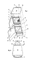
- FIG. 1 A preferred design of an oven 10 according to the invention can be seen in FIG. 1 general, with the oven front open to provide a simplified view of To win inside.
- the one on feet 11 - preferably with a slight recline - standing furnace 10 has a housing 12, the (not designated) furnace walls and the furnace front is limited. It has an upper chamber 14 and a lower one Chamber 34 on, each equipped with a lockable door in a conventional manner are, namely an upper door 13 with a lens 15 and a lower door 43 with viewing window 45.
- the housing 12 is closed off at the top by a cover plate 19, one (not designated) horizontal footprint for heating Vessels, e.g. for a kettle.
- the housing 12 is on the inner walls in the usual way with refractory linings 35 provided (see FIGS. 2 and 5).
- a stovepipe socket on the back 16, which can be manually operated, for example, by means of a lever (not shown)
- Flap 18 is assigned (Fig. 2).
- a flue gas steering plate 17 attached, which serves as a heat shield to protect the smoke tube.
- connection to the rear exhaust ducts 40 or to the uppermost area of the Chamber 14 is separated from flap 18, which has its pivot axis at or near the back wall of the furnace has either sealed or at least partially released.
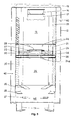
- a sheet metal insert with a raised floor 20, which rests on mounting rails 26 and through Web 23 is diagonally stiffened (Fig. 3 and 4), divides the inner furnace volume, so that its upper part the filling space in the form of the fuel storage and combustion chamber 14 and its lower part forms the afterburning and ash chamber 34.
- One from a fireclay board 22 and a grate 28 existing firing support is all around one Enclosed annular channel 21, which is supplied from the outside with primary and secondary air.
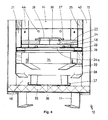
- the fireclay plate 22 which can be divided to facilitate assembly, has one Central passage 24, over which the grate 28 supported by the bracket 27 is located. This connects to the central passage 24 with an annular gap 30, as in particular 2 and 4 can be seen.
- the ring channel 21 has openings 44 in the upper region for the supply of primary air in the chamber 14.
- the double floor 20, one in the middle with the central passage 24th has aligned passage 24a is axially through a narrow space from the the fireclay plate 22 above is separated. In the area of this gap the annular channel 21 has openings 48 for the supply of secondary air.
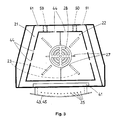
- Fig. 1 provides a view from above into the two chambers 14, 34. Can be seen more clearly 3 and 3a, the lower area of the upper chamber 14 with the furnace, whose design and arrangement is shown in Fig. 4 and 4a, and can be seen furthermore the afterburning chamber 34, which holds a removable ash box 36 has slide rails 37. Both sides of the ash pan 36 are deflection surfaces 38 for the downward flowing flue gas present in the deflection space 46 is deflected to the side above a bottom-side fireclay plate 52 and reaches the stovepipe socket 16 through the exhaust gas ducts 40 (FIG. 2a). you notes that the exhaust channels 40 are arranged on both sides in the housing 12 and can be covered, for example, by curved and / or ribbed outer walls.
- the combustion chamber 14 has fireclay liners 35, which face downwards Ring channel 21 connects. This is fed through a gap 41, which is preferred extends wide across the furnace front. In its upper region, the ring channel 21 has one Number of openings 44 in the form of bores or slots, before which after inside bevelled or inwardly curved folding surfaces can be arranged.
- a control flap 42 on the furnace front which can be actuated by a lever 32 is (Fig. 2, 2a) to finely regulate the supply of primary air and secondary air. In particular by looking at the flow arrows in FIGS.
- the stove 10 has Housing 12 with two chamotte-lined chambers 14, 34.
- a supply air control flap 42 which is common to primary and secondary air and which can be operated by hand lever 32.
- One assigned to her that spanned the entire front Gap 41 feeds an annular channel 21 which the upper combustion chamber 14 in the zone of Firing support 22, 28 encloses.
- the ring channel 21 has in its upper area Openings 44 for primary air, for example at least two holes.
- the disc-shaped Firing support has a fireclay plate 22 above a central passage 24 a grate 28, e.g. a perforated plate parallel to the floor, which with an annular gap 30 to the Raised floor 20 connects, the passage 24a preferably with the plate passage 24 is the same shape.
- the ring channel 21 is preferably integrated into the furnace walls by directly connected to fireclay liners 35 flush.
- Exhaust ducts arranged on the side 40 in the form of long flue gas flues enclose at least partial areas of the ring channel 21.
- the side surfaces of the stove 10 can be aesthetically pleasing and e.g. can also be designed with ribs so that the remaining useful heat is as direct as possible to the surroundings leave.
- Tertiary air can be supplied below the raised floor 20, e.g. about Throttle branches (not shown) from the ring channel 21.
Landscapes
- Engineering & Computer Science (AREA)
- Chemical & Material Sciences (AREA)
- Combustion & Propulsion (AREA)
- Mechanical Engineering (AREA)
- General Engineering & Computer Science (AREA)
- Solid-Fuel Combustion (AREA)
- Crucibles And Fluidized-Bed Furnaces (AREA)
Abstract
Description
- Fig. 1
- eine schematisierte Schrägansicht eines erfindungsgemäßen Ofens mit geöffneten Türen,
- Fig. 1a
- eine Draufsicht auf den Ofen von Fig. 1,
- Fig. 2
- einen Seiten-Längsschnitt durch die Ofenmitte quer zur Rückseite,
- Fig. 2a
- einen Seiten-Längsschnitt entsprechend Fig. 2 mit schematisiert eingezeichneten Strömungsverläufen,
- Fig. 3
- eine Schräg-Einsicht von oben in den Feuerungsraum des Ofens von Fig. 1,
- Fig. 3a
- eine Schräg-Einsicht entsprechend Fig. 3 mit schematisiert eingezeichneten Strömungsverläufen,
- Fig. 4
- einen Teil-Längsschnitt durch die Ofenmitte parallel zur Rückseite,
- Fig. 4a
- einen Teil-Längsschnitt entsprechend Fig. 4 mit schematisiert eingezeichneten Strömungsverläufen und
- Fig. 5
- einen Längsschnitt entsprechend Fig. 4 über die ganze Ofenhöhe.
- 10
- Ofen
- 11
- Füße
- 12
- Gehäuse
- 13
- obere Tür
- 14
- Brennkammer
- 15
- Sichtscheibe
- 16
- Ofenrohrstutzen
- 17
- Rauchgas-Lenkplatte
- 18
- Klappe
- 19
- Deckplatte
- 20
- Doppelboden
- 21
- Ringkanal
- 22
- Schamottplatte(n)
- 23
- Stege
- 24,24a
- Zentraldurchlässe
- 25
- Einlässe/Spülbohrungen
- 26
- Montageleisten
- 27
- Haltewinkel
- 28
- Rost
- 30
- Ringspalt
- 32
- Hebel
- 34
- Nachbrennraum
- 35
- Schamott-Auskleidung
- 36
- Aschekasten
- 37
- Gleitschienen
- 38
- Umlenkfläche(n)
- 39
- Ascheleitfläche(n)
- 40
- Abgaskanäle
- 41
- Frontspalt
- 42
- Regelklappe
- 43
- untere Tür
- 44
- Primärluft-Öffnungen
- 45
- Sichtscheibe
- 46
- Umlenkraum
- 48
- Sekundärluft-Bohrungen
- 50
- Düsen
- 51
- einstellbare Öffnungen
- 52
- Schamottplatte
Claims (18)
- Ofen für Festbrennstoffe, insbesondere Holz, mit einem Gehäuse (12), das eine schamottausgekleidete Brennstoffvorrats- und Brennkammer (14) sowie nahe dieser mündende Zuluft- und Abgaskanäle (21; 40) aufweist, mit einem scheibenoder plattenförmigen Feuerungsträger (22, 28), dessen unterem Bereich eine Sekundärluft-Zufuhr (48) zugeordnet ist und der an einem Zentraldurchlaß (24) über einen Ringspalt (30) mit einer nachgeordneten Nachbrenn- und Aschekammer (34) strömungsverbunden ist, dadurch gekennzeichnet, daß Öffnungen (44, 48) für die Zufuhr von Primär- und Sekundärluft zwischen den Kammern (14, 34) vorhanden sind und daß ein Luftzufuhr-Ringkanal (21) den im unteren Bereich der Brennkammer (14) zentral angeordneten Feuerungsträger (22, 28) umschließt.
- Ofen nach Anspruch 1, dadurch gekennzeichnet, daß im Bereich eines unterhalb des Feuerungsträgers (22, 28) befindlichen, mit einem Zentraldurchlaß (24a) versehenen Doppelbodens (20) Öffnungen (48) zur Zufuhr von Sekundärluft in die Nachbrennkammer (34) vorhanden sind.
- Ofen nach Anspruch 1 oder 2, dadurch gekennzeichnet, daß an der Ofen-Frontseite ein Spalt (41), wenigstens ein Schlitz und/oder eine Reihe beabstandeter Öffnungen (25) vorhanden ist.
- Ofen nach einem der Ansprüche 1 bis 3, dadurch gekennzeichnet, daß eine gemeinsame Zuluft-Regelklappe (42) vorzugsweise im Bereich der Ofen-Frontseite angeordnet ist.
- Ofen nach einem der Ansprüche 1 bis 4, dadurch gekennzeichnet, daß an einer oder jeder Ofenseite in Umfangsabständen wenigstens zwei Ringkanal-Öffnungen (44) für Primärluft angeordnet sind.
- Ofen nach einem der Ansprüche 1 bis 5, dadurch gekennzeichnet, daß die Öffnungen (48) für Sekundärluft als Ringkanal-Radialdurchlässe ausgebildet sind.
- Ofen nach Anspruch 6, dadurch gekennzeichnet, daß die Radialdurchlässe (48) in Form je einer Bohrung oder Aussparung im Mittelbereich von wenigstens zwei Seitenbegrenzungen der Brennkammer (14) ausgebildet sind.
- Ofen nach einem der Ansprüche 1 bis 7, dadurch gekennzeichnet, daß der Ringkanal (21) eine Schamott-Platte (22) umschließt, die den Feuerungsträger (22, 28) oberhalb des Zentraldurchlasses (24) abstützt.
- Ofen wenigstens nach den Ansprüchen 2 und 8, dadurch gekennzeichnet, daß die Öffnungen (48) für Sekundärluft im axialen Zwischenraum zwischen der Schamott-Platte (22) und dem darunter angeordneten Doppelboden (20) münden.
- Ofen nach einem der Ansprüche 2 bis 9, dadurch gekennzeichnet, daß der Feuerungsträger (22) oberhalb des Zentraldurchlasses (24) einen bodenparallelen Rost (28) aufweist, an welchen zum Doppelboden (20) hin ein Ringspalt (30) anschließt.
- Ofen nach Anspruch 10, dadurch gekennzeichnet, daß der Rost (28) mit dem Zentraldurchlaß (24) formähnlich oder formgleich ist.
- Ofen nach einem der Ansprüche 1 bis 11, dadurch gekennzeichnet, daß insbesondere an der Rückseite des Ofens (10) Öffnungen für Minimallast-Zuluft vorhanden sind, beispielsweise düsenförmige Radialdurchlässe (50), Bohrungen (51) mit einstellbarer Weite u.dgl., die nahe am Doppelboden (20) oder direkt in den Ringkanal (21) münden.
- Ofen nach einem der Ansprüche 1 bis 12, dadurch gekennzeichnet, daß der Ringkanal (21) in die Ofenwandungen integriert ist, indem er unmittelbar an Schamott-Auskleidungen (35) bündig oder formgleich anschließt.
- Ofen nach einem der Ansprüche 1 bis 13, dadurch gekennzeichnet, daß die Kammern (14, 34), der Ringkanal (21) und der Doppelboden (20) sich zur Vorderseite des Ofens (10) hin erweitern, bevorzugt in Trapezform.
- Ofen nach einem der Ansprüche 1 bis 14, dadurch gekennzeichnet, daß die an Ofen-Seitenwänden angeordneten Abgaskanäle (40) zumindest Teilbereiche des Ringkanals (21) umschließen.
- Ofen nach einem der Ansprüche 1 bis 15, dadurch gekennzeichnet, daß unterhalb des Doppelbodens (20) Tertiärluft zuführbar ist, insbesondere über Drossel-Abzweigungen vom Ringkanal (21).
- Ofen nach einem der Ansprüche 1 bis 16, dadurch gekennzeichnet, daß der Rauchgas-Weg umsteuerbar ist, beispielweise mittels einer Klappe (18) im Ofenrohrstutzen (16).
- Ofen nach einem der Ansprüche 1 bis 17, dadurch gekennzeichnet, daß das Öffnen der Brennkammertür (13) automatisch eine Umsteuerung der Gasführung bewirkt.
Applications Claiming Priority (2)
| Application Number | Priority Date | Filing Date | Title |
|---|---|---|---|
| DE20203110U DE20203110U1 (de) | 2002-02-27 | 2002-02-27 | Ofen für Festbrennstoffe |
| DE20203110U | 2002-02-27 |
Publications (3)
| Publication Number | Publication Date |
|---|---|
| EP1340943A2 true EP1340943A2 (de) | 2003-09-03 |
| EP1340943A3 EP1340943A3 (de) | 2006-07-05 |
| EP1340943B1 EP1340943B1 (de) | 2009-08-05 |
Family
ID=7968360
Family Applications (1)
| Application Number | Title | Priority Date | Filing Date |
|---|---|---|---|
| EP03002816A Expired - Lifetime EP1340943B1 (de) | 2002-02-27 | 2003-02-07 | Ofen für Festbrennstoffe |
Country Status (3)
| Country | Link |
|---|---|
| EP (1) | EP1340943B1 (de) |
| AT (1) | ATE438831T1 (de) |
| DE (2) | DE20203110U1 (de) |
Cited By (7)
| Publication number | Priority date | Publication date | Assignee | Title |
|---|---|---|---|---|
| DE102009012905B3 (de) * | 2009-03-12 | 2010-01-21 | Global Mind Network Gmbh | Verfahren zur Regelung der Leistung eines Festbrennstoffofens und Ofen mit einer entsprechenden Leistungsregelung |
| DE102013020398A1 (de) | 2012-12-10 | 2014-06-12 | Dbfz Deutsches Biomasseforschungszentrum Gemeinnützige Gmbh | Brennraum, Brennofen, Verfahren und Nachrüstsatz |
| EP2975322A1 (de) * | 2014-07-17 | 2016-01-20 | swissphlox gmbh | Vorrichtung zum Verbrennen von festen Brennstoffen |
| DE202016002972U1 (de) | 2015-05-13 | 2016-06-30 | Ls Kamna S.R.O. | Heizofen für feste Brennstoffe mit zwei Brennkammern |
| ITUB20155563A1 (it) * | 2015-11-13 | 2017-05-13 | Sida Pirolisi S R L S | Stufa pirolitica con camera di combustione perfezionata |
| CZ307820B6 (cs) * | 2015-05-13 | 2019-05-29 | Ls Kamna S.R.O. | Kamna na pevná paliva se dvěma spalovacími komorami |
| EP4089332A1 (de) * | 2021-05-12 | 2022-11-16 | Ulrich Brunner Ofen- und Heiztechnik Gesellschaft für Guß- und Stahlkonstruktionen mbH | Einzelfeuerstätte mit einem wandungselement |
Families Citing this family (3)
| Publication number | Priority date | Publication date | Assignee | Title |
|---|---|---|---|---|
| DE502006006711D1 (de) * | 2006-08-16 | 2010-05-27 | Heinrich Franz Wallnoefer | Wohnraumofen für feste Brennstoffe zur Heizung eines Wohnraums und davon entfernten Räumen sowie zur Heizung von sanitärem Warmwasser |
| DE102013005970A1 (de) | 2012-06-10 | 2013-12-12 | novaTec Elektronik GmbH | Wärmesystem, Wärmesystem mit einem Kaminofen, Anordnung eines Wärmesystems und Verfahren zum Betreiben eines gebäudeinstallierten Wärmesystems |
| CA2886781A1 (en) * | 2012-10-26 | 2014-05-01 | Neal Alexander BOWERS | Wood fuelled heating stove |
Citations (3)
| Publication number | Priority date | Publication date | Assignee | Title |
|---|---|---|---|---|
| EP0124945A2 (de) | 1983-05-06 | 1984-11-14 | Van der Voort, Eduard Thomas Jacobus | Wärmeerzeuger |
| FR2558241A1 (fr) | 1984-01-18 | 1985-07-19 | Tabel Rene | Chaudiere a bois comportant une chambre de prechauffage du comburant |
| DE3935846C2 (de) | 1989-10-27 | 1991-08-14 | Rolf Specht Stahl- Und Apparatebau, 3559 Hatzfeld, De |
Family Cites Families (2)
| Publication number | Priority date | Publication date | Assignee | Title |
|---|---|---|---|---|
| US327650A (en) * | 1885-10-06 | Heating-stove | ||
| FR1016208A (fr) * | 1950-04-12 | 1952-11-05 | Morvan Ets | Appareils de chauffage |
-
2002
- 2002-02-27 DE DE20203110U patent/DE20203110U1/de not_active Expired - Lifetime
-
2003
- 2003-02-07 EP EP03002816A patent/EP1340943B1/de not_active Expired - Lifetime
- 2003-02-07 DE DE50311767T patent/DE50311767D1/de not_active Expired - Lifetime
- 2003-02-07 AT AT03002816T patent/ATE438831T1/de active
Patent Citations (4)
| Publication number | Priority date | Publication date | Assignee | Title |
|---|---|---|---|---|
| EP0124945A2 (de) | 1983-05-06 | 1984-11-14 | Van der Voort, Eduard Thomas Jacobus | Wärmeerzeuger |
| FR2558241A1 (fr) | 1984-01-18 | 1985-07-19 | Tabel Rene | Chaudiere a bois comportant une chambre de prechauffage du comburant |
| EP0152317A1 (de) | 1984-01-18 | 1985-08-21 | René Tabel | Heizkessel für Holz mit einer Vorheizkammer für den Brennstoff |
| DE3935846C2 (de) | 1989-10-27 | 1991-08-14 | Rolf Specht Stahl- Und Apparatebau, 3559 Hatzfeld, De |
Cited By (8)
| Publication number | Priority date | Publication date | Assignee | Title |
|---|---|---|---|---|
| DE102009012905B3 (de) * | 2009-03-12 | 2010-01-21 | Global Mind Network Gmbh | Verfahren zur Regelung der Leistung eines Festbrennstoffofens und Ofen mit einer entsprechenden Leistungsregelung |
| EP2228603A2 (de) | 2009-03-12 | 2010-09-15 | Global Mind Network GmbH | Verfahren zur Regelung der Leistung eines Festbrennstoffofens und Ofen mit einer entsprechenden Leistungsregelung |
| DE102013020398A1 (de) | 2012-12-10 | 2014-06-12 | Dbfz Deutsches Biomasseforschungszentrum Gemeinnützige Gmbh | Brennraum, Brennofen, Verfahren und Nachrüstsatz |
| EP2975322A1 (de) * | 2014-07-17 | 2016-01-20 | swissphlox gmbh | Vorrichtung zum Verbrennen von festen Brennstoffen |
| DE202016002972U1 (de) | 2015-05-13 | 2016-06-30 | Ls Kamna S.R.O. | Heizofen für feste Brennstoffe mit zwei Brennkammern |
| CZ307820B6 (cs) * | 2015-05-13 | 2019-05-29 | Ls Kamna S.R.O. | Kamna na pevná paliva se dvěma spalovacími komorami |
| ITUB20155563A1 (it) * | 2015-11-13 | 2017-05-13 | Sida Pirolisi S R L S | Stufa pirolitica con camera di combustione perfezionata |
| EP4089332A1 (de) * | 2021-05-12 | 2022-11-16 | Ulrich Brunner Ofen- und Heiztechnik Gesellschaft für Guß- und Stahlkonstruktionen mbH | Einzelfeuerstätte mit einem wandungselement |
Also Published As
| Publication number | Publication date |
|---|---|
| DE20203110U1 (de) | 2002-05-08 |
| EP1340943B1 (de) | 2009-08-05 |
| ATE438831T1 (de) | 2009-08-15 |
| DE50311767D1 (de) | 2009-09-17 |
| EP1340943A3 (de) | 2006-07-05 |
Similar Documents
| Publication | Publication Date | Title |
|---|---|---|
| DE3787255T2 (de) | Gas-Kaminofen mit unmittelbarer Luftzufuhr. | |
| DE69205356T2 (de) | Feuer mit Gasbeheizung. | |
| DE1915359A1 (de) | Backofen | |
| EP1340943B1 (de) | Ofen für Festbrennstoffe | |
| US5413089A (en) | Wood and coal burning stove | |
| DE19646525C1 (de) | Vergaserheizkessel für feste Brennstoffe, insbesondere für Holz | |
| AT402850B (de) | Ofen | |
| DE202011000775U1 (de) | Brennkammereinsatz | |
| DE4204163C2 (de) | Ofen zum Verbrennen fester Brennstoffe, insbesondere Kaminofen | |
| AT409892B (de) | Heizeinrichtung für feste brennstoffe, insbesondere kompaktofen bzw. kamineinsatz | |
| DE3705153C2 (de) | ||
| DE4012363C2 (de) | Vorrichtung zum Verbrennen fester Brennstoffe, insbesondere Holz | |
| EP1890092B1 (de) | Wohnraumofen für feste Brennstoffe zur Heizung eines Wohnraums und davon entfernten Räumen sowie zur Heizung von sanitärem Warmwasser | |
| DE2812962C2 (de) | Heizofen für Holz | |
| DE3927378C2 (de) | ||
| DE4329425A1 (de) | Brennkammer zur Holzverbrennung | |
| DE3935846A1 (de) | Ofen fuer festbrennstoffe | |
| DE102006032497B4 (de) | Holzofen | |
| DE3927803C2 (de) | Heizvorrichtung für feste Brennstoffe, insbesondere Kachelofeneinsatz | |
| DE3024680C2 (de) | Herd für feste Brennstoffe als Dauerbrenner- oder Heizungsherd | |
| DE19531821A1 (de) | Vergaserheizkessel für feste Brennstoffe, insbesondere für Holz | |
| AT505770B1 (de) | Holzofen | |
| DE3902091A1 (de) | Kachelofen-heizeinsatz | |
| DE8712826U1 (de) | Ofen für verschiedenartige feste Brennstoffe | |
| DE3429268A1 (de) | Verbrennungseinrichtung |
Legal Events
| Date | Code | Title | Description |
|---|---|---|---|
| PUAI | Public reference made under article 153(3) epc to a published international application that has entered the european phase |
Free format text: ORIGINAL CODE: 0009012 |
|
| AK | Designated contracting states |
Kind code of ref document: A2 Designated state(s): AT BE BG CH CY CZ DE DK EE ES FI FR GB GR HU IE IT LI LU MC NL PT SE SI SK TR |
|
| AX | Request for extension of the european patent |
Extension state: AL LT LV MK RO |
|
| PUAL | Search report despatched |
Free format text: ORIGINAL CODE: 0009013 |
|
| AK | Designated contracting states |
Kind code of ref document: A3 Designated state(s): AT BE BG CH CY CZ DE DK EE ES FI FR GB GR HU IE IT LI LU MC NL PT SE SI SK TR |
|
| AX | Request for extension of the european patent |
Extension state: AL LT LV MK RO |
|
| 17P | Request for examination filed |
Effective date: 20060624 |
|
| 17Q | First examination report despatched |
Effective date: 20061124 |
|
| AKX | Designation fees paid |
Designated state(s): AT BE BG CH CY CZ DE DK EE ES FI FR GB GR HU IE IT LI LU MC NL PT SE SI SK TR |
|
| GRAP | Despatch of communication of intention to grant a patent |
Free format text: ORIGINAL CODE: EPIDOSNIGR1 |
|
| GRAS | Grant fee paid |
Free format text: ORIGINAL CODE: EPIDOSNIGR3 |
|
| GRAA | (expected) grant |
Free format text: ORIGINAL CODE: 0009210 |
|
| AK | Designated contracting states |
Kind code of ref document: B1 Designated state(s): AT BE BG CH CY CZ DE DK EE ES FI FR GB GR HU IE IT LI LU MC NL PT SE SI SK TR |
|
| REG | Reference to a national code |
Ref country code: GB Ref legal event code: FG4D Free format text: NOT ENGLISH |
|
| REG | Reference to a national code |
Ref country code: CH Ref legal event code: EP |
|
| REG | Reference to a national code |
Ref country code: IE Ref legal event code: FG4D |
|
| REF | Corresponds to: |
Ref document number: 50311767 Country of ref document: DE Date of ref document: 20090917 Kind code of ref document: P |
|
| PG25 | Lapsed in a contracting state [announced via postgrant information from national office to epo] |
Ref country code: SE Free format text: LAPSE BECAUSE OF FAILURE TO SUBMIT A TRANSLATION OF THE DESCRIPTION OR TO PAY THE FEE WITHIN THE PRESCRIBED TIME-LIMIT Effective date: 20090805 Ref country code: FI Free format text: LAPSE BECAUSE OF FAILURE TO SUBMIT A TRANSLATION OF THE DESCRIPTION OR TO PAY THE FEE WITHIN THE PRESCRIBED TIME-LIMIT Effective date: 20090805 Ref country code: ES Free format text: LAPSE BECAUSE OF FAILURE TO SUBMIT A TRANSLATION OF THE DESCRIPTION OR TO PAY THE FEE WITHIN THE PRESCRIBED TIME-LIMIT Effective date: 20091116 |
|
| PG25 | Lapsed in a contracting state [announced via postgrant information from national office to epo] |
Ref country code: SI Free format text: LAPSE BECAUSE OF FAILURE TO SUBMIT A TRANSLATION OF THE DESCRIPTION OR TO PAY THE FEE WITHIN THE PRESCRIBED TIME-LIMIT Effective date: 20090805 |
|
| REG | Reference to a national code |
Ref country code: IE Ref legal event code: FD4D |
|
| PG25 | Lapsed in a contracting state [announced via postgrant information from national office to epo] |
Ref country code: PT Free format text: LAPSE BECAUSE OF FAILURE TO SUBMIT A TRANSLATION OF THE DESCRIPTION OR TO PAY THE FEE WITHIN THE PRESCRIBED TIME-LIMIT Effective date: 20091205 Ref country code: BG Free format text: LAPSE BECAUSE OF FAILURE TO SUBMIT A TRANSLATION OF THE DESCRIPTION OR TO PAY THE FEE WITHIN THE PRESCRIBED TIME-LIMIT Effective date: 20091105 |
|
| PG25 | Lapsed in a contracting state [announced via postgrant information from national office to epo] |
Ref country code: IE Free format text: LAPSE BECAUSE OF FAILURE TO SUBMIT A TRANSLATION OF THE DESCRIPTION OR TO PAY THE FEE WITHIN THE PRESCRIBED TIME-LIMIT Effective date: 20090805 Ref country code: DK Free format text: LAPSE BECAUSE OF FAILURE TO SUBMIT A TRANSLATION OF THE DESCRIPTION OR TO PAY THE FEE WITHIN THE PRESCRIBED TIME-LIMIT Effective date: 20090805 Ref country code: CZ Free format text: LAPSE BECAUSE OF FAILURE TO SUBMIT A TRANSLATION OF THE DESCRIPTION OR TO PAY THE FEE WITHIN THE PRESCRIBED TIME-LIMIT Effective date: 20090805 Ref country code: EE Free format text: LAPSE BECAUSE OF FAILURE TO SUBMIT A TRANSLATION OF THE DESCRIPTION OR TO PAY THE FEE WITHIN THE PRESCRIBED TIME-LIMIT Effective date: 20090805 |
|
| PG25 | Lapsed in a contracting state [announced via postgrant information from national office to epo] |
Ref country code: SK Free format text: LAPSE BECAUSE OF FAILURE TO SUBMIT A TRANSLATION OF THE DESCRIPTION OR TO PAY THE FEE WITHIN THE PRESCRIBED TIME-LIMIT Effective date: 20090805 |
|
| PLBE | No opposition filed within time limit |
Free format text: ORIGINAL CODE: 0009261 |
|
| STAA | Information on the status of an ep patent application or granted ep patent |
Free format text: STATUS: NO OPPOSITION FILED WITHIN TIME LIMIT |
|
| 26N | No opposition filed |
Effective date: 20100507 |
|
| PG25 | Lapsed in a contracting state [announced via postgrant information from national office to epo] |
Ref country code: GR Free format text: LAPSE BECAUSE OF FAILURE TO SUBMIT A TRANSLATION OF THE DESCRIPTION OR TO PAY THE FEE WITHIN THE PRESCRIBED TIME-LIMIT Effective date: 20091106 |
|
| PGFP | Annual fee paid to national office [announced via postgrant information from national office to epo] |
Ref country code: LU Payment date: 20120222 Year of fee payment: 10 |
|
| PGFP | Annual fee paid to national office [announced via postgrant information from national office to epo] |
Ref country code: MC Payment date: 20120213 Year of fee payment: 10 Ref country code: CH Payment date: 20120221 Year of fee payment: 10 Ref country code: FR Payment date: 20120227 Year of fee payment: 10 |
|
| PGFP | Annual fee paid to national office [announced via postgrant information from national office to epo] |
Ref country code: BE Payment date: 20120329 Year of fee payment: 10 Ref country code: IT Payment date: 20120221 Year of fee payment: 10 |
|
| PGFP | Annual fee paid to national office [announced via postgrant information from national office to epo] |
Ref country code: NL Payment date: 20120228 Year of fee payment: 10 |
|
| PG25 | Lapsed in a contracting state [announced via postgrant information from national office to epo] |
Ref country code: CY Free format text: LAPSE BECAUSE OF FAILURE TO SUBMIT A TRANSLATION OF THE DESCRIPTION OR TO PAY THE FEE WITHIN THE PRESCRIBED TIME-LIMIT Effective date: 20090805 |
|
| PG25 | Lapsed in a contracting state [announced via postgrant information from national office to epo] |
Ref country code: HU Free format text: LAPSE BECAUSE OF FAILURE TO SUBMIT A TRANSLATION OF THE DESCRIPTION OR TO PAY THE FEE WITHIN THE PRESCRIBED TIME-LIMIT Effective date: 20100206 |
|
| PG25 | Lapsed in a contracting state [announced via postgrant information from national office to epo] |
Ref country code: TR Free format text: LAPSE BECAUSE OF FAILURE TO SUBMIT A TRANSLATION OF THE DESCRIPTION OR TO PAY THE FEE WITHIN THE PRESCRIBED TIME-LIMIT Effective date: 20090805 |
|
| PGFP | Annual fee paid to national office [announced via postgrant information from national office to epo] |
Ref country code: AT Payment date: 20120213 Year of fee payment: 10 |
|
| PGFP | Annual fee paid to national office [announced via postgrant information from national office to epo] |
Ref country code: GB Payment date: 20130218 Year of fee payment: 11 |
|
| BERE | Be: lapsed |
Owner name: STAHL- UND APPARATEBAU SPECHT OHG Effective date: 20130228 |
|
| REG | Reference to a national code |
Ref country code: NL Ref legal event code: V1 Effective date: 20130901 |
|
| PG25 | Lapsed in a contracting state [announced via postgrant information from national office to epo] |
Ref country code: MC Free format text: LAPSE BECAUSE OF NON-PAYMENT OF DUE FEES Effective date: 20130228 |
|
| REG | Reference to a national code |
Ref country code: CH Ref legal event code: PL |
|
| REG | Reference to a national code |
Ref country code: AT Ref legal event code: MM01 Ref document number: 438831 Country of ref document: AT Kind code of ref document: T Effective date: 20130228 |
|
| PG25 | Lapsed in a contracting state [announced via postgrant information from national office to epo] |
Ref country code: LI Free format text: LAPSE BECAUSE OF NON-PAYMENT OF DUE FEES Effective date: 20130228 Ref country code: AT Free format text: LAPSE BECAUSE OF NON-PAYMENT OF DUE FEES Effective date: 20130228 Ref country code: NL Free format text: LAPSE BECAUSE OF NON-PAYMENT OF DUE FEES Effective date: 20130901 Ref country code: CH Free format text: LAPSE BECAUSE OF NON-PAYMENT OF DUE FEES Effective date: 20130228 |
|
| REG | Reference to a national code |
Ref country code: FR Ref legal event code: ST Effective date: 20131031 |
|
| PG25 | Lapsed in a contracting state [announced via postgrant information from national office to epo] |
Ref country code: IT Free format text: LAPSE BECAUSE OF NON-PAYMENT OF DUE FEES Effective date: 20130207 |
|
| PG25 | Lapsed in a contracting state [announced via postgrant information from national office to epo] |
Ref country code: FR Free format text: LAPSE BECAUSE OF NON-PAYMENT OF DUE FEES Effective date: 20130228 Ref country code: BE Free format text: LAPSE BECAUSE OF NON-PAYMENT OF DUE FEES Effective date: 20130228 |
|
| GBPC | Gb: european patent ceased through non-payment of renewal fee |
Effective date: 20140207 |
|
| PG25 | Lapsed in a contracting state [announced via postgrant information from national office to epo] |
Ref country code: GB Free format text: LAPSE BECAUSE OF NON-PAYMENT OF DUE FEES Effective date: 20140207 |
|
| PG25 | Lapsed in a contracting state [announced via postgrant information from national office to epo] |
Ref country code: LU Free format text: LAPSE BECAUSE OF NON-PAYMENT OF DUE FEES Effective date: 20130207 |
|
| REG | Reference to a national code |
Ref country code: DE Ref legal event code: R082 Ref document number: 50311767 Country of ref document: DE Representative=s name: FARAGO PATENTANWALTSGESELLSCHAFT MBH, DE |
|
| PGFP | Annual fee paid to national office [announced via postgrant information from national office to epo] |
Ref country code: DE Payment date: 20220428 Year of fee payment: 20 |
|
| REG | Reference to a national code |
Ref country code: DE Ref legal event code: R071 Ref document number: 50311767 Country of ref document: DE |