EP1340679B1 - Formschulter zur Herstellung von Dreiseiten-Siegelrand-Schlauchbeuteln - Google Patents
Formschulter zur Herstellung von Dreiseiten-Siegelrand-Schlauchbeuteln Download PDFInfo
- Publication number
- EP1340679B1 EP1340679B1 EP03003636A EP03003636A EP1340679B1 EP 1340679 B1 EP1340679 B1 EP 1340679B1 EP 03003636 A EP03003636 A EP 03003636A EP 03003636 A EP03003636 A EP 03003636A EP 1340679 B1 EP1340679 B1 EP 1340679B1
- Authority
- EP
- European Patent Office
- Prior art keywords
- film
- channel
- inlet edge
- form shoulder
- flow
- Prior art date
- Legal status (The legal status is an assumption and is not a legal conclusion. Google has not performed a legal analysis and makes no representation as to the accuracy of the status listed.)
- Expired - Lifetime
Links
- 238000004519 manufacturing process Methods 0.000 title claims description 4
- 238000013459 approach Methods 0.000 claims description 9
- 230000035515 penetration Effects 0.000 claims description 9
- 239000000945 filler Substances 0.000 claims description 2
- 230000000630 rising effect Effects 0.000 claims description 2
- 239000011888 foil Substances 0.000 description 7
- 238000007789 sealing Methods 0.000 description 7
- 238000013461 design Methods 0.000 description 4
- 239000005022 packaging material Substances 0.000 description 4
- 238000011161 development Methods 0.000 description 3
- 230000018109 developmental process Effects 0.000 description 3
- 238000003801 milling Methods 0.000 description 3
- 238000012549 training Methods 0.000 description 3
- 239000008186 active pharmaceutical agent Substances 0.000 description 2
- 230000006978 adaptation Effects 0.000 description 2
- 230000003628 erosive effect Effects 0.000 description 2
- 238000000465 moulding Methods 0.000 description 2
- 238000004806 packaging method and process Methods 0.000 description 2
- 230000037303 wrinkles Effects 0.000 description 2
- 230000001427 coherent effect Effects 0.000 description 1
- 230000002349 favourable effect Effects 0.000 description 1
- 238000009459 flexible packaging Methods 0.000 description 1
- 238000000034 method Methods 0.000 description 1
- 229920006280 packaging film Polymers 0.000 description 1
- 239000012785 packaging film Substances 0.000 description 1
- 230000008521 reorganization Effects 0.000 description 1
- 238000000926 separation method Methods 0.000 description 1
- 239000003206 sterilizing agent Substances 0.000 description 1
- 235000012773 waffles Nutrition 0.000 description 1
Images


Classifications
-
- B—PERFORMING OPERATIONS; TRANSPORTING
- B65—CONVEYING; PACKING; STORING; HANDLING THIN OR FILAMENTARY MATERIAL
- B65B—MACHINES, APPARATUS OR DEVICES FOR, OR METHODS OF, PACKAGING ARTICLES OR MATERIALS; UNPACKING
- B65B9/00—Enclosing successive articles, or quantities of material, e.g. liquids or semiliquids, in flat, folded, or tubular webs of flexible sheet material; Subdividing filled flexible tubes to form packages
- B65B9/10—Enclosing successive articles, or quantities of material, in preformed tubular webs, or in webs formed into tubes around filling nozzles, e.g. extruded tubular webs
- B65B9/20—Enclosing successive articles, or quantities of material, in preformed tubular webs, or in webs formed into tubes around filling nozzles, e.g. extruded tubular webs the webs being formed into tubes in situ around the filling nozzles
- B65B9/213—Enclosing successive articles, or quantities of material, in preformed tubular webs, or in webs formed into tubes around filling nozzles, e.g. extruded tubular webs the webs being formed into tubes in situ around the filling nozzles the web having intermittent motion
-
- B—PERFORMING OPERATIONS; TRANSPORTING
- B65—CONVEYING; PACKING; STORING; HANDLING THIN OR FILAMENTARY MATERIAL
- B65B—MACHINES, APPARATUS OR DEVICES FOR, OR METHODS OF, PACKAGING ARTICLES OR MATERIALS; UNPACKING
- B65B9/00—Enclosing successive articles, or quantities of material, e.g. liquids or semiliquids, in flat, folded, or tubular webs of flexible sheet material; Subdividing filled flexible tubes to form packages
- B65B9/10—Enclosing successive articles, or quantities of material, in preformed tubular webs, or in webs formed into tubes around filling nozzles, e.g. extruded tubular webs
- B65B9/20—Enclosing successive articles, or quantities of material, in preformed tubular webs, or in webs formed into tubes around filling nozzles, e.g. extruded tubular webs the webs being formed into tubes in situ around the filling nozzles
- B65B9/22—Forming shoulders; Tube formers
-
- B—PERFORMING OPERATIONS; TRANSPORTING
- B65—CONVEYING; PACKING; STORING; HANDLING THIN OR FILAMENTARY MATERIAL
- B65B—MACHINES, APPARATUS OR DEVICES FOR, OR METHODS OF, PACKAGING ARTICLES OR MATERIALS; UNPACKING
- B65B2210/00—Specific aspects of the packaging machine
- B65B2210/02—Plurality of alternative input or output lines or plurality of alternative packaging units on the same packaging line for improving machine flexibility
-
- B—PERFORMING OPERATIONS; TRANSPORTING
- B65—CONVEYING; PACKING; STORING; HANDLING THIN OR FILAMENTARY MATERIAL
- B65B—MACHINES, APPARATUS OR DEVICES FOR, OR METHODS OF, PACKAGING ARTICLES OR MATERIALS; UNPACKING
- B65B2220/00—Specific aspects of the packaging operation
- B65B2220/22—Interconnected packages concurrently produced from the same web, the packages not being separated from one another
Definitions
- the invention relates to a shaped shoulder for the production of Three-sided sealed-edge tubular bags according to the preamble of Claim 1.
- a shape shoulder of the type mentioned is known and in Use for which, however, no printed proof can be provided.
- Deviating from the introductory mentioned form shoulder is the shawl collar A special foil guide surfaces according to US-A-6,006,501 Subsequent molding, one over his has a relatively short length of constant cross section, which roughly corresponds to an eight. This will be supplementary also in relation to the above-mentioned US-A-6,006,501 significantly older and prepublished DE-A-27 30 169 and DE-A-29 32 236.
- the invention is based on the shape of the shoulder of the beginning mentioned type, accordingly the task underlying this to improve that already from the emergence of the film web on the form shoulder, excluding those immediately downstream Fittings are taken care of already a gradual adaptation of the film web to that for longitudinal sealing typical end cross section of the film tube he follows.
- Such the asymptotic approximation is on an imaginary longitudinal median plane sourced through the canal.
- Concerning. the asymptotic Approach "also from the channel side areas" is on it noted that the width of the channel is unaffected remains, i.e. the width of the flow channel in the form shoulder stays the same from top to bottom.
- the invention Pass-through channel has, so to speak, as Imagine the wide-squeezed funnel, the two edge areas however, have no convergence oriented towards discontinuation.
- the Foil leading edge in plan view in the direction of the foil passage slightly convex penetration curve of the surface the rear wall and the film inlet surface.
- This for Film inlet edge leading film inlet surface points to the film inlet edge sidewall regions converging and becoming wider on that steadily rising from the inflow surface merge into the two side, sloping foil guide surfaces.
- the leading edge experiences one Reorganization into a weakly curved penetration curve.
- Such a form has been shown the leading edge already in this area to a better one Adaptation of the incoming film to the cross-sectional shape of the Foil flow channel in the form shoulder.
- the convex extension becomes weak the edge areas of the incoming film web are drawn in a little more. This improves the edge areas of the film web to the strongly concave side edge curvatures of the flow channel adapts in the area of the two form or filler tubes extend and in their area so far with straight extension to observe certain wrinkles on the film leading edge were.
- An embodiment can also consist in that the seen from the front wedge-shaped cutout and the slit in relation arranged asymmetrically on the center of the film leading edge are. This leads to a double hose in which one has a larger cross section than the other.
- the shape shoulder with its film passageway and the channel covers formed from a block in which the Flow channel with its inner wall contour according to the invention is formed with suitable means (milling / eroding).
- suitable means milling / eroding.
- the Shaped parts are those on the back wall of the film strip applied film strip edges with the back wall in known Longitudinally sealed.
- the shorter word Former is used instead of the shape shoulder.
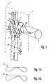
- 1 schematically shows the arrangement of the former 1 in a packaging machine, indicated only by dashed lines, in which the film strip FS drawn off from a roll R is converted into a double tube DS by means of the former 1.
- 100 is a longitudinal sealing tool and 101 is a transverse sealing tool.
- the clocked deduction of the film strip FS from the roll R is caused by the up and down movable cross sealing tools 101. From the shaped tubes 13 and the curved side walls 12 a passage gap 20 is formed for the film.
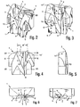
- the former consists of a reference to Fig.2 and Fig.3 block-shaped fitting 1, in which there is an inside up and down open film flow channel 2 extends.
- the formers after the Fig.2 and Fig.3 differ only in that with the 2 a symmetrical double hose (see Fig. 1A) and with the former according to Fig. 3 an asymmetrical double hose (Fig. 1B) is generated.
- the channel 2 extends from the upper film leading edge 3 Rear wall 4 of the channel 2 up to the outlet opening 5 (see Fig. 7) of channel 2.
- This channel 2 is forward through two channel front walls 6 limited.
- the steadily at the film leading edge 3 Define the subsequent shape edges 7 of the front walls 6 a wedge-shaped, in the direction of film P (see Fig.1) oriented section 9, which merges into a slot 8 bez. expires.
- the channel front walls 6 are on the outside in the form of a shawl collar, which ends at slot 8 Foil guiding surfaces 10 are formed, which continuously correspond to corresponding Foil guide surfaces 10 'on the main body of the former 1 connect.
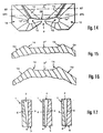
- Fig. 17 Three possibilities, which is illustrated very schematically in Fig. 17 is.
- the front walls approach 6 of the vertical back wall 4.
- the rear wall 4 approaches the vertical front walls 6 on and in the right example, which is preferred, are approaching the rear wall 4 and the front walls 6 together towards each other.
- the former 1 is with its film passageway 2 and Channel front walls 6, as shown in FIGS. 1, 2, from one Block formed, for example by means of CNC milling or by means of an erosion process accordingly program-controlled and so far can be produced identically reproducibly.
- the block 7 advantageous by a in the direction of flow P and 3 parallel to the film leading edge, vertical Extension plane E '(see Fig. 8 to 11) under training separate channel front walls 6 divided. In terms of such a division is referred in particular to FIG. 8.
- the aforementioned manufacturing methods make it possible without problems and advantageously, who touched it when it passed through the film web Areas (film guide surfaces 10, 10 ') of the former at least in the run-up area 13 of the block 7 with a nub or to provide waffle iron-like surface structure OS that is indicated in only a partial area in FIG.
- Structuring is sufficient for depths in the tenths of a millimeter range sufficient sterilizing agent between the film guide surfaces 10,10 'and the film strip FS arrive provided the tubular bag under sterile conditions must be manufactured, which is usually the case.
- the film leading edge 3 in plan view a slightly convex in the direction of the film passageway 2
- Penetration curve DK is made up of the penetrations the surface of the rear wall 4 and the film inlet surface 3 '.
- the film inlet surface 3 ' has, as from the top view 14, converging towards the penetration curve DK and widening sidewall areas 14 that steadily increasing from the surface 3 'into the film guide surfaces 10 'as shown in sections XV-XV and XVI-XVI 15, 16 is shown.
- the previously described ramp 4 ' is of course also present in this embodiment.
- This design of the film leading edge 3 in the form of a convex curve penetration curve DK according to the present Invention is achieved that it is already in this area of Formers 1 for a better adjustment of the incoming film strip FS to the cross-sectional shape of the film flow channel 4 is coming.
- the edge areas of the incoming film are namely this pulls in a little more, which makes the film better to the strongly concave side edge curvatures of the flow channel 2 adapts. Otherwise occurring with a straight film leading edge 3 certain wrinkles are thereby avoided or greatly reduced.
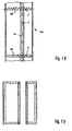
- FIG. 18 is a double bag strand DS with its longitudinal sealing seam LS and its transverse sealing seams QS shows how it works in a former Fig. 3.4 results.
- Fig. 19 finally represents two unequal widths Pouches that appear after separation along the dashed line Lines T from the strand according to Fig. 18 result.
Landscapes
- Engineering & Computer Science (AREA)
- Mechanical Engineering (AREA)
- Containers And Plastic Fillers For Packaging (AREA)
- Bag Frames (AREA)
Description
Es zeigt
- FIG. 1
- schematisch die Anordnung der Formschulter an einer nur gestrichelt angedeuteten Schlauchbeutelverpackungsmaschine;
- FIG. 1A
- im Schnitt einen mit einer Formschulter gemäß FIG.2 hergestellten Doppelschlauch;
- FIG.1B
- im Schnitt einen mit einer Formschulter gemäß FIG.3 hergestellten Doppelschlauch;
- FIG.2
- perspektivisch eine symmetrische Ausführungsform der Formschulter;
- FIG.3
- perspektivisch eine asymmetrische Ausführungsform der Formschulter;
- FIG.4
- die Formschulter nach Fig.3 in Vorderansicht;
- FIG.5
- die Formschulter nach Fig.4 in Seitenansicht;
- FIG.6
- die Formschulter nach Fig.4 in Ansicht von oben;
- FIG.7
- die Formschulter nach Fig.4 in Ansicht von unten;
- FIG.8
- die Formschulter nach Fig.4 in Ansicht von unten und in besonderer Ausführungsform;
- FIG.9-11
- Schnitte durch die Formschulter längs der Linien IX-IX, X-X, XI-XI in Fig.4;
- FIG.12
- eine besondere Ausführungsform der Formschulter;
- FIG.12A
- schematisch die Vorderansicht einer Schlauchbeutel-Maschine mit vier in Reihe angeordneten Formern;
- FIG.13
- eine weitere und bevorzugte Ausführungsform der Formschulter;
- FIG.14
- eine Draufsicht auf die Formschulter nach FIG.13;
- FIG.15
- stark vergrößert einen Schnitt durch die Formschulter längs Linie XV-XV in FIG.14;
- FIG.16
- stark vergrößert einen Schnitt durch die Formschulter längs Linie XVI-XVI in FIG.14;
- FIG.17
- schematisch drei Schnitte durch den Kanal der Formschulter senkrecht zur Rückwand zur Darstellung des Prinzips unterschiedlicher Annäherungen der Rückwand und der Vorderwände der Formschulter;
- FIG.18
- den mit dem Formschulter gemäß FIG.3 oder nFig. 13 gebildeten Doppelschlauch in Seitenansicht und
- Fig.19
- einen Schnitt durch den Doppelschlauch gemäß Fig.18 längs Linie XVIII-XVIII in FIG.17.
Fig. 1 zeigt schematisch die Anordnung des Formers 1 in einer nur gestrichelt angedeuteten Verpackungsmaschine, in der mittels des Formers 1 der von einer Rolle R abgezogene Folienstreifen FS in einen Doppelschlauch DS umgewandelt wird. Mit 100 ist ein Längssiegelwerkzeug und mit 101 ein Quersiegelwerkzeug bezeichnet. Form- und Füllrohre 13, die auch in Fig. 10 mit angedeutet sind, durchgreifen den Kanal 2 im Former 1.
Claims (9)
- Formschulter zur Herstellung von Dreiseiten-Siegelrand-Schlauchbeuteln, bestehend aus einem Formstück (1), in dem sich innen ein oben und unten offener, von Form und/oder Füllrohren (13) durchgriffener Foliendurchlaufkanal(2) erstreckt, von dessen oberer Folieneinlaufkante (3) aus sich die Rückwand (4) des Kanales (2) bis zur Auslauföffnung (5) des Kanales (2) erstreckt, der nach vorn durch zwei Kanalabdeckungen (6) begrenzt ist, deren sich stetig an die Folieneinlaufkante (3) anschließenden Formkanten (7) einen in einen in Foliendurchlaufrichtung orientierten Schlitz (8) übergehenden keilförmigen Ausschnitt (9) definieren, wobei die Kanalabdeckungen (6) aussenseitig in Form schalkragenartiger, am Schlitz (8) auslaufender Folienleitflächen (10) ausgebildet sind,
dadurch gekennzeichnet, daß von der Folieneinlaufkante (3) und von den Kanalseitenbereichen (12) aus die Rückwand (4) und die Innenflächen (11) der Kanalabdeckungen (6) relativ zueinander zum unteren Ende des Schlitzes (8) hin in Foliendurchlaufrichtung sich asymptotisch annähernd ausgeformt sind. - Formschulter nach Anspruch 1,
dadurch gekennzeichnet, daß in der Rückwand (4) eine im Querschnitt trapezförmige Rampe (4') ausgeformt ist, deren Querschnitte, mit einem O-Querschnitt und einem Bruchteil der Breite der Folieneinlaufkante (3) an dieser ansetzend, sich stetig in Höhe (H) und der Basisbreite (B) bis zum Ende des Schlitzes (8) zunehmend vergrößern. - Formschulter nach Anspruch 1 oder 2,
dadurch gekennzeichnet, daß die Folieneinlaufkante (3) in Draufsicht eine in Richtung Foliendurchlaufkanal (2) schwach konvex gewölbte Durchdringungskurve (DK) der Fläche der Rückwand (4) und der Folienzulauffläche (3') bildet, welche Folienzulauffläche (3') zur Folieneinlaufkante (3) hin konvergierende und breiter werdende Seitenwandbereiche (14) aufweist, die aus der Fläche (3') stetig ansteigend in die beiden seitlich abfallenden Folienleitflächen (10) übergehen. - Formschulter nach einem der Ansprüche 1 bis 3,
dadurch gekennzeichnet, daß der keilförmige Ausschnitt (9) und der Schlitz (8) in Bezug auf die Mitte der Folieneinlaufkante (3) asymmetrisch angeordnet sind. - Formschulter nach einem der Ansprüche 1 bis 4,
dadurch gekennzeichnet, daß die Formschulter mit ihrem Foliendurchlaufkanal (2) und den Kanalabdeckungen (6) aus einem Block (7) gebildet sind. - Formschulter nach Anspruch 5,
dadurch gekennzeichnet, daß der Block (7) durch eine in Durchlaufrichtung und zur Folieneinlaufkante (3) parallele Erstreckungsebene (B') unter Ausbildung separater Kanalabdeckungen (6) geteilt ist. - Formschulter nach Anspruch 5 oder 6,
dadurch gekennzeichnet, daß mehrere Unterteile (BT) der Blöcke (7) zu einer Blockzeile (7') zusammengefaßt und auf diesem die separaten Kanalabdekkungen (6) angeordnet sind. - Formschulter nach Anspruch 7,
dadurch gekennzeichnet, daß bis auf die beiden äußeren Kanalabdeckungen (6) die anderen Kanalabdeckungen paarweise zu jeweils einer Kanalabdeckung (6') zusammengefaßt sind. - Formschulter nach einem der Ansprüche 1 bis 8,
dadurch gekennzeichnet, daß die beim Durchlauf der Folienbahn von dieser berührten Flächen der Formschulter mindestens im Auflaufbereich (13) des Blockes (7) mit einer noppenartigen Oberflächenstruktur (OS) versehen sind.
Applications Claiming Priority (4)
| Application Number | Priority Date | Filing Date | Title |
|---|---|---|---|
| DE10209356 | 2002-03-02 | ||
| DE2002109356 DE10209356A1 (de) | 2002-03-02 | 2002-03-02 | Formschulter zur Herstellung von Dreiseiten-Siegelrand-Schlauchbeuteln |
| DE10217949A DE10217949A1 (de) | 2002-03-02 | 2002-04-22 | Formschulter zur Herstellung von Dreiseiten-Siegelrand- Schlauchbeuteln |
| DE10217949 | 2002-04-22 |
Publications (2)
| Publication Number | Publication Date |
|---|---|
| EP1340679A1 EP1340679A1 (de) | 2003-09-03 |
| EP1340679B1 true EP1340679B1 (de) | 2004-12-08 |
Family
ID=27735699
Family Applications (1)
| Application Number | Title | Priority Date | Filing Date |
|---|---|---|---|
| EP03003636A Expired - Lifetime EP1340679B1 (de) | 2002-03-02 | 2003-02-18 | Formschulter zur Herstellung von Dreiseiten-Siegelrand-Schlauchbeuteln |
Country Status (3)
| Country | Link |
|---|---|
| US (2) | USD481744S1 (de) |
| EP (1) | EP1340679B1 (de) |
| DE (2) | DE10217949A1 (de) |
Families Citing this family (14)
| Publication number | Priority date | Publication date | Assignee | Title |
|---|---|---|---|---|
| WO2004087502A2 (en) * | 2003-03-27 | 2004-10-14 | Swf Companies, Inc. | High-speed continuous action form-fill-seal apparatus |
| DE10319820A1 (de) * | 2003-05-03 | 2004-11-25 | Poly-Clip System Gmbh & Co. Kg | Verfahren zum Herstellen von Portionspackungen in einem Folienschlauch |
| DE102004016500A1 (de) * | 2004-04-03 | 2005-10-20 | Rovema Gmbh | Vertikale Schlauchbeutelmaschine zum Verpacken horizontal ausgerichteter Gegenstandsgruppen |
| DE102007049210B3 (de) * | 2007-10-13 | 2008-10-09 | Mediseal Gmbh | Werkzeug für eine Schlauchbeutelmaschine zum Umformen eines Hüllmaterialstreifens in einen Schlauch |
| US8371094B2 (en) | 2009-10-23 | 2013-02-12 | Frito-Lay North America, Inc. | Method and apparatus for compacting product |
| US9284075B2 (en) * | 2009-10-23 | 2016-03-15 | Frito-Lay North America, Inc. | Apparatus for compacting product and high speed bagmaking |
| US8567165B2 (en) * | 2009-10-23 | 2013-10-29 | Frito-Lay North America, Inc. | Method and apparatus for compacting product |
| DE102009046717A1 (de) * | 2009-11-16 | 2011-05-19 | Robert Bosch Gmbh | Verfahren und Vorrichtung zur Herstellung eines Verpackungsbeutels aus flexiblem Folienmaterial sowie Verpackungsbeutel |
| DE102009053415A1 (de) * | 2009-11-19 | 2011-05-26 | Drut, Henry, Dr. | Verfahren und Vorrichtung zur Herstellung von Schlauchbeuteln |
| CN103569414B (zh) * | 2013-10-23 | 2015-09-09 | 广州市一路高包装机械技术有限公司 | 袋成形装置及包装机 |
| PL3981696T3 (pl) * | 2016-05-05 | 2024-11-18 | Amcor Flexibles North America, Inc. | Owijarka przepływowa z rurą formującą |
| DE102016213087B4 (de) * | 2016-07-18 | 2018-07-05 | Rovema Gmbh | Verfahren zum Betrieb einer Schlauchbeutelmaschine zur Herstellung von Beuteln mit einer Boden-Quernaht und einer davon unterschiedlichen Kopf-Quernaht |
| US10682827B2 (en) * | 2016-08-31 | 2020-06-16 | Winpak Lane, Inc. | Forming station for forming pairs of three side seal pouches |
| US10604283B2 (en) | 2017-05-26 | 2020-03-31 | Frito-Lay North America, Inc. | Former assembly with improved center of gravity |
Family Cites Families (12)
| Publication number | Priority date | Publication date | Assignee | Title |
|---|---|---|---|---|
| US3494265A (en) * | 1968-02-01 | 1970-02-10 | Woodman Co | Package former with multiple elliptical curve |
| US3837138A (en) * | 1973-02-23 | 1974-09-24 | Johns Manville | Method and apparatus for compressing material and enclosing the same in a plastic film |
| DE2730169A1 (de) | 1977-07-04 | 1979-01-11 | Kloeckner Werke Ag | Beutel aus folienmaterial |
| DE2932236A1 (de) | 1979-08-09 | 1981-02-26 | Hassia Verpackung Gmbh | Vorrichtung zum herstellen von dreiseiten-siegelrandbeuteln |
| US4706440A (en) * | 1986-12-09 | 1987-11-17 | Precision Automation Co., Inc. | Method and apparatus for packaging expansile articles |
| USD366995S (en) | 1994-12-02 | 1996-02-13 | W. A. Lane, Inc. | Pair of pouch forming tool jaws |
| USD372037S (en) | 1994-12-22 | 1996-07-23 | W. A. Lane, Inc. | Pair of tool jaws to form salad dressing pouches |
| US6371644B1 (en) | 1997-05-22 | 2002-04-16 | Sealstrip Corp. | Reclosable seal, package, method and apparatus |
| JPH1191729A (ja) * | 1997-09-19 | 1999-04-06 | Shikoku Kakoki Co Ltd | チューブ成形方法と装置及び包装容器製造機械 |
| US6006501A (en) | 1998-03-30 | 1999-12-28 | Winpak Lane, Inc. | Three-sided pouches, machine and method of making |
| JP4094166B2 (ja) * | 1999-04-07 | 2008-06-04 | 株式会社イシダ | 包装システム |
| DE10032551B4 (de) * | 2000-06-28 | 2004-06-03 | Drut, Henry, Dr.-Ing. | Formschulter und Vorrichtung zur Herstellung von längsgeformten Bahnen |
-
2002
- 2002-04-22 DE DE10217949A patent/DE10217949A1/de not_active Ceased
- 2002-08-02 US US29/165,046 patent/USD481744S1/en not_active Expired - Lifetime
-
2003
- 2003-02-18 DE DE2003500185 patent/DE50300185D1/de not_active Expired - Lifetime
- 2003-02-18 EP EP03003636A patent/EP1340679B1/de not_active Expired - Lifetime
- 2003-02-28 US US10/377,467 patent/US6813871B2/en not_active Expired - Lifetime
Also Published As
| Publication number | Publication date |
|---|---|
| US6813871B2 (en) | 2004-11-09 |
| USD481744S1 (en) | 2003-11-04 |
| US20030163979A1 (en) | 2003-09-04 |
| DE10217949A1 (de) | 2003-12-11 |
| EP1340679A1 (de) | 2003-09-03 |
| DE50300185D1 (de) | 2005-01-13 |
Similar Documents
| Publication | Publication Date | Title |
|---|---|---|
| DE69333246T2 (de) | Pumpeinheit für eine Flasche aus Verbundmaterial | |
| EP1340679A1 (de) | Formschulter zur Herstellung von Dreiseiten-Siegelrand-Schlauchbeuteln | |
| DE69600796T2 (de) | Maschine zum Verpacken von Gegenständen in einem, zu einem Schlauch umgeformten, Band | |
| EP1847186B1 (de) | Aufbereitungseinheit zur Aufbereitung mindestens eines Filtertowstreifens für die Herstellung von Filtern für stabförmige Rauchartikel | |
| DE69205000T2 (de) | Verfahren zum herstellen einer zahnärztlichen absaugeinrichtung. | |
| WO2000037245A1 (de) | Vorrichtung zum herstellen von schlauchbeutelpackungen | |
| DE102010042067A1 (de) | Verfahren und Vorrichtung zum Herstellen eines Konturschnitts in einem Blechband | |
| DE4446936A1 (de) | Verfahren und Vorrichtung zur Vorbereitung der Parallelherstellung von Schlauchbeutelpackungen | |
| DE4328259A1 (de) | Verfahren und Maschine zum Herstellen von Zigaretten | |
| DE60201860T2 (de) | Führungsschiene für eine Kettensäge einschliesslich Baumstumpfbehandlung | |
| DE2557380C2 (de) | Verformungswerkzeug für die Herstellung eines gewellten Innenrohres eines doppelwandigen Tropfbewässerungsrohres mit glattwandigem Außenrohr | |
| DE60026069T2 (de) | Verfahren zur gleichzeitigen herstellung von zumindest zwei tropfbewässerungsschläuchen | |
| AT502105B1 (de) | Vorrichtung zum kalibrieren eines extrudierten kunststoffprofils | |
| DE10209356A1 (de) | Formschulter zur Herstellung von Dreiseiten-Siegelrand-Schlauchbeuteln | |
| DE3248322C2 (de) | ||
| DE2932236A1 (de) | Vorrichtung zum herstellen von dreiseiten-siegelrandbeuteln | |
| DE2246976B2 (de) | Zigarettenherstellungsmaschine für einen aus einem Kern und Tabakring bestehenden Strang | |
| EP2764768B1 (de) | Tropfbewässerungsrohr mit Dosierelementen | |
| CH650213A5 (de) | Verfahren und vorrichtung zum herstellen eines behaelters aus thermoplastischem kunststoff und damit hergestellter behaelter. | |
| DE2817621C3 (de) | Füllrohr für Verpackungsmaschinen | |
| DE3602590C2 (de) | ||
| DE3209971C2 (de) | ||
| DE4107905C2 (de) | Herstellverfahren zum Herstellen eines geschlitzten Siebkorbes | |
| EP3551419B1 (de) | Vorrichtung und verfahren zum herstellen von objekten aus einer erstarrenden formmasse mit schiebereinrichtung | |
| DE4338371A1 (de) | Verfahren und Vorrichtung zum Herstellen von Zigaretten |
Legal Events
| Date | Code | Title | Description |
|---|---|---|---|
| PUAI | Public reference made under article 153(3) epc to a published international application that has entered the european phase |
Free format text: ORIGINAL CODE: 0009012 |
|
| AK | Designated contracting states |
Kind code of ref document: A1 Designated state(s): AT BE BG CH CY CZ DE DK EE ES FI FR GB GR HU IE IT LI LU MC NL PT SE SI SK TR |
|
| AX | Request for extension of the european patent |
Extension state: AL LT LV MK RO |
|
| 17P | Request for examination filed |
Effective date: 20030807 |
|
| 17Q | First examination report despatched |
Effective date: 20030909 |
|
| GRAP | Despatch of communication of intention to grant a patent |
Free format text: ORIGINAL CODE: EPIDOSNIGR1 |
|
| GRAS | Grant fee paid |
Free format text: ORIGINAL CODE: EPIDOSNIGR3 |
|
| AKX | Designation fees paid |
Designated state(s): DE GB IT SE |
|
| GRAA | (expected) grant |
Free format text: ORIGINAL CODE: 0009210 |
|
| AK | Designated contracting states |
Kind code of ref document: B1 Designated state(s): DE GB IT SE |
|
| REG | Reference to a national code |
Ref country code: GB Ref legal event code: FG4D Free format text: NOT ENGLISH |
|
| REG | Reference to a national code |
Ref country code: SE Ref legal event code: TRGR |
|
| GBT | Gb: translation of ep patent filed (gb section 77(6)(a)/1977) |
Effective date: 20041208 |
|
| REG | Reference to a national code |
Ref country code: IE Ref legal event code: FG4D Free format text: GERMAN |
|
| REF | Corresponds to: |
Ref document number: 50300185 Country of ref document: DE Date of ref document: 20050113 Kind code of ref document: P |
|
| PLBE | No opposition filed within time limit |
Free format text: ORIGINAL CODE: 0009261 |
|
| STAA | Information on the status of an ep patent application or granted ep patent |
Free format text: STATUS: NO OPPOSITION FILED WITHIN TIME LIMIT |
|
| 26N | No opposition filed |
Effective date: 20050909 |
|
| REG | Reference to a national code |
Ref country code: DE Ref legal event code: R082 Ref document number: 50300185 Country of ref document: DE Representative=s name: LICHTI PATENTANWAELTE, DE Ref country code: DE Ref legal event code: R082 Ref document number: 50300185 Country of ref document: DE Representative=s name: LICHTI - PATENTANWAELTE PARTNERSCHAFT MBB, DE |
|
| PGFP | Annual fee paid to national office [announced via postgrant information from national office to epo] |
Ref country code: GB Payment date: 20220221 Year of fee payment: 20 Ref country code: DE Payment date: 20220218 Year of fee payment: 20 |
|
| PGFP | Annual fee paid to national office [announced via postgrant information from national office to epo] |
Ref country code: SE Payment date: 20220221 Year of fee payment: 20 Ref country code: IT Payment date: 20220228 Year of fee payment: 20 |
|
| REG | Reference to a national code |
Ref country code: DE Ref legal event code: R071 Ref document number: 50300185 Country of ref document: DE |
|
| REG | Reference to a national code |
Ref country code: GB Ref legal event code: PE20 Expiry date: 20230217 |
|
| REG | Reference to a national code |
Ref country code: SE Ref legal event code: EUG |
|
| PG25 | Lapsed in a contracting state [announced via postgrant information from national office to epo] |
Ref country code: GB Free format text: LAPSE BECAUSE OF EXPIRATION OF PROTECTION Effective date: 20230217 |