EP1338737A1 - Schloss - Google Patents
Schloss Download PDFInfo
- Publication number
- EP1338737A1 EP1338737A1 EP03001268A EP03001268A EP1338737A1 EP 1338737 A1 EP1338737 A1 EP 1338737A1 EP 03001268 A EP03001268 A EP 03001268A EP 03001268 A EP03001268 A EP 03001268A EP 1338737 A1 EP1338737 A1 EP 1338737A1
- Authority
- EP
- European Patent Office
- Prior art keywords
- bolt
- lock
- lock according
- insert plate
- steel insert
- Prior art date
- Legal status (The legal status is an assumption and is not a legal conclusion. Google has not performed a legal analysis and makes no representation as to the accuracy of the status listed.)
- Granted
Links
Images

Classifications
-
- E—FIXED CONSTRUCTIONS
- E05—LOCKS; KEYS; WINDOW OR DOOR FITTINGS; SAFES
- E05B—LOCKS; ACCESSORIES THEREFOR; HANDCUFFS
- E05B15/00—Other details of locks; Parts for engagement by bolts of fastening devices
- E05B15/16—Use of special materials for parts of locks
- E05B15/1614—Use of special materials for parts of locks of hard materials, to prevent drilling
- E05B15/1621—Hardened bolts, or bolts with hardened inserts
-
- E—FIXED CONSTRUCTIONS
- E05—LOCKS; KEYS; WINDOW OR DOOR FITTINGS; SAFES
- E05B—LOCKS; ACCESSORIES THEREFOR; HANDCUFFS
- E05B17/00—Accessories in connection with locks
- E05B17/007—Devices for reducing friction between lock parts
-
- E—FIXED CONSTRUCTIONS
- E05—LOCKS; KEYS; WINDOW OR DOOR FITTINGS; SAFES
- E05C—BOLTS OR FASTENING DEVICES FOR WINGS, SPECIALLY FOR DOORS OR WINDOWS
- E05C9/00—Arrangements of simultaneously actuated bolts or other securing devices at well-separated positions on the same wing
- E05C9/18—Details of fastening means or of fixed retaining means for the ends of bars
- E05C9/1825—Fastening means
- E05C9/1833—Fastening means performing sliding movements
- E05C9/1841—Fastening means performing sliding movements perpendicular to actuating bar
Definitions
- the invention relates to a lock, in particular Main lock or additional deadbolt lock, with one Lock housing and a bolt bolt with bolt foot and Bolt body, the bolt foot in the lock housing slidably guided and the bolt body from the The lock housing can be pushed out.
- Such a lock is e.g. from DE 200 18 104 U1 known. The content of this document is hereby incorporated into the present description introduced.
- This lock points a lock housing in which a bolt bolt is slidably mounted and guided and the bolt body the bolt bolt can be pushed out of the lock housing.
- the invention has for its object a lock to provide a higher security against Offers manipulation and vandalism.
- the bolt bolt is not Made from one material, but consists of two different materials, namely one Steel insert plate and a steel insert plate enveloping die casting material.
- This has the essential Advantage that the external properties of the bolt bolt in terms of weather resistance, appearance and the coefficients of friction are comparable to those of one Bolt bolt according to the prior art, however burglar resistance due to the steel insert is significantly increased since a deformation of the Bolt bolt or severing the bolt bolt, e.g. sawing is excluded.
- the steel insert gives the bolt bolt for a raised Burglar resistance required rigidity and strength.
- the steel insert plate has at least a breakthrough in which the die casting material anchored.
- the surface adhesion or connection of the both materials over their surfaces will also be one positive connection achieved by that Die casting material penetrates into the steel insert plate or this penetrates, causing the on both sides of the Steel insert plate located Die-cast material trays are connected to each other.
- the die casting material is a zinc-copper alloy (ZnAl 4 Cu 1 ).
- ZnAl 4 Cu 1 zinc-copper alloy
- the steel insert plate is hardened so that it cannot be deformed or cut with conventional burglary tools.
- lock housing i.e. to be able to move a guide pin from the plane of the steel insert plate stamped out.
- the Control element e.g. a connecting rod connecting slide attacks for the bolt bolt.
- the guide pin the die-casting material surrounding the steel insert towers over or emerges from it. This means the control is right on steel attacks existing pilot pin, so that relatively high Transfer forces from the control to the bolt latch can be made without the bolt bolt material up is stressed to its limit.
- the bolt body in Exclusion direction seen two side and one middle region, which is substantially the same Have width.
- the middle area has a over the outer surface of the side areas protruding guide surface.
- Such a trained one Bolt body has a relatively large width, which makes it increased resistance to deformation or Severing offers, whereas the plant of the Bolt bolt on the striking plate only over the Guide surface takes place, which is only in one Area, e.g. in the middle area, this bolt body is located, which significantly reduces the frictional forces become.
- Another variant provides that instead of the middle area another area with local limited guide surfaces is provided, whereby comparable effects can be achieved.
- the width the guide surface from the free front edge of the Bolt body decreases in the direction of the bolt foot. This means that as the Bolt bolt, in which the bolt body in the striking plate that occurs at the bolt opening of the striking plate contact surface of the bolt body is reduced, which also reduces the frictional forces.
- the Guide surface formed in part-circular cross section is.
- the one deviating from one level Form prevents opening with a demolition tool simple way between the previous ones Bolt bolt and the bolt opening of the striking plate can be intervened, on the other hand a centering the bolt bolt in the bolt opening of the striking plate causes.
- the guide surface in Seen in the longitudinal direction is wedge-shaped or conical. This has the advantage that as the prefix increases Tightening or pulling up the door or window sash, in which the lock is embedded in, on the frame rebate he follows. This will make the wing feel full guaranteed.
- the bolt bolt 10 has a bolt base 12 and one Bolt body 14 which are integrally connected to one another.
- the bar base 12 has a slightly larger width than the bolt body 14, whereas the bolt body 14 is longer than the bar base 12.
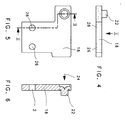
- Dashed line 16 is a steel insert plate 18 indicated in detail in FIGS. 4 to 6 is shown and described.
- the steel insert plate 18 is at a distance from the Outer edges of the bolt foot 12 and the bolt body 14, which means that this is completely from one Die casting material 20 is cast. However, this relates not on a guide pin 22 which, as shown in FIG clearly recognizable, the die casting material 20 penetrates and clearly surpassed this.
- the guide pin 22 is made of the level of the steel insert plate 18 by means of a Embossing process shaped in the direction of arrow 24, see above that it sticks out sideways.
- the Steel insert plate 18 and openings 26 and 28th molded in when casting the steel insert plate 18th Pick up die casting material 20.
- the guide pin 22 engages in one (not shown) as a control element trained connecting rod connecting slide, over which of the bolt latch 10 from the lock housing pushed out or retracted into it.
- the bolt body 14 is, as can be seen from Figure 1, in two lateral areas 30 and 32 and a central area 34 divided, the central region 34 one over the Has outer surface 36 protruding guide surface 38, which can be clearly seen from Figure 2.
- the respective Widths of the areas 30 to 34 are approximately the same size.
- the guide surface 38 tapers, starting from the free front edge 40 of the bolt body 14 in the direction of Bar foot 12, i.e. its width 42 decreases. in the Cross-section, the guide surface 38 is part-circular configured, which is clear from Figure 3.
- a lock with such a bolt 10 offers a much greater resistance to burglary since One of the bolt bolts 10 has a greater width than conventional bolts and also the steel insert plate 18 a deformation or destruction of the bolt bolt 10 prevented.
- the guide surface 38 ensures despite large width of the bolt bolt 10 a smooth Preliminary, since the contact surface of the bolt bolt 10, the is defined by the guide surface 38 in size is limited, and thereby the frictional forces are minimal being held.
- the above also allows Guide pin 22 an indirect introduction of the actuating forces on the steel insert plate 18 and thus an optimal one Distribution within the bolt bolt 10.
Landscapes
- Connection Of Plates (AREA)
- Insertion Pins And Rivets (AREA)
- Lock And Its Accessories (AREA)
- Pharmaceuticals Containing Other Organic And Inorganic Compounds (AREA)
- Hydrogenated Pyridines (AREA)
- Credit Cards Or The Like (AREA)
Abstract
Description
- Fig. 1
- eine Draufsicht auf den erfindungsgemäßen Bolzenriegel;
- Figur 2
- eine Seitenansicht des Bolzenriegels gemäß Figur 1 in Richtung des Pfeils II;
- Figur 3
- eine weitere Seitenansicht des Bolzenriegels in Richtung des Pfeils III gemäß Figur 2;
- Figur 4
- eine Seitenansicht der Stahleinlegeplatte;
- Figur 5
- eine Draufsicht auf die Stahleinlegeplatte in Richtung des Pfeils V gemäß Figur 4; und
- Figur 6
- einen Schnitt VI-VI durch die Stahleinlegeplatte gemäß Figur 5.
Claims (12)
- Schloss, insbesondere Hauptschloss oder Zusatzriegelschloss, mit einem Schlossgehäuse und einem Bolzenriegel (10) mit Riegelfuß (12) und Bolzenkörper (14), wobei der Riegelfuß (12) im Schlossgehäuse verschieblich geführt und der Bolzenkörper (14) aus dem Schlossgehäuse ausschiebbar ist, dadurch gekennzeichnet, dass der Bolzenriegel (10) eine Einlegeplatte (18), insbesondere aus Stahl, aufweist, die von einem Druckgussmaterial (20) umgossen ist.
- Schloss nach Anspruch 1, dadurch gekennzeichnet, dass die Stahleinlegeplatte (18) sich in den Riegelfuß (12) und den Bolzenkörper (14) erstreckt.
- Schloss nach einem der vorhergehenden Ansprüche, dadurch gekennzeichnet, dass die Stahleinlegeplatte (18) wenigstens einen Durchbruch (26 bzw. 28) aufweist, in welchem sich das Druckgussmaterial (20) verankert.
- Schloss nach einem der vorhergehenden Ansprüche, dadurch gekennzeichnet, dass das Druckgussmaterial (20) eine Zink-Kupfer-Legierung ist.
- Schloss nach einem der vorhergehenden Ansprüche, dadurch gekennzeichnet, dass die Stahleinlegeplatte (18) gehärtet ist.
- Schloss nach einem der vorhergehenden Ansprüche, dadurch gekennzeichnet, dass aus der Ebene der Stahleinlegeplatte (18) ein Führungszapfen (22) herausgeprägt ist.
- Schloss nach Anspruch 6, dadurch gekennzeichnet, dass der Führungszapfen (22) das die Stahleinlegeplatte (18) umschließende Druckgussmaterial (20) überragt.
- Schloss nach einem der vorhergehenden Ansprüche, dadurch gekennzeichnet, dass der Bolzenkörper (14) in Ausschubrichtung gesehen zwei seitliche und einen mittleren Bereich (30 und 32 sowie 34) aufweist, die im wesentlichen gleiche Breiten aufweisen.
- Schloss nach Anspruch 8, dadurch gekennzeichnet, dass der mittlere Bereich (34) eine über die Außenoberfläche (36) der seitlichen Bereiche (30 und 32) überstehende Führungsfläche (38) aufweist.
- Schloss nach Anspruch 9, dadurch gekennzeichnet, dass die Breite der Führungsfläche (38) von der freien Vorderkante (40) des Bolzenkörpers (14) in Richtung des Riegelfußes (12) abnimmt.
- Schloss nach Anspruch 9 oder 10, dadurch gekennzeichnet, dass die Führungsfläche (38) im Querschnitt teilkreisförmig ausgebildet ist.
- Schloss nach einem der Ansprüche 9 bis 11, dadurch gekennzeichnet, dass die Führungsfläche (38) in Längsrichtung gesehen keilförmig bzw. kegelförmig ist.
Applications Claiming Priority (2)
| Application Number | Priority Date | Filing Date | Title |
|---|---|---|---|
| DE20202861U | 2002-02-20 | ||
| DE20202861U DE20202861U1 (de) | 2002-02-20 | 2002-02-20 | Schloss |
Publications (2)
| Publication Number | Publication Date |
|---|---|
| EP1338737A1 true EP1338737A1 (de) | 2003-08-27 |
| EP1338737B1 EP1338737B1 (de) | 2004-07-21 |
Family
ID=7968195
Family Applications (1)
| Application Number | Title | Priority Date | Filing Date |
|---|---|---|---|
| EP03001268A Expired - Lifetime EP1338737B1 (de) | 2002-02-20 | 2003-01-22 | Schloss |
Country Status (3)
| Country | Link |
|---|---|
| EP (1) | EP1338737B1 (de) |
| AT (1) | ATE271643T1 (de) |
| DE (2) | DE20202861U1 (de) |
Cited By (2)
| Publication number | Priority date | Publication date | Assignee | Title |
|---|---|---|---|---|
| DE102006000120A1 (de) * | 2006-03-16 | 2007-09-20 | Aug. Winkhaus Gmbh & Co. Kg | Antriebseinrichtung |
| CN103109027A (zh) * | 2010-02-24 | 2013-05-15 | 开开特股份公司 | 具有低噪声的锁弓的机动车锁 |
Citations (3)
| Publication number | Priority date | Publication date | Assignee | Title |
|---|---|---|---|---|
| FR2435587A1 (fr) * | 1978-09-08 | 1980-04-04 | Novobat Sarl | Cremone a galets haut et bas, ou a tringles haut et bas, a pene et a condamnation a verrouillage avec ressort |
| DE9321445U1 (de) * | 1993-02-12 | 1998-02-26 | Karl Fliether Gmbh & Co, 42551 Velbert | Insbesondere an Wohnungsabschließtüren einzusetzendes Schloß, insbesondere treibstangenbetätigbares Schloß |
| GB2360242A (en) * | 2000-03-17 | 2001-09-19 | Patterson & Rothwell Ltd | Moulded plastics components and method |
Family Cites Families (4)
| Publication number | Priority date | Publication date | Assignee | Title |
|---|---|---|---|---|
| US3659885A (en) | 1970-08-31 | 1972-05-02 | Adams Rite Mfg | Maximum security lock bolt |
| AT336436B (de) | 1975-05-06 | 1977-05-10 | Grundmann Rohrbacher Schlosser | Riegelelement fur schlosser |
| DE7533733U (de) | 1975-10-23 | 1976-02-26 | Fa. Wilhelm Karrenberg, 5620 Velbert | Druckguss-schlossriegel |
| DE20020623U1 (de) | 2000-12-04 | 2001-02-22 | Burg-Wächter KG, 58540 Meinerzhagen | Riegel für eine Sicherheitstür |
-
2002
- 2002-02-20 DE DE20202861U patent/DE20202861U1/de not_active Expired - Lifetime
-
2003
- 2003-01-22 EP EP03001268A patent/EP1338737B1/de not_active Expired - Lifetime
- 2003-01-22 DE DE50300033T patent/DE50300033D1/de not_active Expired - Lifetime
- 2003-01-22 AT AT03001268T patent/ATE271643T1/de active
Patent Citations (3)
| Publication number | Priority date | Publication date | Assignee | Title |
|---|---|---|---|---|
| FR2435587A1 (fr) * | 1978-09-08 | 1980-04-04 | Novobat Sarl | Cremone a galets haut et bas, ou a tringles haut et bas, a pene et a condamnation a verrouillage avec ressort |
| DE9321445U1 (de) * | 1993-02-12 | 1998-02-26 | Karl Fliether Gmbh & Co, 42551 Velbert | Insbesondere an Wohnungsabschließtüren einzusetzendes Schloß, insbesondere treibstangenbetätigbares Schloß |
| GB2360242A (en) * | 2000-03-17 | 2001-09-19 | Patterson & Rothwell Ltd | Moulded plastics components and method |
Cited By (3)
| Publication number | Priority date | Publication date | Assignee | Title |
|---|---|---|---|---|
| DE102006000120A1 (de) * | 2006-03-16 | 2007-09-20 | Aug. Winkhaus Gmbh & Co. Kg | Antriebseinrichtung |
| CN103109027A (zh) * | 2010-02-24 | 2013-05-15 | 开开特股份公司 | 具有低噪声的锁弓的机动车锁 |
| CN103109027B (zh) * | 2010-02-24 | 2015-08-12 | 开开特股份公司 | 具有低噪声的锁弓的机动车锁 |
Also Published As
| Publication number | Publication date |
|---|---|
| DE20202861U1 (de) | 2002-05-23 |
| EP1338737B1 (de) | 2004-07-21 |
| ATE271643T1 (de) | 2004-08-15 |
| DE50300033D1 (de) | 2004-08-26 |
Similar Documents
| Publication | Publication Date | Title |
|---|---|---|
| AT11491U1 (de) | Verriegelungsvorrichtung | |
| EP2236384B1 (de) | Verschlusskomponente für Stellzungen-Verschlussvorrichtung, Stellzungen-Verschlussvorrichtung und Weiche mit Stellzungen-Verschlussvorrichtung | |
| EP0681079A1 (de) | Fenster- oder Türrahmen mit darauf befestigtem Schliessblech und darin eingreifendem Schliessbolzen | |
| EP1338737B1 (de) | Schloss | |
| EP0957219B1 (de) | Steckzylinderschloss, insbesondere zur Verwendung an Schutzvorrichtungen für Spiel- und Warenautomaten | |
| DE2128721A1 (de) | Verschlußvorrichtung fur Türen und Fenster | |
| EP0013555B1 (de) | Schlosseinheit | |
| DE29509503U1 (de) | Mehrfachverriegelungsanlage | |
| EP1493889B1 (de) | Schliessplatte | |
| DE8203945U1 (de) | Kantengetriebe fuer ein fenster, eine tuer od. dgl. | |
| DE8534096U1 (de) | Zylinderschloß mit einer Nachschließsicherung | |
| EP0172575B1 (de) | Verbindungsanordnung | |
| DE19848071A1 (de) | Anordnungsvorrichtung für einen Öldruck-Türschließer | |
| EP2481872A2 (de) | Verriegelungsanordnung für Fenster, Türen oder dergleichen mit einem Schwenkriegel | |
| EP0500125B1 (de) | Verschluss für Fenster oder Türen | |
| DE4311970A1 (de) | Sicherheitsbeschlag | |
| DE4403870A1 (de) | Sicherheitstür | |
| DE4025315C1 (de) | ||
| DE3509724A1 (de) | Schlossschutzbeschlag | |
| EP0971093A1 (de) | Rahmen mit Füllung | |
| DE3215452A1 (de) | Eckumlenkung fuer treibstangenbeschlaege von fenstern, tueren od. dgl. | |
| DE102010032145B4 (de) | Torverriegelungsvorrichtung sowie Überkopftor umfassend eine Torverriegelungsvorrichtung | |
| DE3725000C2 (de) | ||
| DE29921489U1 (de) | Am Blendrahmen eines Fensters oder einer Tür festlegbares Riegelstück | |
| DE8104046U1 (de) | Tuerverschluss mit zusaetzlicher verriegelung |
Legal Events
| Date | Code | Title | Description |
|---|---|---|---|
| PUAI | Public reference made under article 153(3) epc to a published international application that has entered the european phase |
Free format text: ORIGINAL CODE: 0009012 |
|
| AK | Designated contracting states |
Designated state(s): AT BE BG CH CY CZ DE DK EE ES FI FR GB GR HU IE IT LI LU MC NL PT SE SI SK TR |
|
| AX | Request for extension of the european patent |
Extension state: AL LT LV MK RO |
|
| 17P | Request for examination filed |
Effective date: 20030917 |
|
| GRAP | Despatch of communication of intention to grant a patent |
Free format text: ORIGINAL CODE: EPIDOSNIGR1 |
|
| RAP1 | Party data changed (applicant data changed or rights of an application transferred) |
Owner name: GRETSCH-UNITAS GMBHBAUBESCHLAEGE |
|
| GRAS | Grant fee paid |
Free format text: ORIGINAL CODE: EPIDOSNIGR3 |
|
| AKX | Designation fees paid |
Designated state(s): AT BE BG CH CY CZ DE DK EE ES FI FR GB GR HU IE IT LI LU MC NL PT SE SI SK TR |
|
| GRAA | (expected) grant |
Free format text: ORIGINAL CODE: 0009210 |
|
| AK | Designated contracting states |
Kind code of ref document: B1 Designated state(s): AT BE BG CH CY CZ DE DK EE ES FI FR GB GR HU IE IT LI LU MC NL PT SE SI SK TR |
|
| PG25 | Lapsed in a contracting state [announced via postgrant information from national office to epo] |
Ref country code: TR Free format text: LAPSE BECAUSE OF FAILURE TO SUBMIT A TRANSLATION OF THE DESCRIPTION OR TO PAY THE FEE WITHIN THE PRESCRIBED TIME-LIMIT Effective date: 20040721 Ref country code: SK Free format text: LAPSE BECAUSE OF FAILURE TO SUBMIT A TRANSLATION OF THE DESCRIPTION OR TO PAY THE FEE WITHIN THE PRESCRIBED TIME-LIMIT Effective date: 20040721 Ref country code: SI Free format text: LAPSE BECAUSE OF FAILURE TO SUBMIT A TRANSLATION OF THE DESCRIPTION OR TO PAY THE FEE WITHIN THE PRESCRIBED TIME-LIMIT Effective date: 20040721 Ref country code: IE Free format text: LAPSE BECAUSE OF FAILURE TO SUBMIT A TRANSLATION OF THE DESCRIPTION OR TO PAY THE FEE WITHIN THE PRESCRIBED TIME-LIMIT Effective date: 20040721 Ref country code: FI Free format text: LAPSE BECAUSE OF FAILURE TO SUBMIT A TRANSLATION OF THE DESCRIPTION OR TO PAY THE FEE WITHIN THE PRESCRIBED TIME-LIMIT Effective date: 20040721 Ref country code: ES Free format text: LAPSE BECAUSE OF FAILURE TO SUBMIT A TRANSLATION OF THE DESCRIPTION OR TO PAY THE FEE WITHIN THE PRESCRIBED TIME-LIMIT Effective date: 20040721 Ref country code: EE Free format text: LAPSE BECAUSE OF FAILURE TO SUBMIT A TRANSLATION OF THE DESCRIPTION OR TO PAY THE FEE WITHIN THE PRESCRIBED TIME-LIMIT Effective date: 20040721 Ref country code: CZ Free format text: LAPSE BECAUSE OF FAILURE TO SUBMIT A TRANSLATION OF THE DESCRIPTION OR TO PAY THE FEE WITHIN THE PRESCRIBED TIME-LIMIT Effective date: 20040721 Ref country code: BG Free format text: LAPSE BECAUSE OF FAILURE TO SUBMIT A TRANSLATION OF THE DESCRIPTION OR TO PAY THE FEE WITHIN THE PRESCRIBED TIME-LIMIT Effective date: 20040721 |
|
| REG | Reference to a national code |
Ref country code: GB Ref legal event code: FG4D Free format text: NOT ENGLISH |
|
| REG | Reference to a national code |
Ref country code: CH Ref legal event code: EP |
|
| GBT | Gb: translation of ep patent filed (gb section 77(6)(a)/1977) |
Effective date: 20040721 |
|
| REG | Reference to a national code |
Ref country code: CH Ref legal event code: NV Representative=s name: TROESCH SCHEIDEGGER WERNER AG |
|
| REG | Reference to a national code |
Ref country code: IE Ref legal event code: FG4D Free format text: GERMAN |
|
| REF | Corresponds to: |
Ref document number: 50300033 Country of ref document: DE Date of ref document: 20040826 Kind code of ref document: P |
|
| PG25 | Lapsed in a contracting state [announced via postgrant information from national office to epo] |
Ref country code: SE Free format text: LAPSE BECAUSE OF FAILURE TO SUBMIT A TRANSLATION OF THE DESCRIPTION OR TO PAY THE FEE WITHIN THE PRESCRIBED TIME-LIMIT Effective date: 20041021 Ref country code: GR Free format text: LAPSE BECAUSE OF FAILURE TO SUBMIT A TRANSLATION OF THE DESCRIPTION OR TO PAY THE FEE WITHIN THE PRESCRIBED TIME-LIMIT Effective date: 20041021 Ref country code: DK Free format text: LAPSE BECAUSE OF FAILURE TO SUBMIT A TRANSLATION OF THE DESCRIPTION OR TO PAY THE FEE WITHIN THE PRESCRIBED TIME-LIMIT Effective date: 20041021 |
|
| PG25 | Lapsed in a contracting state [announced via postgrant information from national office to epo] |
Ref country code: HU Free format text: LAPSE BECAUSE OF FAILURE TO SUBMIT A TRANSLATION OF THE DESCRIPTION OR TO PAY THE FEE WITHIN THE PRESCRIBED TIME-LIMIT Effective date: 20041022 |
|
| ET | Fr: translation filed | ||
| PG25 | Lapsed in a contracting state [announced via postgrant information from national office to epo] |
Ref country code: LU Free format text: LAPSE BECAUSE OF NON-PAYMENT OF DUE FEES Effective date: 20050122 Ref country code: CY Free format text: LAPSE BECAUSE OF FAILURE TO SUBMIT A TRANSLATION OF THE DESCRIPTION OR TO PAY THE FEE WITHIN THE PRESCRIBED TIME-LIMIT Effective date: 20050122 |
|
| PG25 | Lapsed in a contracting state [announced via postgrant information from national office to epo] |
Ref country code: MC Free format text: LAPSE BECAUSE OF NON-PAYMENT OF DUE FEES Effective date: 20050131 |
|
| REG | Reference to a national code |
Ref country code: IE Ref legal event code: FD4D |
|
| PLBE | No opposition filed within time limit |
Free format text: ORIGINAL CODE: 0009261 |
|
| STAA | Information on the status of an ep patent application or granted ep patent |
Free format text: STATUS: NO OPPOSITION FILED WITHIN TIME LIMIT |
|
| 26N | No opposition filed |
Effective date: 20050422 |
|
| PG25 | Lapsed in a contracting state [announced via postgrant information from national office to epo] |
Ref country code: PT Free format text: LAPSE BECAUSE OF NON-PAYMENT OF DUE FEES Effective date: 20041221 |
|
| REG | Reference to a national code |
Ref country code: FR Ref legal event code: PLFP Year of fee payment: 14 |
|
| REG | Reference to a national code |
Ref country code: FR Ref legal event code: PLFP Year of fee payment: 15 |
|
| REG | Reference to a national code |
Ref country code: FR Ref legal event code: PLFP Year of fee payment: 16 |
|
| PGFP | Annual fee paid to national office [announced via postgrant information from national office to epo] |
Ref country code: GB Payment date: 20200123 Year of fee payment: 18 Ref country code: NL Payment date: 20200121 Year of fee payment: 18 Ref country code: AT Payment date: 20200122 Year of fee payment: 18 Ref country code: DE Payment date: 20200121 Year of fee payment: 18 Ref country code: IT Payment date: 20200131 Year of fee payment: 18 |
|
| PGFP | Annual fee paid to national office [announced via postgrant information from national office to epo] |
Ref country code: BE Payment date: 20200121 Year of fee payment: 18 Ref country code: CH Payment date: 20200121 Year of fee payment: 18 |
|
| PGFP | Annual fee paid to national office [announced via postgrant information from national office to epo] |
Ref country code: FR Payment date: 20200121 Year of fee payment: 18 |
|
| REG | Reference to a national code |
Ref country code: DE Ref legal event code: R119 Ref document number: 50300033 Country of ref document: DE |
|
| REG | Reference to a national code |
Ref country code: CH Ref legal event code: PL |
|
| REG | Reference to a national code |
Ref country code: NL Ref legal event code: MM Effective date: 20210201 |
|
| REG | Reference to a national code |
Ref country code: AT Ref legal event code: MM01 Ref document number: 271643 Country of ref document: AT Kind code of ref document: T Effective date: 20210122 |
|
| GBPC | Gb: european patent ceased through non-payment of renewal fee |
Effective date: 20210122 |
|
| REG | Reference to a national code |
Ref country code: BE Ref legal event code: MM Effective date: 20210131 |
|
| PG25 | Lapsed in a contracting state [announced via postgrant information from national office to epo] |
Ref country code: FR Free format text: LAPSE BECAUSE OF NON-PAYMENT OF DUE FEES Effective date: 20210131 Ref country code: NL Free format text: LAPSE BECAUSE OF NON-PAYMENT OF DUE FEES Effective date: 20210201 Ref country code: AT Free format text: LAPSE BECAUSE OF NON-PAYMENT OF DUE FEES Effective date: 20210122 |
|
| PG25 | Lapsed in a contracting state [announced via postgrant information from national office to epo] |
Ref country code: GB Free format text: LAPSE BECAUSE OF NON-PAYMENT OF DUE FEES Effective date: 20210122 Ref country code: CH Free format text: LAPSE BECAUSE OF NON-PAYMENT OF DUE FEES Effective date: 20210131 Ref country code: DE Free format text: LAPSE BECAUSE OF NON-PAYMENT OF DUE FEES Effective date: 20210803 Ref country code: LI Free format text: LAPSE BECAUSE OF NON-PAYMENT OF DUE FEES Effective date: 20210131 |
|
| PG25 | Lapsed in a contracting state [announced via postgrant information from national office to epo] |
Ref country code: IT Free format text: LAPSE BECAUSE OF NON-PAYMENT OF DUE FEES Effective date: 20210122 |
|
| PG25 | Lapsed in a contracting state [announced via postgrant information from national office to epo] |
Ref country code: BE Free format text: LAPSE BECAUSE OF NON-PAYMENT OF DUE FEES Effective date: 20210131 |