EP1338458A1 - Vorrichtung zum Übertragen von Antriebskraft von einer Antriebswelle auf eine Zapfwelle - Google Patents
Vorrichtung zum Übertragen von Antriebskraft von einer Antriebswelle auf eine Zapfwelle Download PDFInfo
- Publication number
- EP1338458A1 EP1338458A1 EP03003906A EP03003906A EP1338458A1 EP 1338458 A1 EP1338458 A1 EP 1338458A1 EP 03003906 A EP03003906 A EP 03003906A EP 03003906 A EP03003906 A EP 03003906A EP 1338458 A1 EP1338458 A1 EP 1338458A1
- Authority
- EP
- European Patent Office
- Prior art keywords
- speed
- control unit
- drive
- shaft
- drive device
- Prior art date
- Legal status (The legal status is an assumption and is not a legal conclusion. Google has not performed a legal analysis and makes no representation as to the accuracy of the status listed.)
- Granted
Links
- 230000005540 biological transmission Effects 0.000 claims description 19
- 238000002485 combustion reaction Methods 0.000 claims description 13
- 238000006073 displacement reaction Methods 0.000 claims description 7
- 230000001419 dependent effect Effects 0.000 claims description 4
- 244000061456 Solanum tuberosum Species 0.000 description 3
- 235000002595 Solanum tuberosum Nutrition 0.000 description 3
- 238000011161 development Methods 0.000 description 2
- 230000018109 developmental process Effects 0.000 description 2
- 239000003337 fertilizer Substances 0.000 description 2
- 239000000446 fuel Substances 0.000 description 2
- 230000002706 hydrostatic effect Effects 0.000 description 2
- 235000012015 potatoes Nutrition 0.000 description 2
- 244000025254 Cannabis sativa Species 0.000 description 1
- 239000012530 fluid Substances 0.000 description 1
- 238000012986 modification Methods 0.000 description 1
- 230000004048 modification Effects 0.000 description 1
Images

Classifications
-
- B—PERFORMING OPERATIONS; TRANSPORTING
- B60—VEHICLES IN GENERAL
- B60K—ARRANGEMENT OR MOUNTING OF PROPULSION UNITS OR OF TRANSMISSIONS IN VEHICLES; ARRANGEMENT OR MOUNTING OF PLURAL DIVERSE PRIME-MOVERS IN VEHICLES; AUXILIARY DRIVES FOR VEHICLES; INSTRUMENTATION OR DASHBOARDS FOR VEHICLES; ARRANGEMENTS IN CONNECTION WITH COOLING, AIR INTAKE, GAS EXHAUST OR FUEL SUPPLY OF PROPULSION UNITS IN VEHICLES
- B60K17/00—Arrangement or mounting of transmissions in vehicles
- B60K17/28—Arrangement or mounting of transmissions in vehicles characterised by arrangement, location, or type of power take-off
-
- F—MECHANICAL ENGINEERING; LIGHTING; HEATING; WEAPONS; BLASTING
- F16—ENGINEERING ELEMENTS AND UNITS; GENERAL MEASURES FOR PRODUCING AND MAINTAINING EFFECTIVE FUNCTIONING OF MACHINES OR INSTALLATIONS; THERMAL INSULATION IN GENERAL
- F16H—GEARING
- F16H47/00—Combinations of mechanical gearing with fluid clutches or fluid gearing
- F16H47/02—Combinations of mechanical gearing with fluid clutches or fluid gearing the fluid gearing being of the volumetric type
- F16H47/04—Combinations of mechanical gearing with fluid clutches or fluid gearing the fluid gearing being of the volumetric type the mechanical gearing being of the type with members having orbital motion
Definitions
- the invention relates to a device for transmitting Driving force from one with an internal combustion engine driven drive shaft on a PTO.
- PTO Power Take Off
- the PTO from the electrical Motors or generators independent of the internal combustion engine be operated when the clutch provided there is disengaged is.
- the internal combustion engine has clutches and gears is directly connected to the PTO shifts at clutch engaged the speed of the PTO driving drive shafts with a change in the speed of the Combustion engine. Therefore, the PTO can not be independent from the engine speed at a constant speed rotate.
- PTO driven implements have a path-dependent metering device, for example Seed drills, planters, potato planters, Fertilizer application machines, fertilizer spreaders and Atomizer.
- a PTO speed which is proportional to the speed of travel. If now spin the tractor wheels, the Cruising speed. If the PTO speed is included remains unchanged, the proportionality of the PTO speed to travel speed, and speed the path-dependent metering device will be relative to Increase driving speed. When planting potatoes this cause the potatoes to be released onto the ground and planted irregularly.
- the object underlying the invention is seen in a device for transmitting driving force from a Drive shaft on a PTO of the type mentioned specify by which the aforementioned problems are overcome become.
- a device is to be specified and be trained regardless of speed changes the internal combustion engine a PTO operation with a Enables substantially constant speed.
- the Device to be able to operate with a PTO PTO speed to allow a predetermined Has ratio value to the speed of travel.
- the inventive device for transmitting Driving force from one of an internal combustion engine drivable drive shaft on a PTO comprises a Gearbox and one that can be operated with variable speed Drive device, wherein the transmission a first and a second input interface and an output interface has, the first input interface with the Drive shaft is connected, the output interface is connected to the PTO, the output interface has a speed that depends on the speeds depends on the first and the second input interface, and wherein the drive device with the second input interface connected is.
- the Drive device realized in that a control unit is provided with the drive device in Active connection is established.
- This control unit generates Control signals representing the speed of the drive device varies that the speed of the output interface despite Speed variations of the drive shaft are essentially constant is.
- PTO driven implements are operated, the one require constant input speed, for example a Internal combustion engine of a tractor is not constant specified speed must be operated.
- a speed sensor To record the speed of a drive shaft driving internal combustion engine is a speed sensor provided the speed of the first input interface measures and a speed signal from the control unit is available provides.
- the drive device could be one with the first Input interface drivingly connected hydraulic pump and one driven by the hydraulic pump and the second Input interface of the transmission connected hydraulic motor exhibit. So part of the power transmission would be with the help the drive device realized by hydraulic means.
- the transmission should preferably be designed such that those to be transmitted by the hydraulic drive device Driving forces are in an area in which the Drive device a high or at least cheap Has efficiency.
- the Hydraulic pump a variable displacement pump and the hydraulic motor one Have constant motor.
- the transmission has one Planet carrier, planet gears, a ring gear and a Sun gear on.
- the planet carrier is for rotation with connected to the output shaft, which are planetary gears rotatably arranged on the planet carrier and the ring gear is attached for rotation with the output interface.
- the Ring gear is in mesh with the planet gears Connection and the sun gear is with the Planetary gears in meshing connection and is drivingly connected to the drive device.
- a is Travel speed signal generating travel speed signal, an operator controlled and a ratio signal generating ratio control unit and a control unit intended.
- the control unit is with the drive device operatively connected.
- the control unit receives the travel speed signal and the ratio signal and generates control signals representing the speed of the drive device varies in such a way that a predeterminable ratio between a driving speed and the speed of the Output interface is maintained.
- PTO shaft can be realized at which the speed of the PTO proportional to the speed of a tractor is controlled.
- a constant PTO speed can be achieved in that the device according to the invention a predetermined Operator-controlled speed control unit generating speed signal, a a speed signal of the output interface generating speed sensor of the output interface and one Has control unit.
- the control unit is here with the Drive device operatively connected and receives the predetermined Speed signal and the speed signal of the output interface.
- the control unit generates control signals that the Speed of the drive device varies such that the Speed of the output interface at a given Speed is maintained.
- a Speed signal of the planet gear carrier generating speed sensor, one control unit and one with variable speed operable drive device provided.
- the control unit receives the speed signal and generates a dependent one Control signal.
- the drive device receives the control signal and is drivingly connected to the sun gear.
- the control unit and the drive device work in this way together that the PTO despite speed variations of the Drive shaft with an essentially unchanged speed rotates.
- this embodiment can also be used in advantageously PTO-driven implements be operated with a constant input speed require, for example, an internal combustion engine Not at a constant predetermined speed must be operated.
- the drive device comprises a drive unit, the one Hydraulic pump includes the first Input interface of the transmission is drivingly connected.
- the drive unit further comprises a hydraulic motor, with the second input interface of the transmission connected is.
- a variable speed can be operated and a drive motor having a drive shaft and a Drive wheel may be provided, the drive wheel for rotation is connected to the drive shaft of the drive motor and in engaging connection with the sun gear.
- a first for rotation with the Planet gear carrier connected drive wheel, a variable displacement pump, a operated with variable speed and by the Variable pump driven constant hydraulic motor and an in engaging connection with the sun gear and attached for rotation with the drive shaft of the motor second drive wheel may be provided.
- a PTO gearbox with a power split transmission unit an output connected to a PTO, one with a Drive shaft of a motor connected first input and one second connected to the output of a drive device Input, the drive device with a variable Ratio value or can be operated with a variable speed is.
- a control unit controls the speed of the drive device depending on the detected speed of the Motors to keep the PTO speed constant.
- the Power-split transmission unit preferably comprises one Planetary gear unit.
- the drive device comprises preferably a hydraulically operated variable displacement pump drives a constant hydraulic motor, which in turn Sun gear of the planetary gear unit drives. This Device transmits driving power from both the engine and also from the drive device to the PTO.
- PTO-driven devices such as grass / hay distributors
- This device increases the economy of fuel consumption and reduces that from the operator or from others in the vicinity Noise perceived by the environment because the device Engine speed can be reduced.
- the Maintain hydraulic flow from the variable displacement pump even then if the engine is below its normal Speed runs when the PTO drives Drive train also drives the hydraulic variable pump.
- the control unit can control the speed of the drive device also as a function of the detected driving speed, the detected output speed, a user-definable Speed signal value and / or a user-definable Ratio between speed and PTO speed control to one by one operator fixed PTO speed or one of a predetermined ratio value set by an operator between speed and PTO speed.
- the PTO speed can be controlled to optimize the performance of the implement to achieve without the variations of Tractor speed or engine speed affects too become.
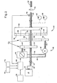
- Fig. 1 shows a PTO 10, the one power split transmission or a summing Planetary gear 12 has a main input shaft 14 which has a conventional speed reducing Gear unit 13 to an output shaft 15 of an engine 16 is coupled.
- the motor 16 is preferably in the form of a Internal combustion engine executed.
- the power split Gearbox or the summing planetary gear 12 is connected to one Output shaft 18 and via an input shaft 20 to a Variable speed drive device 22 coupled.
- the power split transmission or the totalizing Planetary gear 12 comprises a planet gear carrier 24, which on End of the main input shaft 14 is attached.
- Planetary gears 26 are rotatable on the planet gear carrier 24 arranged.
- a hollow sun shaft 28 is rotatable on the Input shaft 14 mounts and receives it.
- a first one smaller sun gear 30 is at one end of the sun shaft 28 rotatably fastened and has an engaging connection with the planetary gears 26.
- a larger second input sun gear 32 is at the other end of the sun wave 28 non-rotatably attached and is in an engaging connection with an input gear 34.
- a ring gear 36 surrounds and stands in engaging connection with the planetary gears 26.
- a Ring element 38 rotatably connects the ring gear 36 with the Output shaft 18.
- a larger drive wheel 40 is rotatably on the input shaft 14 between the motor 16 and the sun shaft 28 arranged.
- a smaller drive wheel 42 is shown in engaging connection with the drive wheel 40.
- the drive device 22 comprises a continuously variable Operable hydrostatic unit with a hydraulic variable pump 44 and one designed as a constant motor Hydraulic motor 46.
- the hydraulic variable pump 44 is from the drive wheel 42 driven via the drive shaft 48 and is with the hydraulic motor 46 via the hydraulic lines 50 and 52 connected.
- the hydraulic motor 46 drives the Input shaft 20 on.
- the drive device 22 can be in shape an integral hydrostatic unit or separate in Hydraulic pump and hydraulic motor to be executed, wherein in the latter case the hydraulic pump and the hydraulic motor over Hydraulic lines is connected.
- the output shaft 18 is preferably via a PTO clutch 54 connected to a PTO shaft 56, and can also be driving with a hydraulic pump 58 which Hydraulic fluid to a - not shown - Hydraulic system of an implement supplies, and one Hydraulic pump 60 for a - not shown - power steering of the Connected to the tractor.
- the speed-reducing gear unit 13 rotates the shaft 14 clockwise - seen from the back, i.e. of the right side of the figure - at a speed of 1000 Revolutions per minute if the engine is preferably with a Speed of 2200 revolutions per minute runs.
- the planet gears 26 each 39 teeth
- the sun gear 30 contains 24 teeth
- the Sun gear 32 contains 88 teeth
- the input gear 34 contains 22 teeth
- the ring gear 36 contains 102 teeth
- the Drive wheel 40 contains 60 teeth
- drive wheel 42 contains 15 teeth.
- a control unit 62 receives an engine speed signal from the speed shaft sensor 64 and generates a control signal that the hydraulic pump 44 is provided to thereby adjust their adjustment value.
- the control unit 62 is for Setting the adjustment value of the hydraulic pump 44 preferably formed such that the speed of the hydraulic motor 46 linear between minus 4000 revolutions per minute - if the Motor runs at nominal speed - and plus 2630 revolutions per Minute - when the engine rotates at 1505 revolutions runs per minute - varies.
- the speed of the hydraulic motor 46 runs through zero revolutions per minute when the Engine speed the speed range between 1793 and 1779 Revolutions per minute.
- the result remains Speed of the ring gear 36 and the output shaft 18 in Essentially at 1000 rpm, though for example, the engine speed of 2200 revolutions per Minute to a lower speed of 1505 revolutions per minute Minute varies.
- the hydraulic pumps 58 and 60 can also be operated at a constant speed, so that the to an implement or other hydraulic Components delivered hydraulic flow are maintained can, even if the engine with a lower running at normal speed.
- control unit 62 receives a travel speed signal from one Speed sensor 70 receives, for example in Form of a conventional cruising speed radar system can be executed.
- the control unit 62 could also be a Ratio signal from a ratio control unit 72 or a travel speed signal or a speed signal of a Speed control unit 74 received.
- the ratio control unit 72 could, for example, take the form of a operator-controlled and in the - not shown - Operator console of a vehicle arranged signal generator be executed.
- the control unit 62 also uses the letter sequence ECU denotes and is an abbreviation for the term electronic Control unit.
- the control unit or ECU 62 also receives from one Speed sensor 76 a speed signal of the output shaft.
- the ECU is preferably used to control the adjustment value Hydraulic pump 44 programmed so that the speed of the Output shaft 18 related to a predeterminable ratio value is maintained at the speed of travel, the Ratio value from a ratio value control unit 72 is definable.
- the control unit or the ECU 62 can Control of the adjustment value of the hydraulic pump 44 also in this way be programmed that the speed of the output shaft 18 at a constant speed generated by the speed control unit 74 is definable, and using one of one Speed sensor 76 provided feedback signal is maintained.
Landscapes
- Engineering & Computer Science (AREA)
- Chemical & Material Sciences (AREA)
- Combustion & Propulsion (AREA)
- Transportation (AREA)
- Mechanical Engineering (AREA)
- Structure Of Transmissions (AREA)
- Control Of Transmission Device (AREA)
- Arrangement And Driving Of Transmission Devices (AREA)
- Auxiliary Drives, Propulsion Controls, And Safety Devices (AREA)
Abstract
Description
- Fig. 1
- eine schematische Darstellung eines ersten erfindungsgemäßen Ausführungsbeispiels und
- Fig. 2
- eine schematische Darstellung eines zweiten erfindungsgemäßen Ausführungsbeispiels.
Claims (11)
- Vorrichtung zum Übertragen von Antriebskraft von einer von einem Verbrennungsmotor antreibbaren Antriebswelle (15) auf eine Zapfwelle (56), mit einem Getriebe (10) und einer mit variabler Drehzahl betreibbaren Antriebsvorrichtung (22), wobei das Getriebe (10) eine erste und eine zweite Eingangsschnittstelle (14, 20) und eine Ausgangsschnittstelle (18) aufweist, wobei die erste Eingangsschnittstelle (14) mit der Antriebswelle (15) verbunden ist, wobei die Ausgangsschnittstelle (18) mit der Zapfwelle (56) verbunden ist, wobei die Ausgangsschnittstelle (18) eine Drehzahl aufweist, die von den Drehzahlen der ersten und der zweiten Eingangsschnittstelle (14, 20) abhängt, und wobei die Antriebsvorrichtung (22) mit der zweiten Eingangsschnittstelle (20) verbunden ist.
- Vorrichtung nach Anspruch 1, dadurch gekennzeichnet, dass eine Steuereinheit (62) mit der Antriebsvorrichtung (22) in Wirkverbindung steht, dass die Steuereinheit (62) Steuersignale erzeugt, die die Drehzahl der Antriebsvorrichtung (22) derart variiert, dass die Drehzahl der Ausgangsschnittstelle (18) trotz Drehzahlvariationen der Antriebswelle (15) im Wesentlichen konstant ist.
- Vorrichtung nach Anspruch 1 oder 2, dadurch gekennzeichnet, dass ein Drehzahlsensor (64) vorgesehen ist, der die Drehzahl der ersten Eingangsschnittstelle (14) misst und ein Drehzahlsignal der Steuereinheit (20) zur Verfügung stellt.
- Vorrichtung nach einem der vorhergehenden Ansprüche, dadurch gekennzeichnet, dass die Antriebsvorrichtung (22) eine mit der ersten Eingangsschnittstelle (14) antreibend verbundene Hydraulikpumpe (44) und einen von der Hydraulikpumpe (44) angetriebenen und mit der zweiten Eingangsschnittstelle (20) des Getriebes (10) verbundenen Hydraulikmotor (46) aufweist.
- Vorrichtung nach Anspruch 4, dadurch gekennzeichnet, dass die Hydraulikpumpe (44) eine Verstellpumpe und der Hydraulikmotor (46) einen Konstantmotor aufweist.
- Vorrichtung nach einem der vorhergehenden Ansprüche, dadurch gekennzeichnet, dass das Getriebe (10) einen Planetenradträger (24), Planetenzahnräder (26), ein Hohlrad (36) und ein Sonnenzahnrad (30) aufweist, wobei der Planetenradträger (24) zur Drehung mit der Abtriebswelle (15) verbunden ist, wobei die Planetenzahnräder (26) drehbar auf dem Planetenradträger (24) angeordnet sind, wobei das Hohlrad (36) zur Drehung mit der Ausgangsschnittstelle (18) befestigt ist, wobei das Hohlrad (36) mit den Planetenzahnrädern (26) in eingreifender Verbindung steht und wobei das Sonnenzahnrad (30) mit den Planetenzahnrädern (26) in eingreifender Verbindung steht und antreibend mit der Antriebsvorrichtung (22) verbunden ist.
- Vorrichtung nach einem der vorhergehenden Ansprüche, dadurch gekennzeichnet, dass ein ein Fahrtgeschwindigkeitssignal erzeugender Fahrtgeschwindigkeitssensor (70), eine bedienergesteuerte und ein Verhältniswertsignal erzeugende Verhältniswert-Steuereinheit (72) und eine Steuereinheit (62) vorgesehen ist, wobei die Steuereinheit (62) mit der Antriebsvorrichtung (22) wirkverbunden ist und die Steuereinheit (62) das Fahrtgeschwindigkeitssignal und das Verhältniswertsignal empfängt, wobei die Steuereinheit (62) Steuersignale erzeugt, die die Drehzahl der Antriebsvorrichtung (22) derart variiert, dass ein vorgebbarer Verhältniswert zwischen einer Fahrtgeschwindigkeit und der Drehzahl der Ausgangsschnittstelle (18) aufrechterhalten wird.
- Vorrichtung nach einem der vorhergehenden Ansprüche, dadurch gekennzeichnet, dass eine ein vorgegebenes Drehzahlsignal erzeugende bedienergesteuerte Drehzahlsteuereinheit (74), ein ein Drehzahlsignal der Ausgangsschnittstelle (18) erzeugender Drehzahlsensor (76) der Ausgangsschnittstelle (18) und eine Steuereinheit (62) vorgesehen ist, wobei die Steuereinheit (62) mit der Antriebsvorrichtung (22) wirkverbunden ist, wobei die Steuereinheit (62) das vorgegebene Drehzahlsignal und das Drehzahlsignal der Ausgangsschnittstelle (18) empfängt, und wobei die Steuereinheit (62) Steuersignale erzeugt, die die Drehzahl der Antriebsvorrichtung (22) derart variiert, dass die Drehzahl der Ausgangsschnittstelle (18) bei einer vorgegebenen Drehzahl aufrechterhalten wird.
- Vorrichtung nach einem der Ansprüche 6 bis 8, dadurch gekennzeichnet, dass ein ein Drehzahlsignal des Planetenradträgers (24) erzeugender Drehzahlsensor, eine Steuereinheit (62) und eine mit variabler Drehzahl betreibbaren Antriebsvorrichtung (22) vorgesehen ist, wobei die Steuereinheit (62) das Drehzahlsignal empfängt und ein davon abhängiges Steuersignal erzeugt, wobei die Antriebsvorrichtung (22) das Steuersignal empfängt und antreibend mit dem Sonnenzahnrad (32) verbunden ist und wobei die Steuereinheit (62) und die Antriebsvorrichtung (22) derart zusammenarbeiten, dass die Zapfwelle (56) trotz Drehzahlvariationen der Antriebswelle (15) mit einer im Wesentlichen unveränderten Drehzahl dreht.
- Vorrichtung nach einem der Ansprüche 6 bis 9, dadurch gekennzeichnet, dass ein mit variabler Drehzahl betreibbarer und eine Antriebswelle (20) aufweisender Antriebsmotor (46) und ein Antriebsrad (34) vorgesehen ist, wobei das Antriebsrad (34) zur Drehung mit der Antriebswelle (20) des Antriebsmotors (46) verbunden ist und in eingreifender Verbindung mit dem Sonnenzahnrad (32) steht.
- Vorrichtung nach einem der Ansprüche 6 bis 10, dadurch gekennzeichnet, dass ein zur Drehung mit dem Planetenradträger (24) verbundenes erstes Antriebsrad (40), eine eine Eingangswelle aufweisende und von dem ersten Antriebsrad (40) angetriebene Verstellpumpe (44), ein mit variabler Drehzahl betreibbar und von der Verstellpumpe hydraulisch angetriebener Konstant-Hydraulikmotor (46), der eine mit variabler Drehzahl betreibbaren Motorantriebswelle aufweist, und ein in eingreifender Verbindung mit dem Sonnenzahnrad (32) stehendes und zur Drehung mit der Antriebswelle (20) des Motors (46) verbundenes zweites Antriebsrad (34) vorgesehen ist.
Applications Claiming Priority (2)
| Application Number | Priority Date | Filing Date | Title |
|---|---|---|---|
| US82390 | 1979-10-05 | ||
| US10/082,390 US6692395B2 (en) | 2002-02-25 | 2002-02-25 | Transmisson for power take-off |
Publications (2)
| Publication Number | Publication Date |
|---|---|
| EP1338458A1 true EP1338458A1 (de) | 2003-08-27 |
| EP1338458B1 EP1338458B1 (de) | 2006-10-25 |
Family
ID=27660360
Family Applications (1)
| Application Number | Title | Priority Date | Filing Date |
|---|---|---|---|
| EP03003906A Expired - Lifetime EP1338458B1 (de) | 2002-02-25 | 2003-02-21 | Vorrichtung zum Übertragen von Antriebskraft von einer Antriebswelle auf eine Zapfwelle |
Country Status (5)
| Country | Link |
|---|---|
| US (1) | US6692395B2 (de) |
| EP (1) | EP1338458B1 (de) |
| AU (1) | AU2003200618B2 (de) |
| BR (1) | BR0300217A (de) |
| DE (1) | DE50305454D1 (de) |
Cited By (10)
| Publication number | Priority date | Publication date | Assignee | Title |
|---|---|---|---|---|
| WO2005082664A1 (de) * | 2004-02-26 | 2005-09-09 | Zf Friedrichshafen Ag | Verfahren zum betrieb einer mit einem antriebsmotor gekoppelten wegzapfwelle |
| EP1466773A3 (de) * | 2003-04-08 | 2006-06-21 | Deere & Company | Antriebsvorrichtung zum Antreiben von Zusatzgeräten für ein Fahrzeug |
| CN102275495A (zh) * | 2010-06-07 | 2011-12-14 | 通用汽车环球科技运作有限责任公司 | 具有双驱主泵的电动变矩器 |
| DE102011077089A1 (de) | 2011-06-07 | 2012-12-13 | Zf Friedrichshafen Ag | Getriebevorrichtung mit einer Antriebsmaschine eines Fahrzeugantriebsstranges koppelbaren Getriebeeingangswelle und einer mit einem Abtrieb eines Fahrzeugantriebsstranges verbindbaren Getriebeausgangswelle |
| DE102012006189A1 (de) * | 2012-03-27 | 2013-10-02 | Bomag Gmbh | Antriebsvorrichtung in einer selbstfahrenden Baumaschine sowie Verfahren zum Einstellen eines Drehzahlverhältnisses bei einer derartigen Antriebsvorrichtung |
| DE102012211531A1 (de) * | 2012-07-03 | 2014-01-09 | Zf Friedrichshafen Ag | Getriebe mit zuschaltbarem Variator |
| DE102012211533A1 (de) * | 2012-07-03 | 2014-01-23 | Zf Friedrichshafen Ag | Gruppengetriebe |
| CN108374875A (zh) * | 2018-04-25 | 2018-08-07 | 同济大学 | 一种变频变排量机械液压无级变速传动系统 |
| CN114312298A (zh) * | 2022-01-29 | 2022-04-12 | 潍柴动力股份有限公司 | 一种单发洗扫车及其控制方法 |
| DE102021210719A1 (de) | 2021-09-27 | 2023-03-30 | Zf Friedrichshafen Ag | Zapfwellenantriebseinrichtung für ein landwirtschaftliches oder kommunales Nutzfahrzeug |
Families Citing this family (50)
| Publication number | Priority date | Publication date | Assignee | Title |
|---|---|---|---|---|
| US6984171B2 (en) * | 2002-07-19 | 2006-01-10 | Cnh America Llc | Hydro-mechanical threshing rotor control system for an agricultural combine |
| DE102004007837A1 (de) * | 2004-02-17 | 2005-09-01 | Claas Selbstfahrende Erntemaschinen Gmbh | Landwirtschaftliche Arbeitsmaschine |
| US7357203B2 (en) * | 2004-09-28 | 2008-04-15 | Oshkosh Truck Corporation | Self-contained axle module |
| US7448460B2 (en) | 2004-09-28 | 2008-11-11 | Oshkosh Corporation | Power takeoff for an electric vehicle |
| US8561735B2 (en) * | 2004-09-28 | 2013-10-22 | Oshkosh Corporation | Self-contained axle module |
| US7207916B2 (en) | 2005-01-05 | 2007-04-24 | Deere & Company | Transmission for power take-off |
| DE102005003035A1 (de) * | 2005-01-22 | 2006-09-07 | Pfalz, Rainer | Stufenloses Tandem-Automat-Getriebe |
| US7252623B2 (en) * | 2005-08-03 | 2007-08-07 | Deere & Company | Method of using a PTO clutch for auxiliary load measurement |
| US20100174456A1 (en) * | 2006-08-23 | 2010-07-08 | S.O.E. Technologies Inc. | Mechanical cvt drive train and control method for earth working vehicle |
| US20080103006A1 (en) * | 2006-10-30 | 2008-05-01 | Sauer-Danfoss Inc. | Hydromechanical transmission with input summer |
| US7597641B2 (en) * | 2006-12-26 | 2009-10-06 | Po-Lu Chen | Gearing unit for power transferring system |
| CA2575181A1 (en) * | 2007-01-24 | 2008-07-24 | Park Lake Welding & Manufacturing Ltd. | Auxiliary transmission for a motor vehicle |
| US8182395B2 (en) | 2007-02-21 | 2012-05-22 | Volvo Lastvagnar Ab | Method for adapting vehicle drivetrain control based on a measured PTO load |
| US9061680B2 (en) | 2007-07-12 | 2015-06-23 | Odyne Systems, Llc | Hybrid vehicle drive system and method for fuel reduction during idle |
| US9878616B2 (en) | 2007-07-12 | 2018-01-30 | Power Technology Holdings Llc | Hybrid vehicle drive system and method using split shaft power take off |
| US8978798B2 (en) * | 2007-10-12 | 2015-03-17 | Odyne Systems, Llc | Hybrid vehicle drive system and method and idle reduction system and method |
| US8818588B2 (en) * | 2007-07-12 | 2014-08-26 | Odyne Systems, Llc | Parallel hybrid drive system utilizing power take off connection as transfer for a secondary energy source |
| US20120207620A1 (en) | 2007-07-12 | 2012-08-16 | Odyne Systems, LLC. | Hybrid vehicle drive system and method and idle reduction system and method |
| US8408341B2 (en) | 2007-07-12 | 2013-04-02 | Odyne Systems, Llc | Hybrid vehicle drive system and method and idle reduction system and method |
| US7953535B2 (en) * | 2007-07-31 | 2011-05-31 | Caterpillar Inc. | Drive line torque perturbation for PTO mode shifting |
| US20090048053A1 (en) * | 2007-08-16 | 2009-02-19 | Ruppert Rex Leroy | Auxiliary transmission for a continously variable transmission with active speed control |
| US8365637B2 (en) * | 2007-10-23 | 2013-02-05 | Caterpillar Inc. | Drop box for powertrain |
| US8104288B2 (en) * | 2008-09-25 | 2012-01-31 | Honeywell International Inc. | Effusion cooling techniques for combustors in engine assemblies |
| US20120115668A1 (en) * | 2009-07-22 | 2012-05-10 | Renault Trucks | Drive arrangement for vehicle auxiliaries |
| BR112012022253A2 (pt) | 2010-03-03 | 2016-10-25 | Int Truck Intellectual Prop Co | controle de velocidade angular para máquinas motrizes de veículo híbrido |
| DE102010029866A1 (de) * | 2010-06-09 | 2011-12-15 | Zf Friedrichshafen Ag | Stufenloses Leistungsverzweigungsgetriebe mit einem Variator |
| EP2466168A1 (de) * | 2010-12-16 | 2012-06-20 | VDS Getriebe GmbH | Einrichtung zur Aufteilung der Antriebsleistung |
| ITTO20110136A1 (it) | 2011-02-17 | 2012-08-18 | Cnh Italia Spa | Sistema di trasmissione per pto in un veicolo agricolo o industriale, e relativo metodo operativo |
| EP2551140B1 (de) * | 2011-07-27 | 2018-04-25 | CLAAS Tractor S.A.S. | Landwirtschaftsfahrzeug und Betriebsverfahren |
| US12330657B2 (en) | 2011-12-02 | 2025-06-17 | Power Technology Holdings Llc | Hybrid vehicle drive system and method for fuel reduction during idle |
| JP6226202B2 (ja) | 2011-12-02 | 2017-11-08 | パワー テクノロジー ホールディングス,エルエルシー | ハイブリッド車における燃料最適化装置及び方法 |
| US11225240B2 (en) | 2011-12-02 | 2022-01-18 | Power Technology Holdings, Llc | Hybrid vehicle drive system and method for fuel reduction during idle |
| CA2836823C (en) * | 2012-08-13 | 2020-10-06 | Clark Equipment Company | Automatic shift of mechanical gearbox |
| GB201223544D0 (en) * | 2012-12-21 | 2013-02-13 | Agco Int Gmbh | Power take off drive system for a vehicle |
| CN106061784B (zh) | 2013-11-18 | 2019-07-19 | 电力科技控股有限责任公司 | 采用分轴式动力输出装置的混合动力车辆驱动系统和方法 |
| DE102015009809A1 (de) * | 2015-07-28 | 2017-02-02 | Grimme Landmaschinenfabrik Gmbh & Co. Kg | Landwirtschaftliche Arbeitsmaschine mit zumindest einem Anbaugerät |
| US10077828B2 (en) * | 2016-04-18 | 2018-09-18 | Caterpillar Inc. | Powertrain system for machine and method of operating same |
| EP3646694B1 (de) * | 2017-06-28 | 2023-10-11 | Kubota Corporation | Arbeitssteuerungssystem für eine arbeitsmaschine |
| US11628942B2 (en) | 2019-03-01 | 2023-04-18 | Pratt & Whitney Canada Corp. | Torque ripple control for an aircraft power train |
| US11732639B2 (en) | 2019-03-01 | 2023-08-22 | Pratt & Whitney Canada Corp. | Mechanical disconnects for parallel power lanes in hybrid electric propulsion systems |
| EP3931091B1 (de) | 2019-03-01 | 2025-10-29 | Pratt & Whitney Canada Corp. | Verteilte antriebskonfigurationen für flugzeug mit gemischten antriebssystemen |
| CA3132285A1 (en) | 2019-03-01 | 2020-09-10 | Pratt & Whitney Canada Corp. | Torque balancing for hybrid electric propulsion systems and aircraft utilizing hybrid electric propulsion systems |
| EP3941830B1 (de) | 2019-03-18 | 2024-11-06 | Pratt & Whitney Canada Corp. | Architekturen für hybrid-elektro-antrieb |
| WO2021092682A1 (en) * | 2019-11-14 | 2021-05-20 | Transmission Cvtcorp Inc. | Hybrid implement drive |
| US11572672B2 (en) * | 2020-02-21 | 2023-02-07 | Deere & Company | Method to decouple engine speed from hydraulic pump speed through an electric motor driven variator |
| US11486472B2 (en) | 2020-04-16 | 2022-11-01 | United Technologies Advanced Projects Inc. | Gear sytems with variable speed drive |
| US11607950B2 (en) | 2020-05-14 | 2023-03-21 | Cnh Industrial America Llc | Transmission system for a work vehicle |
| US11713237B2 (en) * | 2020-07-14 | 2023-08-01 | Paragon Tank Truck Equipment, Llc | Liquid discharge system including liquid product pump having vibration sensor |
| US20220169232A1 (en) * | 2020-12-02 | 2022-06-02 | Caterpillar Paving Products Inc. | Machine and drivetrain associated with machine |
| DE102020134114A1 (de) | 2020-12-18 | 2022-06-23 | Deere & Company | Getriebe und landwirtschaftliches oder industrielles Nutzfahrzeug |
Citations (8)
| Publication number | Priority date | Publication date | Assignee | Title |
|---|---|---|---|---|
| US4191270A (en) * | 1977-09-01 | 1980-03-04 | Steiger Tractor, Inc. | Control for tractor power takeoff shaft |
| SU1142315A1 (ru) * | 1983-01-21 | 1985-02-28 | Минский Ордена Ленина И Ордена Октябрьской Революции Тракторный Завод | Механизм привода вала отбора мощности транспортного средства |
| DE4024063A1 (de) * | 1990-07-28 | 1992-01-30 | Bayerische Motoren Werke Ag | Antriebsanordnung fuer ein nebenaggregat von brennkraftmaschinen in kraftfahrzeugen, insbesondere fuer eine pumpe |
| WO1994007056A1 (de) * | 1992-09-12 | 1994-03-31 | Bavaria-Tech Werner Schlattl | Variator sowie antriebsaggregat, insbesondere für fahrzeuge, mit einem solchen variator |
| DE19811691A1 (de) * | 1998-03-18 | 1999-09-23 | Bosch Gmbh Robert | Einrichtung zum Betreiben eines an einem landwirtschaftlichen Arbeitsfahrzeug angehängten Arbeitsgeräts |
| US6138069A (en) * | 1999-05-24 | 2000-10-24 | Textron Inc. | Utility vehicle with work-performing attachment |
| US6145455A (en) * | 1999-03-17 | 2000-11-14 | Case Corporation | Agricultural material metering system |
| EP1072817A2 (de) * | 1999-07-29 | 2001-01-31 | New Holland Belgium N.V. | Hydromechanisches Getriebe für eine landwirtschaftliche Erntemaschine |
Family Cites Families (13)
| Publication number | Priority date | Publication date | Assignee | Title |
|---|---|---|---|---|
| US4774855A (en) * | 1982-08-17 | 1988-10-04 | Vickers Shipbuilding And Engineering Limited | Apparatus for providing an electrical generator with a constant rotational speed from a variable speed input |
| JPS60196449A (ja) * | 1984-03-19 | 1985-10-04 | Ube Ind Ltd | 定速駆動装置 |
| USRE34023E (en) | 1984-03-30 | 1992-08-11 | Dana Corporation | Power takeoff speed control assembly |
| US4973295A (en) * | 1989-03-31 | 1990-11-27 | Gabrielle Reng-Yi Wu Lee | Stepless variable ratio transmission |
| US5211064A (en) | 1991-05-20 | 1993-05-18 | Sauer Inc. | Power take-off drive |
| US5562173A (en) | 1994-04-14 | 1996-10-08 | New Holland North America, Inc. | Power take-off electronic control with RPM interlock |
| DE19512637A1 (de) | 1995-04-05 | 1996-10-10 | Claas Ohg | Antriebseinheit, Verfahren zu deren Steuerung und Verwendung derselben |
| US5682315A (en) * | 1995-05-31 | 1997-10-28 | Caterpillar Inc. | Method and system for controlling a split torque transmission |
| US5669842A (en) | 1996-04-29 | 1997-09-23 | General Motors Corporation | Hybrid power transmission with power take-off apparatus |
| US6105353A (en) * | 1996-05-28 | 2000-08-22 | Claas Kgaa | Planetary transmission for baler |
| US5765650A (en) | 1996-12-03 | 1998-06-16 | Ag Designs, Incorporated | Hydraulic power coupling for agricultural equipment |
| US5988004A (en) | 1997-09-15 | 1999-11-23 | Mtd Products Inc | Internal power take-off shaft |
| DE19812500B4 (de) * | 1998-03-21 | 2006-05-11 | Deere & Company, Moline | Zuführvorrichtung |
-
2002
- 2002-02-25 US US10/082,390 patent/US6692395B2/en not_active Expired - Lifetime
-
2003
- 2003-02-20 BR BR0300217-9A patent/BR0300217A/pt not_active IP Right Cessation
- 2003-02-21 DE DE50305454T patent/DE50305454D1/de not_active Expired - Lifetime
- 2003-02-21 AU AU2003200618A patent/AU2003200618B2/en not_active Ceased
- 2003-02-21 EP EP03003906A patent/EP1338458B1/de not_active Expired - Lifetime
Patent Citations (8)
| Publication number | Priority date | Publication date | Assignee | Title |
|---|---|---|---|---|
| US4191270A (en) * | 1977-09-01 | 1980-03-04 | Steiger Tractor, Inc. | Control for tractor power takeoff shaft |
| SU1142315A1 (ru) * | 1983-01-21 | 1985-02-28 | Минский Ордена Ленина И Ордена Октябрьской Революции Тракторный Завод | Механизм привода вала отбора мощности транспортного средства |
| DE4024063A1 (de) * | 1990-07-28 | 1992-01-30 | Bayerische Motoren Werke Ag | Antriebsanordnung fuer ein nebenaggregat von brennkraftmaschinen in kraftfahrzeugen, insbesondere fuer eine pumpe |
| WO1994007056A1 (de) * | 1992-09-12 | 1994-03-31 | Bavaria-Tech Werner Schlattl | Variator sowie antriebsaggregat, insbesondere für fahrzeuge, mit einem solchen variator |
| DE19811691A1 (de) * | 1998-03-18 | 1999-09-23 | Bosch Gmbh Robert | Einrichtung zum Betreiben eines an einem landwirtschaftlichen Arbeitsfahrzeug angehängten Arbeitsgeräts |
| US6145455A (en) * | 1999-03-17 | 2000-11-14 | Case Corporation | Agricultural material metering system |
| US6138069A (en) * | 1999-05-24 | 2000-10-24 | Textron Inc. | Utility vehicle with work-performing attachment |
| EP1072817A2 (de) * | 1999-07-29 | 2001-01-31 | New Holland Belgium N.V. | Hydromechanisches Getriebe für eine landwirtschaftliche Erntemaschine |
Cited By (15)
| Publication number | Priority date | Publication date | Assignee | Title |
|---|---|---|---|---|
| EP1466773A3 (de) * | 2003-04-08 | 2006-06-21 | Deere & Company | Antriebsvorrichtung zum Antreiben von Zusatzgeräten für ein Fahrzeug |
| US8290667B2 (en) | 2004-02-26 | 2012-10-16 | Zf Friedrichshafen Ag | Method for the operation of a traveling power take-off shaft coupled to a driving motor |
| WO2005082664A1 (de) * | 2004-02-26 | 2005-09-09 | Zf Friedrichshafen Ag | Verfahren zum betrieb einer mit einem antriebsmotor gekoppelten wegzapfwelle |
| CN102275495B (zh) * | 2010-06-07 | 2014-03-26 | 通用汽车环球科技运作有限责任公司 | 具有双驱主泵的电动变矩器 |
| CN102275495A (zh) * | 2010-06-07 | 2011-12-14 | 通用汽车环球科技运作有限责任公司 | 具有双驱主泵的电动变矩器 |
| DE102011077089A1 (de) | 2011-06-07 | 2012-12-13 | Zf Friedrichshafen Ag | Getriebevorrichtung mit einer Antriebsmaschine eines Fahrzeugantriebsstranges koppelbaren Getriebeeingangswelle und einer mit einem Abtrieb eines Fahrzeugantriebsstranges verbindbaren Getriebeausgangswelle |
| DE102012006189A1 (de) * | 2012-03-27 | 2013-10-02 | Bomag Gmbh | Antriebsvorrichtung in einer selbstfahrenden Baumaschine sowie Verfahren zum Einstellen eines Drehzahlverhältnisses bei einer derartigen Antriebsvorrichtung |
| DE102012211531A1 (de) * | 2012-07-03 | 2014-01-09 | Zf Friedrichshafen Ag | Getriebe mit zuschaltbarem Variator |
| DE102012211533A1 (de) * | 2012-07-03 | 2014-01-23 | Zf Friedrichshafen Ag | Gruppengetriebe |
| US8936528B2 (en) | 2012-07-03 | 2015-01-20 | Zf Friedrichshafen Ag | Transmission with disengageable variator |
| CN108374875A (zh) * | 2018-04-25 | 2018-08-07 | 同济大学 | 一种变频变排量机械液压无级变速传动系统 |
| DE102021210719A1 (de) | 2021-09-27 | 2023-03-30 | Zf Friedrichshafen Ag | Zapfwellenantriebseinrichtung für ein landwirtschaftliches oder kommunales Nutzfahrzeug |
| WO2023046846A1 (de) | 2021-09-27 | 2023-03-30 | Zf Friedrichshafen Ag | Zapfwellenantriebseinrichtung für ein landwirtschaftliches oder kommunales nutzfahrzeug |
| CN114312298A (zh) * | 2022-01-29 | 2022-04-12 | 潍柴动力股份有限公司 | 一种单发洗扫车及其控制方法 |
| CN114312298B (zh) * | 2022-01-29 | 2023-12-15 | 潍柴动力股份有限公司 | 一种单发洗扫车及其控制方法 |
Also Published As
| Publication number | Publication date |
|---|---|
| AU2003200618A1 (en) | 2003-09-11 |
| US6692395B2 (en) | 2004-02-17 |
| EP1338458B1 (de) | 2006-10-25 |
| AU2003200618B2 (en) | 2008-06-19 |
| BR0300217A (pt) | 2004-08-10 |
| US20030162619A1 (en) | 2003-08-28 |
| DE50305454D1 (de) | 2006-12-07 |
Similar Documents
| Publication | Publication Date | Title |
|---|---|---|
| EP1338458B1 (de) | Vorrichtung zum Übertragen von Antriebskraft von einer Antriebswelle auf eine Zapfwelle | |
| EP1679218B1 (de) | Vorrichtung zum Übertragen eines Drehmoments | |
| EP2193293B1 (de) | Hydrostatisch-mechanisches leistungsverzweigungsgetriebe | |
| DE69921550T2 (de) | Elektromechanisches compound-split-fahrzeuggetriebene mit zwei betriebsarten | |
| EP2193287B1 (de) | Leistungsverzweigungsgetriebe | |
| DE602004009697T2 (de) | Hydromechanisches getriebe für landwirtschaftstraktoren | |
| DE102017210095A1 (de) | Variator für einen Arbeitsfahrzeug-Antriebsstrang | |
| EP3754226A1 (de) | Lastschaltgetriebe | |
| DE2645907A1 (de) | Zahnraederwechselgetriebe in gruppenbauweise | |
| DE2335629C3 (de) | Hydrostatisch-mechanischer Antrieb fur land- und bauwirtschaftlich genutzte Fahrzeuge | |
| DE3710560A1 (de) | Getriebe fuer einen schlepper | |
| DE102006047577B4 (de) | Antriebsanordnung für ein Aggregat eines landwirtschaftlichen Geräts oder einer landwirtschaftlichen Maschine | |
| DE19924304A1 (de) | Antriebssystem mit variabler Drehzahl für eine Rotoranordnung eines Korndreschmechanismuses | |
| EP2248698B1 (de) | Antriebsstrang eines Nutzfahrzeugs umfassend ein Stufenlos-Getriebe | |
| US6139458A (en) | Hydrostatic/direct drive transmission system and associated method | |
| EP2248699A1 (de) | Antriebsstrang eines Kraftfahrzeuges umfassend ein Stufenlos-Getriebe | |
| EP0693392A1 (de) | Landwirtschaftlicher Traktor mit elektromechanischem Getriebe | |
| EP1718490A1 (de) | Verfahren zum betrieb einer mit einem antriebsmotor gekoppelten wegzapfwelle | |
| DE3621166A1 (de) | Hydromechanisches fahrzeuggetriebe | |
| EP0045022A2 (de) | Hydromechanisches Getriebe | |
| DE3125122A1 (de) | Getriebe fuer ein fahrzeug, insbesondere schleppergetriebe | |
| DE10332216B4 (de) | Hydrostatisch-mechanisches Leistungsverzweigungsgetriebe | |
| DE69919958T2 (de) | Traktor mit Schmierungssystem | |
| DE10026670B4 (de) | Verteilergetriebe für einen Allradantrieb | |
| DE102008040444A1 (de) | Leistungsverzweigungsgetriebe |
Legal Events
| Date | Code | Title | Description |
|---|---|---|---|
| PUAI | Public reference made under article 153(3) epc to a published international application that has entered the european phase |
Free format text: ORIGINAL CODE: 0009012 |
|
| AK | Designated contracting states |
Designated state(s): AT BE BG CH CY CZ DE DK EE ES FI FR GB GR HU IE IT LI LU MC NL PT SE SI SK TR |
|
| AX | Request for extension of the european patent |
Extension state: AL LT LV MK RO |
|
| 17P | Request for examination filed |
Effective date: 20040227 |
|
| AKX | Designation fees paid |
Designated state(s): DE FR GB IT |
|
| 17Q | First examination report despatched |
Effective date: 20040512 |
|
| GRAP | Despatch of communication of intention to grant a patent |
Free format text: ORIGINAL CODE: EPIDOSNIGR1 |
|
| GRAS | Grant fee paid |
Free format text: ORIGINAL CODE: EPIDOSNIGR3 |
|
| GRAA | (expected) grant |
Free format text: ORIGINAL CODE: 0009210 |
|
| AK | Designated contracting states |
Kind code of ref document: B1 Designated state(s): DE FR GB IT |
|
| REG | Reference to a national code |
Ref country code: GB Ref legal event code: FG4D Free format text: NOT ENGLISH |
|
| REF | Corresponds to: |
Ref document number: 50305454 Country of ref document: DE Date of ref document: 20061207 Kind code of ref document: P |
|
| GBT | Gb: translation of ep patent filed (gb section 77(6)(a)/1977) |
Effective date: 20061220 |
|
| ET | Fr: translation filed | ||
| PLBE | No opposition filed within time limit |
Free format text: ORIGINAL CODE: 0009261 |
|
| STAA | Information on the status of an ep patent application or granted ep patent |
Free format text: STATUS: NO OPPOSITION FILED WITHIN TIME LIMIT |
|
| 26N | No opposition filed |
Effective date: 20070726 |
|
| PGFP | Annual fee paid to national office [announced via postgrant information from national office to epo] |
Ref country code: GB Payment date: 20090227 Year of fee payment: 7 |
|
| PGFP | Annual fee paid to national office [announced via postgrant information from national office to epo] |
Ref country code: IT Payment date: 20090224 Year of fee payment: 7 |
|
| PGFP | Annual fee paid to national office [announced via postgrant information from national office to epo] |
Ref country code: FR Payment date: 20090217 Year of fee payment: 7 |
|
| GBPC | Gb: european patent ceased through non-payment of renewal fee |
Effective date: 20100221 |
|
| REG | Reference to a national code |
Ref country code: FR Ref legal event code: ST Effective date: 20101029 |
|
| PG25 | Lapsed in a contracting state [announced via postgrant information from national office to epo] |
Ref country code: FR Free format text: LAPSE BECAUSE OF NON-PAYMENT OF DUE FEES Effective date: 20100301 |
|
| PG25 | Lapsed in a contracting state [announced via postgrant information from national office to epo] |
Ref country code: IT Free format text: LAPSE BECAUSE OF NON-PAYMENT OF DUE FEES Effective date: 20100221 Ref country code: GB Free format text: LAPSE BECAUSE OF NON-PAYMENT OF DUE FEES Effective date: 20100221 |
|
| PGFP | Annual fee paid to national office [announced via postgrant information from national office to epo] |
Ref country code: DE Payment date: 20200121 Year of fee payment: 18 |
|
| REG | Reference to a national code |
Ref country code: DE Ref legal event code: R119 Ref document number: 50305454 Country of ref document: DE |
|
| PG25 | Lapsed in a contracting state [announced via postgrant information from national office to epo] |
Ref country code: DE Free format text: LAPSE BECAUSE OF NON-PAYMENT OF DUE FEES Effective date: 20210901 |