EP1337005A1 - Sockelabschluss für Stecksockelsystem - Google Patents
Sockelabschluss für Stecksockelsystem Download PDFInfo
- Publication number
- EP1337005A1 EP1337005A1 EP02405111A EP02405111A EP1337005A1 EP 1337005 A1 EP1337005 A1 EP 1337005A1 EP 02405111 A EP02405111 A EP 02405111A EP 02405111 A EP02405111 A EP 02405111A EP 1337005 A1 EP1337005 A1 EP 1337005A1
- Authority
- EP
- European Patent Office
- Prior art keywords
- base
- socket
- plug
- termination
- positioning
- Prior art date
- Legal status (The legal status is an assumption and is not a legal conclusion. Google has not performed a legal analysis and makes no representation as to the accuracy of the status listed.)
- Granted
Links
- 239000004020 conductor Substances 0.000 description 4
- 241001417534 Lutjanidae Species 0.000 description 2
- 230000007935 neutral effect Effects 0.000 description 2
- 125000006850 spacer group Chemical group 0.000 description 2
- 230000015572 biosynthetic process Effects 0.000 description 1
- 239000000969 carrier Substances 0.000 description 1
- 230000001419 dependent effect Effects 0.000 description 1
- 239000000428 dust Substances 0.000 description 1
- 238000010292 electrical insulation Methods 0.000 description 1
- 238000005755 formation reaction Methods 0.000 description 1
- 238000001746 injection moulding Methods 0.000 description 1
- 230000002427 irreversible effect Effects 0.000 description 1
- 238000000034 method Methods 0.000 description 1
- 230000003287 optical effect Effects 0.000 description 1
- 230000001681 protective effect Effects 0.000 description 1
Images
Classifications
-
- H—ELECTRICITY
- H01—ELECTRIC ELEMENTS
- H01R—ELECTRICALLY-CONDUCTIVE CONNECTIONS; STRUCTURAL ASSOCIATIONS OF A PLURALITY OF MUTUALLY-INSULATED ELECTRICAL CONNECTING ELEMENTS; COUPLING DEVICES; CURRENT COLLECTORS
- H01R9/00—Structural associations of a plurality of mutually-insulated electrical connecting elements, e.g. terminal strips or terminal blocks; Terminals or binding posts mounted upon a base or in a case; Bases therefor
- H01R9/22—Bases, e.g. strip, block, panel
- H01R9/24—Terminal blocks
- H01R9/26—Clip-on terminal blocks for side-by-side rail- or strip-mounting
- H01R9/2616—End clamping members
-
- H—ELECTRICITY
- H02—GENERATION; CONVERSION OR DISTRIBUTION OF ELECTRIC POWER
- H02B—BOARDS, SUBSTATIONS OR SWITCHING ARRANGEMENTS FOR THE SUPPLY OR DISTRIBUTION OF ELECTRIC POWER
- H02B1/00—Frameworks, boards, panels, desks, casings; Details of substations or switching arrangements
- H02B1/015—Boards, panels, desks; Parts thereof or accessories therefor
- H02B1/04—Mounting thereon of switches or of other devices in general, the switch or device having, or being without, casing
- H02B1/056—Mounting on plugboards
Definitions
- the present invention relates to the field of low voltage distribution boards Socket type. It relates to a plinth termination for plug-in plinth systems according to the Preamble of claim 1 and a low-voltage socket system according to the preamble of claim 9.
- Socket type low voltage distributors include a busbar Receiving plug base system, on which modular plug-in parts, such as switching and Protection devices with various functions, infeed blocks or Terminals to be plugged on. Enable such low voltage distributors a time and cost saving planning and execution of a distributor and stand out due to rapid producibility, simple feeding and easy interchangeability the plug-in parts.
- plug-in base system known under the name "smissline-S" Surge arrester for modular power distribution up to 160 A nominal current is for example from the company's 20112 / B "Surge protection in the system" of the company ABB CMC Components, Zurich / Switzerland.
- Any number of plug-in base modules units or units with standardized width can be used for the desired socket width be put together and offer space for more or less plug-in parts.
- the Modules designed in such a way that they are attached to each other when they are joined together can.
- the resulting socket is placed on a wall of a building or switch box fixed, standardized mounting rail mounted. Then busbars with a length corresponding to the resulting socket width in the Plug socket introduced.
- the plug-in base system comprises at least one main base for receiving six Busbars for the three phases and a neutral conductor as well as two auxiliary rails. Often there is an additional base for holding two more busbars for external earth and neutral conductors are provided.
- additional base In the German Offenlegungsschrift DE 199 57 277.1 is such an additional base, also designed as a plug-in base discloses which can be snapped onto the main base by means of snap hooks.
- the object of the present invention is to provide a base termination for plug-in base systems specify which is easy to assemble and to integrate additional functions suitable is. This task is completed by a plinth with the characteristics of Claim 1 solved.
- the essence of the invention is positioning elements in the case of base closures or base end pieces provide the location of the former relative to the socket system clearly determine whether or not the system has an additional base has or not. Since there are no duplicate positioning elements, first, the plinth end is made simpler, and second, the Assembly no confusion problems. Due to the unique position of the When the base is assembled, it is also worth integrating additional functions, in addition to protection against accidental contact, in the end. The necessary ones additional configurations which interact with the plug-in base system, This is because they must also be provided only once and not twice.
- Positioning elements equipped, which interact with the plug base In a first embodiment of the base closure according to the invention, this is included Positioning elements equipped, which interact with the plug base.
- the Base termination can have further or alternative positioning elements, which one Allow attachment to a mounting rail that also carries the plug base.
- a base closure according to the invention can perceive a crawl and airway extension between neighboring Busbars. This is achieved by means of webs which extend into the Conductor rails come to rest and prevent them from reaching the height of the side of the plug base to slip.
- the base end piece can also be used Have carriers on which a distributor cover can be mounted.
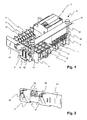
- a socket system with a main socket 1 is shown of which, in the chosen perspective, the right half exemplifies a single protective device 2 is plugged in, while the left half of the slots is not occupied.
- the base 1 In grooves the base 1, a plurality of busbars 11, 12, 13 are inserted over the entire width of the base 1 lead and which with terminals, not shown, the Protection device 2 form a contact.
- On the back, facing away from the viewer the main socket 1 is an additional socket 3 with two others Additional busbars 31.32 shown. This additional base 3 is on the main socket 1 snapped.
- the main socket 1 is fastened on a mounting rail 10 and preferably snapped on, but can also be screwed directly onto a base.
- the base 1, 3 is a conventional injection molding technique according to the invention manufactured plug base termination 4.4 'attached. Since the two ends of the Main connector base 1 are designed differently to connect two The left-hand side 4 and the right-hand side are possible to enable one or more base modules 4 'Termination generally not exactly mirror-symmetrical.
- the degrees 4,4 ' cover the ends of the busbars 11, 12, 31, 32 over the entire depth of the base system and thus form a protection against accidental contact.
- a plinth end 4 relative to the plinth 1 is clearly defined, i.e. the termination 4 cannot in two or more, in a direction perpendicular to the busbars 11, 12 different, positions can be attached.
- a in the illustration according to Fig.1 Viewers facing away, additional final part 41 of the conclusion 4 can be removed.
- said protruding additional end part 41 is canceled, which by a corresponding design of a predetermined breaking point as Perforation or notch is facilitated.
- the predetermined breaking point can also be done by previous Cracks should be prepared accordingly with a pointed object.
- FIG. 1 shows a simple embodiment of such a cover 5, wherein only a part facing the viewer is shown, which is in the form of a rectangular Plastic part 51 over the entire width of the socket over a front shoulder of the Plug parts 2 runs.
- spacers 52 which are arranged between the carrier 43 and the plastic part 51.
- this has two conical pins 44 on the outside as the first Positioning.
- These pins 44 can be in a commercially available, shown in Fig., Terminal 6 are inserted, which in turn clamp on the mounting rail 10th screwed and / or snapped.
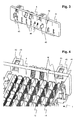
- FIG. 3 shows an inner side facing the plug-in base 1 in the terminology shown on the left-hand end 4.
- Snappers 45 are clearly recognizable as further positioning elements. This catch 45 engage in the assembly of the Completion 4 in corresponding grooves or slots of the base 1 and can by a screwdriver. Between the two snaps 45 points the conclusion 4 on six ribs or webs 46. These come in the assembled state to lie exactly in the extension of the conductor rails. That through the predetermined breaking point 42 separated additional end part 41 of the end 4 has two further ribs 47.
- FIG. 4 finally shows a section of a main socket 1 with a next to it is a plug-in base termination 4 ', of which in turn the inside, if not covered by the base 1, is visible.
- the arrangement is clearly visible the webs 46 in the extension of the busbars 11, 12. Through these webs 46 Creepage distance between two adjacent busbars 11, 12 over their shortest Distance is increased and the risk of voltage flashover reduced.
- hexagon nuts 53 are shown in a corresponding cavity of the carrier. The latter serve as a counterpart for the spacer bolts 52 of the cover 5, which again screwed into the nuts 53. Said nuts will be 53 suitably into the cavity from the side facing away from the plug-in base introduced and held there by a tab 48 recognizable in FIG.
Landscapes
- Engineering & Computer Science (AREA)
- Power Engineering (AREA)
- Connector Housings Or Holding Contact Members (AREA)
Abstract
Description
- Fig. 1
- ein Stecksockelsystem mit zwei Sockelabschlüssen,
- Fig.2
- eine Aussenseite eines linken Sockelabschluss,
- Fig.3
- eine Innenseite eines rechten Sockelabschluss, und
- Fig.4
- ein Detail eines Stecksockelsystems ohne Steckteil.
- 1
- Hauptstecksockel
- 10
- Befestigungsschiene
- 11,12
- Stromschienen
- 2
- Schutzgerät
- 3
- Zusatzstecksockel
- 31,32
- Zusatzstromschienen
- 4,4'
- Sockelabschluss
- 41
- Zusatzsockelabschluss
- 42
- Sollbruchstelle
- 43
- Träger
- 44
- Zapfen
- 45
- Schnapper
- 46,47
- Rippen
- 48
- Lasche
- 5
- Verteilerabdeckung
- 51
- Kunststoffteil
- 52
- Distanzbolzen
- 53
- Mutter
- 6
- Klemme
Claims (10)
- Sockelabschluss (4,4') für Niederspannungs-Stecksockelsysteme mit einem Hauptstecksockel (1) und wahlweise einem Zusatzstecksockel (2), wobei der Sockelabschluss (4,4') Positionierelemente (44,45) aufweist zur Positionierung des Sockelabschluss (4,4') neben einer seitlichen Stirnfläche des Hauptstecksockels (1), dadurch gekennzeichnet, dass sämtliche Positionierelemente (44,45) dieselbe Position des Sockelabschluss (4,4') relativ zum Hauptstecksockel (1) festlegen.
- Sockelabschluss (4,4') nach Anspruch 1, dadurch gekennzeichnet, dass ein erstes Positionierelement (45) zur Befestigung des Sockelabschluss (4,4') am Hauptstecksockel (1) ausgebildet ist.
- Sockelabschluss (4,4') nach Anspruch 2, dadurch gekennzeichnet, dass das erste Positionierelement einen Schnappmechanismus (45) aufweist.
- Sockelabschluss (4,4') nach Anspruch 1, dadurch gekennzeichnet, dass ein zweites Positionierelement (44) zur Befestigung des Sockelabschluss (4,4') an einer Klemme (6), welche auf eine Befestigungsschiene (10) montierbar ist, ausgebildet ist.
- Sockelabschluss (4,4') nach Anspruch 4, dadurch gekennzeichnet, dass das zweite Positionierelement konische Zapfen (44) aufweist, welche in die Klemme (6) einführbar sind.
- Sockelabschluss (4,4') nach einem der Ansprüche 1 bis 5, dadurch gekennzeichnet, dass er Rippen oder Stege (46) zur Kriechwegverlängerung zwischen zwei benachbarten, in den Hauptstecksockel (1) eingebrachten Stromschienen (11,12; 12,13), aufweist.
- Sockelabschluss (4,4') nach einem der Ansprüche 1 bis 5, dadurch gekennzeichnet, dass er Träger (43) zur Aufnahme einer Verteilerabdeckung (5) aufweist.
- Sockelabschluss (4,4') nach einem der Ansprüche 1 bis 5, dadurch gekennzeichnet, dass er einen entfernbaren Zusatzsockelabschluss (41) umfasst.
- Niederspannungs-Stecksockelsystem, umfassend einen Hauptstecksockel (1) mit einer seitlichen Stirnfläche, in den Hauptstecksockel (1) eingelegte Stromschienen (11,12,13) und einen Sockelabschluss (4,4') mit Positionierelementen (44,45) zur Positionierung des Sockelabschluss (4,4') neben der seitlichen Stirnfläche des Hauptstecksockels (1), dadurch gekennzeichnet, dass die Position des Sockelabschluss (4,4') relativ zum Hauptstecksockel (1) durch sämtliche Positionierelemente (44,45) eindeutig festgelegt ist.
- Stecksockelsystem nach Anspruch 9, dadurch gekennzeichnet, dass es einen Zusatzstecksockel (3) und darin eingelegte Zusatzstromschienen (31,32) umfasst.
Priority Applications (1)
| Application Number | Priority Date | Filing Date | Title |
|---|---|---|---|
| EP02405111.2A EP1337005B1 (de) | 2002-02-14 | 2002-02-14 | Sockelabschluss für Stecksockelsystem |
Applications Claiming Priority (1)
| Application Number | Priority Date | Filing Date | Title |
|---|---|---|---|
| EP02405111.2A EP1337005B1 (de) | 2002-02-14 | 2002-02-14 | Sockelabschluss für Stecksockelsystem |
Publications (2)
| Publication Number | Publication Date |
|---|---|
| EP1337005A1 true EP1337005A1 (de) | 2003-08-20 |
| EP1337005B1 EP1337005B1 (de) | 2014-10-29 |
Family
ID=27619203
Family Applications (1)
| Application Number | Title | Priority Date | Filing Date |
|---|---|---|---|
| EP02405111.2A Expired - Lifetime EP1337005B1 (de) | 2002-02-14 | 2002-02-14 | Sockelabschluss für Stecksockelsystem |
Country Status (1)
| Country | Link |
|---|---|
| EP (1) | EP1337005B1 (de) |
Cited By (3)
| Publication number | Priority date | Publication date | Assignee | Title |
|---|---|---|---|---|
| DE202017104591U1 (de) | 2017-08-01 | 2018-11-06 | Wago Verwaltungsgesellschaft Mbh | Sockeleinheit für Reiheneinbaugeräteanordnung |
| US10700464B2 (en) | 2016-05-17 | 2020-06-30 | Woehner Gmbh & Co., Kg Elektrotechnische Systeme | Device for a busbar system |
| US11217970B2 (en) | 2017-05-08 | 2022-01-04 | Abb Schweiz Ag | Multiple fed busbar system |
Citations (2)
| Publication number | Priority date | Publication date | Assignee | Title |
|---|---|---|---|---|
| EP0837528A1 (de) * | 1996-10-15 | 1998-04-22 | Legrand | Anschlussleiste |
| DE19957277A1 (de) | 1999-11-29 | 2001-05-31 | Abb Cmc Carl Maier Ag Schaffha | Klemmanordnung für einen Niederspannungsverteiler |
Family Cites Families (2)
| Publication number | Priority date | Publication date | Assignee | Title |
|---|---|---|---|---|
| DE7025172U (de) * | 1970-07-04 | 1971-08-26 | Phoenix Elek Zitaetsgesellscha | Elektrotechnische klemmvorrichtung. |
| DE9203172U1 (de) * | 1992-03-10 | 1992-04-23 | Weidmueller Interface Gmbh & Co., 4930 Detmold, De |
-
2002
- 2002-02-14 EP EP02405111.2A patent/EP1337005B1/de not_active Expired - Lifetime
Patent Citations (2)
| Publication number | Priority date | Publication date | Assignee | Title |
|---|---|---|---|---|
| EP0837528A1 (de) * | 1996-10-15 | 1998-04-22 | Legrand | Anschlussleiste |
| DE19957277A1 (de) | 1999-11-29 | 2001-05-31 | Abb Cmc Carl Maier Ag Schaffha | Klemmanordnung für einen Niederspannungsverteiler |
Cited By (6)
| Publication number | Priority date | Publication date | Assignee | Title |
|---|---|---|---|---|
| US10700464B2 (en) | 2016-05-17 | 2020-06-30 | Woehner Gmbh & Co., Kg Elektrotechnische Systeme | Device for a busbar system |
| US10923850B2 (en) | 2016-05-17 | 2021-02-16 | Woehner Gmbh & Co., Kg Elektrotechnische Systeme | Device for securing an object on a rail |
| US11217970B2 (en) | 2017-05-08 | 2022-01-04 | Abb Schweiz Ag | Multiple fed busbar system |
| DE202017104591U1 (de) | 2017-08-01 | 2018-11-06 | Wago Verwaltungsgesellschaft Mbh | Sockeleinheit für Reiheneinbaugeräteanordnung |
| WO2019025139A1 (de) | 2017-08-01 | 2019-02-07 | Wago Verwaltungsgesellschaft Mbh | Sockeleinheit für reiheneinbaugeräteanordnung |
| DE102018005683A1 (de) | 2017-08-01 | 2019-02-07 | WAGO Verwaltungsgesellschaft mit beschränkter Haftung | Sockeleinheit für Reiheneinbaugeräteanordnung |
Also Published As
| Publication number | Publication date |
|---|---|
| EP1337005B1 (de) | 2014-10-29 |
Similar Documents
| Publication | Publication Date | Title |
|---|---|---|
| EP3066903B1 (de) | Komponentenaufbausystem | |
| DE20318511U1 (de) | Rahmengestell mit einer Elektrifiziereinrichtung | |
| DE102012213281A1 (de) | Feldbusbaukastensystem, Trägermodul und Feldbusmodul | |
| WO2011054743A2 (de) | Montageanordnung für elektrische geräte | |
| EP0668637B1 (de) | Steckdosenleiste | |
| EP0379662A2 (de) | Steckdosenbox | |
| EP0053252B1 (de) | Adapter für elektrische Installationsgeräte | |
| EP0252512B1 (de) | Mehrfach-Steckverbindungseinheit | |
| EP1337005B1 (de) | Sockelabschluss für Stecksockelsystem | |
| DE19628957A1 (de) | Anschlußvorrichtung für elektrische Installationsgeräte | |
| EP1472766B1 (de) | Anschluss- oder verteilvorrichtung für elektrische installationsgeräte | |
| DE3641153C2 (de) | ||
| DE3412452A1 (de) | Schutzstecker fuer verteilerleisten | |
| EP1638123B1 (de) | Leitungsschutzschalter mit verschiebbarem Steckkontakt | |
| DE19755690C2 (de) | Schaltschrank | |
| DE202004011908U1 (de) | Überspannungsableiter-Anordnung mit einer als Bestandteil eines Gehäuses ausführbaren Trägerplatte | |
| EP0127849A2 (de) | Relais | |
| DE3024843C2 (de) | Flachsteckerklemme | |
| WO2005025011A1 (de) | Stromschienen-system | |
| EP0975079A2 (de) | Installationsverteiler | |
| WO1999006242A1 (de) | Potentialverteilungssystem zur potentialverteilung an verbraucher sowie geeigneter verbinder | |
| EP1403990B1 (de) | Elektrische Installationseinrichtung | |
| EP0496977B1 (de) | Verteiler für elektrische Anlagen | |
| EP0339492B1 (de) | Anordnung zum wahlweisen Verbinden elektrischer Leitungen | |
| EP0303857B1 (de) | Trägerelement |
Legal Events
| Date | Code | Title | Description |
|---|---|---|---|
| PUAI | Public reference made under article 153(3) epc to a published international application that has entered the european phase |
Free format text: ORIGINAL CODE: 0009012 |
|
| AK | Designated contracting states |
Designated state(s): AT BE CH CY DE DK ES FI FR GB GR IE IT LI LU MC NL PT SE TR |
|
| AX | Request for extension of the european patent |
Extension state: AL LT LV MK RO SI |
|
| 17P | Request for examination filed |
Effective date: 20040205 |
|
| AKX | Designation fees paid |
Designated state(s): AT BE CH CY DE DK ES FI FR GB GR IE IT LI LU MC NL PT SE TR |
|
| 17Q | First examination report despatched |
Effective date: 20110921 |
|
| GRAP | Despatch of communication of intention to grant a patent |
Free format text: ORIGINAL CODE: EPIDOSNIGR1 |
|
| INTG | Intention to grant announced |
Effective date: 20140707 |
|
| GRAS | Grant fee paid |
Free format text: ORIGINAL CODE: EPIDOSNIGR3 |
|
| GRAA | (expected) grant |
Free format text: ORIGINAL CODE: 0009210 |
|
| AK | Designated contracting states |
Kind code of ref document: B1 Designated state(s): AT BE CH CY DE DK ES FI FR GB GR IE IT LI LU MC NL PT SE TR |
|
| REG | Reference to a national code |
Ref country code: GB Ref legal event code: FG4D Free format text: NOT ENGLISH |
|
| REG | Reference to a national code |
Ref country code: CH Ref legal event code: EP |
|
| REG | Reference to a national code |
Ref country code: AT Ref legal event code: REF Ref document number: 693957 Country of ref document: AT Kind code of ref document: T Effective date: 20141115 |
|
| REG | Reference to a national code |
Ref country code: IE Ref legal event code: FG4D Free format text: LANGUAGE OF EP DOCUMENT: GERMAN |
|
| REG | Reference to a national code |
Ref country code: DE Ref legal event code: R096 Ref document number: 50215990 Country of ref document: DE Effective date: 20141211 |
|
| REG | Reference to a national code |
Ref country code: NL Ref legal event code: VDEP Effective date: 20141029 |
|
| PG25 | Lapsed in a contracting state [announced via postgrant information from national office to epo] |
Ref country code: NL Free format text: LAPSE BECAUSE OF FAILURE TO SUBMIT A TRANSLATION OF THE DESCRIPTION OR TO PAY THE FEE WITHIN THE PRESCRIBED TIME-LIMIT Effective date: 20141029 Ref country code: FI Free format text: LAPSE BECAUSE OF FAILURE TO SUBMIT A TRANSLATION OF THE DESCRIPTION OR TO PAY THE FEE WITHIN THE PRESCRIBED TIME-LIMIT Effective date: 20141029 Ref country code: PT Free format text: LAPSE BECAUSE OF FAILURE TO SUBMIT A TRANSLATION OF THE DESCRIPTION OR TO PAY THE FEE WITHIN THE PRESCRIBED TIME-LIMIT Effective date: 20150302 Ref country code: ES Free format text: LAPSE BECAUSE OF FAILURE TO SUBMIT A TRANSLATION OF THE DESCRIPTION OR TO PAY THE FEE WITHIN THE PRESCRIBED TIME-LIMIT Effective date: 20141029 |
|
| PGFP | Annual fee paid to national office [announced via postgrant information from national office to epo] |
Ref country code: DE Payment date: 20150219 Year of fee payment: 14 |
|
| PG25 | Lapsed in a contracting state [announced via postgrant information from national office to epo] |
Ref country code: GR Free format text: LAPSE BECAUSE OF FAILURE TO SUBMIT A TRANSLATION OF THE DESCRIPTION OR TO PAY THE FEE WITHIN THE PRESCRIBED TIME-LIMIT Effective date: 20150130 Ref country code: CY Free format text: LAPSE BECAUSE OF FAILURE TO SUBMIT A TRANSLATION OF THE DESCRIPTION OR TO PAY THE FEE WITHIN THE PRESCRIBED TIME-LIMIT Effective date: 20141029 Ref country code: SE Free format text: LAPSE BECAUSE OF FAILURE TO SUBMIT A TRANSLATION OF THE DESCRIPTION OR TO PAY THE FEE WITHIN THE PRESCRIBED TIME-LIMIT Effective date: 20141029 |
|
| REG | Reference to a national code |
Ref country code: DE Ref legal event code: R097 Ref document number: 50215990 Country of ref document: DE |
|
| PG25 | Lapsed in a contracting state [announced via postgrant information from national office to epo] |
Ref country code: DK Free format text: LAPSE BECAUSE OF FAILURE TO SUBMIT A TRANSLATION OF THE DESCRIPTION OR TO PAY THE FEE WITHIN THE PRESCRIBED TIME-LIMIT Effective date: 20141029 |
|
| PG25 | Lapsed in a contracting state [announced via postgrant information from national office to epo] |
Ref country code: IT Free format text: LAPSE BECAUSE OF FAILURE TO SUBMIT A TRANSLATION OF THE DESCRIPTION OR TO PAY THE FEE WITHIN THE PRESCRIBED TIME-LIMIT Effective date: 20141029 |
|
| PLBE | No opposition filed within time limit |
Free format text: ORIGINAL CODE: 0009261 |
|
| STAA | Information on the status of an ep patent application or granted ep patent |
Free format text: STATUS: NO OPPOSITION FILED WITHIN TIME LIMIT |
|
| PG25 | Lapsed in a contracting state [announced via postgrant information from national office to epo] |
Ref country code: LU Free format text: LAPSE BECAUSE OF FAILURE TO SUBMIT A TRANSLATION OF THE DESCRIPTION OR TO PAY THE FEE WITHIN THE PRESCRIBED TIME-LIMIT Effective date: 20150214 |
|
| REG | Reference to a national code |
Ref country code: CH Ref legal event code: PL |
|
| 26N | No opposition filed |
Effective date: 20150730 |
|
| GBPC | Gb: european patent ceased through non-payment of renewal fee |
Effective date: 20150214 |
|
| PG25 | Lapsed in a contracting state [announced via postgrant information from national office to epo] |
Ref country code: CH Free format text: LAPSE BECAUSE OF NON-PAYMENT OF DUE FEES Effective date: 20150228 Ref country code: LI Free format text: LAPSE BECAUSE OF NON-PAYMENT OF DUE FEES Effective date: 20150228 Ref country code: MC Free format text: LAPSE BECAUSE OF FAILURE TO SUBMIT A TRANSLATION OF THE DESCRIPTION OR TO PAY THE FEE WITHIN THE PRESCRIBED TIME-LIMIT Effective date: 20141029 |
|
| REG | Reference to a national code |
Ref country code: IE Ref legal event code: MM4A |
|
| REG | Reference to a national code |
Ref country code: FR Ref legal event code: ST Effective date: 20151030 |
|
| PG25 | Lapsed in a contracting state [announced via postgrant information from national office to epo] |
Ref country code: GB Free format text: LAPSE BECAUSE OF NON-PAYMENT OF DUE FEES Effective date: 20150214 Ref country code: IE Free format text: LAPSE BECAUSE OF NON-PAYMENT OF DUE FEES Effective date: 20150214 |
|
| PG25 | Lapsed in a contracting state [announced via postgrant information from national office to epo] |
Ref country code: FR Free format text: LAPSE BECAUSE OF NON-PAYMENT OF DUE FEES Effective date: 20150302 |
|
| REG | Reference to a national code |
Ref country code: AT Ref legal event code: MM01 Ref document number: 693957 Country of ref document: AT Kind code of ref document: T Effective date: 20150214 |
|
| PG25 | Lapsed in a contracting state [announced via postgrant information from national office to epo] |
Ref country code: AT Free format text: LAPSE BECAUSE OF NON-PAYMENT OF DUE FEES Effective date: 20150214 |
|
| REG | Reference to a national code |
Ref country code: DE Ref legal event code: R119 Ref document number: 50215990 Country of ref document: DE |
|
| PG25 | Lapsed in a contracting state [announced via postgrant information from national office to epo] |
Ref country code: DE Free format text: LAPSE BECAUSE OF NON-PAYMENT OF DUE FEES Effective date: 20160901 |
|
| PG25 | Lapsed in a contracting state [announced via postgrant information from national office to epo] |
Ref country code: BE Free format text: LAPSE BECAUSE OF NON-PAYMENT OF DUE FEES Effective date: 20150228 |
|
| PG25 | Lapsed in a contracting state [announced via postgrant information from national office to epo] |
Ref country code: TR Free format text: LAPSE BECAUSE OF FAILURE TO SUBMIT A TRANSLATION OF THE DESCRIPTION OR TO PAY THE FEE WITHIN THE PRESCRIBED TIME-LIMIT Effective date: 20141029 |