EP1336034B1 - Vorrichtung und verfahren zur nachbehandlung von verbrennungskraftmaschinenabgasen - Google Patents
Vorrichtung und verfahren zur nachbehandlung von verbrennungskraftmaschinenabgasen Download PDFInfo
- Publication number
- EP1336034B1 EP1336034B1 EP01996674A EP01996674A EP1336034B1 EP 1336034 B1 EP1336034 B1 EP 1336034B1 EP 01996674 A EP01996674 A EP 01996674A EP 01996674 A EP01996674 A EP 01996674A EP 1336034 B1 EP1336034 B1 EP 1336034B1
- Authority
- EP
- European Patent Office
- Prior art keywords
- filled
- exhaust
- region
- hollow spheres
- exhaust gas
- Prior art date
- Legal status (The legal status is an assumption and is not a legal conclusion. Google has not performed a legal analysis and makes no representation as to the accuracy of the status listed.)
- Expired - Lifetime
Links
- 239000007789 gas Substances 0.000 title claims abstract description 66
- 238000002485 combustion reaction Methods 0.000 title claims abstract description 26
- 238000000034 method Methods 0.000 title claims abstract description 9
- 229910052751 metal Inorganic materials 0.000 claims abstract description 47
- 239000002184 metal Substances 0.000 claims abstract description 47
- 239000002245 particle Substances 0.000 claims abstract description 26
- 238000005054 agglomeration Methods 0.000 claims abstract description 4
- 230000002776 aggregation Effects 0.000 claims abstract description 4
- 230000003197 catalytic effect Effects 0.000 claims description 17
- 239000000463 material Substances 0.000 claims description 7
- 238000001914 filtration Methods 0.000 claims description 6
- PXHVJJICTQNCMI-UHFFFAOYSA-N Nickel Chemical compound [Ni] PXHVJJICTQNCMI-UHFFFAOYSA-N 0.000 claims description 4
- 238000009826 distribution Methods 0.000 claims description 4
- 229910045601 alloy Inorganic materials 0.000 claims description 3
- 239000000956 alloy Substances 0.000 claims description 3
- 229910000838 Al alloy Inorganic materials 0.000 claims description 2
- 229910000951 Aluminide Inorganic materials 0.000 claims description 2
- -1 iron-chromium-aluminium Chemical compound 0.000 claims description 2
- 229910052759 nickel Inorganic materials 0.000 claims description 2
- 230000007423 decrease Effects 0.000 claims 2
- 229910000990 Ni alloy Inorganic materials 0.000 claims 1
- BIJOYKCOMBZXAE-UHFFFAOYSA-N chromium iron nickel Chemical compound [Cr].[Fe].[Ni] BIJOYKCOMBZXAE-UHFFFAOYSA-N 0.000 claims 1
- 239000000835 fiber Substances 0.000 abstract description 28
- 238000000926 separation method Methods 0.000 abstract description 7
- 230000002411 adverse Effects 0.000 abstract description 3
- 230000000694 effects Effects 0.000 abstract description 3
- 238000010276 construction Methods 0.000 abstract description 2
- 239000011324 bead Substances 0.000 abstract 4
- 239000011148 porous material Substances 0.000 description 7
- 239000003054 catalyst Substances 0.000 description 6
- 230000008929 regeneration Effects 0.000 description 5
- 238000011069 regeneration method Methods 0.000 description 5
- 239000004071 soot Substances 0.000 description 5
- 239000011149 active material Substances 0.000 description 3
- 239000011248 coating agent Substances 0.000 description 3
- 238000000576 coating method Methods 0.000 description 3
- 230000002349 favourable effect Effects 0.000 description 3
- KDLHZDBZIXYQEI-UHFFFAOYSA-N Palladium Chemical compound [Pd] KDLHZDBZIXYQEI-UHFFFAOYSA-N 0.000 description 2
- 229910000831 Steel Inorganic materials 0.000 description 2
- 229910010293 ceramic material Inorganic materials 0.000 description 2
- VNNRSPGTAMTISX-UHFFFAOYSA-N chromium nickel Chemical compound [Cr].[Ni] VNNRSPGTAMTISX-UHFFFAOYSA-N 0.000 description 2
- 230000008021 deposition Effects 0.000 description 2
- 239000003344 environmental pollutant Substances 0.000 description 2
- 238000011049 filling Methods 0.000 description 2
- 150000002739 metals Chemical class 0.000 description 2
- 238000012856 packing Methods 0.000 description 2
- BASFCYQUMIYNBI-UHFFFAOYSA-N platinum Chemical compound [Pt] BASFCYQUMIYNBI-UHFFFAOYSA-N 0.000 description 2
- 231100000719 pollutant Toxicity 0.000 description 2
- 230000000717 retained effect Effects 0.000 description 2
- 238000005245 sintering Methods 0.000 description 2
- 239000010959 steel Substances 0.000 description 2
- 229910018487 Ni—Cr Inorganic materials 0.000 description 1
- PNEYBMLMFCGWSK-UHFFFAOYSA-N aluminium oxide Inorganic materials [O-2].[O-2].[O-2].[Al+3].[Al+3] PNEYBMLMFCGWSK-UHFFFAOYSA-N 0.000 description 1
- 238000011001 backwashing Methods 0.000 description 1
- 239000000969 carrier Substances 0.000 description 1
- 239000000919 ceramic Substances 0.000 description 1
- 238000005260 corrosion Methods 0.000 description 1
- 230000007797 corrosion Effects 0.000 description 1
- 238000011161 development Methods 0.000 description 1
- 230000018109 developmental process Effects 0.000 description 1
- 238000005485 electric heating Methods 0.000 description 1
- 230000017525 heat dissipation Effects 0.000 description 1
- 229930195733 hydrocarbon Natural products 0.000 description 1
- 150000002430 hydrocarbons Chemical class 0.000 description 1
- 238000011068 loading method Methods 0.000 description 1
- 238000004519 manufacturing process Methods 0.000 description 1
- 238000012986 modification Methods 0.000 description 1
- 230000004048 modification Effects 0.000 description 1
- 238000013021 overheating Methods 0.000 description 1
- 229910052763 palladium Inorganic materials 0.000 description 1
- 229910052697 platinum Inorganic materials 0.000 description 1
- 229910052703 rhodium Inorganic materials 0.000 description 1
- 239000010948 rhodium Substances 0.000 description 1
- MHOVAHRLVXNVSD-UHFFFAOYSA-N rhodium atom Chemical compound [Rh] MHOVAHRLVXNVSD-UHFFFAOYSA-N 0.000 description 1
- 238000007669 thermal treatment Methods 0.000 description 1
- 238000011144 upstream manufacturing Methods 0.000 description 1
Images

Classifications
-
- F—MECHANICAL ENGINEERING; LIGHTING; HEATING; WEAPONS; BLASTING
- F01—MACHINES OR ENGINES IN GENERAL; ENGINE PLANTS IN GENERAL; STEAM ENGINES
- F01N—GAS-FLOW SILENCERS OR EXHAUST APPARATUS FOR MACHINES OR ENGINES IN GENERAL; GAS-FLOW SILENCERS OR EXHAUST APPARATUS FOR INTERNAL COMBUSTION ENGINES
- F01N3/00—Exhaust or silencing apparatus having means for purifying, rendering innocuous, or otherwise treating exhaust
- F01N3/02—Exhaust or silencing apparatus having means for purifying, rendering innocuous, or otherwise treating exhaust for cooling, or for removing solid constituents of, exhaust
- F01N3/021—Exhaust or silencing apparatus having means for purifying, rendering innocuous, or otherwise treating exhaust for cooling, or for removing solid constituents of, exhaust by means of filters
- F01N3/033—Exhaust or silencing apparatus having means for purifying, rendering innocuous, or otherwise treating exhaust for cooling, or for removing solid constituents of, exhaust by means of filters in combination with other devices
- F01N3/035—Exhaust or silencing apparatus having means for purifying, rendering innocuous, or otherwise treating exhaust for cooling, or for removing solid constituents of, exhaust by means of filters in combination with other devices with catalytic reactors, e.g. catalysed diesel particulate filters
-
- B—PERFORMING OPERATIONS; TRANSPORTING
- B01—PHYSICAL OR CHEMICAL PROCESSES OR APPARATUS IN GENERAL
- B01J—CHEMICAL OR PHYSICAL PROCESSES, e.g. CATALYSIS OR COLLOID CHEMISTRY; THEIR RELEVANT APPARATUS
- B01J35/00—Catalysts, in general, characterised by their form or physical properties
- B01J35/19—Catalysts containing parts with different compositions
-
- B—PERFORMING OPERATIONS; TRANSPORTING
- B01—PHYSICAL OR CHEMICAL PROCESSES OR APPARATUS IN GENERAL
- B01J—CHEMICAL OR PHYSICAL PROCESSES, e.g. CATALYSIS OR COLLOID CHEMISTRY; THEIR RELEVANT APPARATUS
- B01J35/00—Catalysts, in general, characterised by their form or physical properties
- B01J35/50—Catalysts, in general, characterised by their form or physical properties characterised by their shape or configuration
- B01J35/51—Spheres
-
- B—PERFORMING OPERATIONS; TRANSPORTING
- B01—PHYSICAL OR CHEMICAL PROCESSES OR APPARATUS IN GENERAL
- B01J—CHEMICAL OR PHYSICAL PROCESSES, e.g. CATALYSIS OR COLLOID CHEMISTRY; THEIR RELEVANT APPARATUS
- B01J35/00—Catalysts, in general, characterised by their form or physical properties
- B01J35/50—Catalysts, in general, characterised by their form or physical properties characterised by their shape or configuration
- B01J35/58—Fabrics or filaments
-
- F—MECHANICAL ENGINEERING; LIGHTING; HEATING; WEAPONS; BLASTING
- F01—MACHINES OR ENGINES IN GENERAL; ENGINE PLANTS IN GENERAL; STEAM ENGINES
- F01N—GAS-FLOW SILENCERS OR EXHAUST APPARATUS FOR MACHINES OR ENGINES IN GENERAL; GAS-FLOW SILENCERS OR EXHAUST APPARATUS FOR INTERNAL COMBUSTION ENGINES
- F01N3/00—Exhaust or silencing apparatus having means for purifying, rendering innocuous, or otherwise treating exhaust
- F01N3/02—Exhaust or silencing apparatus having means for purifying, rendering innocuous, or otherwise treating exhaust for cooling, or for removing solid constituents of, exhaust
- F01N3/021—Exhaust or silencing apparatus having means for purifying, rendering innocuous, or otherwise treating exhaust for cooling, or for removing solid constituents of, exhaust by means of filters
- F01N3/022—Exhaust or silencing apparatus having means for purifying, rendering innocuous, or otherwise treating exhaust for cooling, or for removing solid constituents of, exhaust by means of filters characterised by specially adapted filtering structure, e.g. honeycomb, mesh or fibrous
- F01N3/0226—Exhaust or silencing apparatus having means for purifying, rendering innocuous, or otherwise treating exhaust for cooling, or for removing solid constituents of, exhaust by means of filters characterised by specially adapted filtering structure, e.g. honeycomb, mesh or fibrous the structure being fibrous
-
- F—MECHANICAL ENGINEERING; LIGHTING; HEATING; WEAPONS; BLASTING
- F01—MACHINES OR ENGINES IN GENERAL; ENGINE PLANTS IN GENERAL; STEAM ENGINES
- F01N—GAS-FLOW SILENCERS OR EXHAUST APPARATUS FOR MACHINES OR ENGINES IN GENERAL; GAS-FLOW SILENCERS OR EXHAUST APPARATUS FOR INTERNAL COMBUSTION ENGINES
- F01N3/00—Exhaust or silencing apparatus having means for purifying, rendering innocuous, or otherwise treating exhaust
- F01N3/08—Exhaust or silencing apparatus having means for purifying, rendering innocuous, or otherwise treating exhaust for rendering innocuous
- F01N3/10—Exhaust or silencing apparatus having means for purifying, rendering innocuous, or otherwise treating exhaust for rendering innocuous by thermal or catalytic conversion of noxious components of exhaust
- F01N3/24—Exhaust or silencing apparatus having means for purifying, rendering innocuous, or otherwise treating exhaust for rendering innocuous by thermal or catalytic conversion of noxious components of exhaust characterised by constructional aspects of converting apparatus
- F01N3/28—Construction of catalytic reactors
- F01N3/2803—Construction of catalytic reactors characterised by structure, by material or by manufacturing of catalyst support
- F01N3/2832—Construction of catalytic reactors characterised by structure, by material or by manufacturing of catalyst support granular, e.g. pellets
-
- F—MECHANICAL ENGINEERING; LIGHTING; HEATING; WEAPONS; BLASTING
- F01—MACHINES OR ENGINES IN GENERAL; ENGINE PLANTS IN GENERAL; STEAM ENGINES
- F01N—GAS-FLOW SILENCERS OR EXHAUST APPARATUS FOR MACHINES OR ENGINES IN GENERAL; GAS-FLOW SILENCERS OR EXHAUST APPARATUS FOR INTERNAL COMBUSTION ENGINES
- F01N2330/00—Structure of catalyst support or particle filter
- F01N2330/08—Granular material
-
- F—MECHANICAL ENGINEERING; LIGHTING; HEATING; WEAPONS; BLASTING
- F01—MACHINES OR ENGINES IN GENERAL; ENGINE PLANTS IN GENERAL; STEAM ENGINES
- F01N—GAS-FLOW SILENCERS OR EXHAUST APPARATUS FOR MACHINES OR ENGINES IN GENERAL; GAS-FLOW SILENCERS OR EXHAUST APPARATUS FOR INTERNAL COMBUSTION ENGINES
- F01N2330/00—Structure of catalyst support or particle filter
- F01N2330/12—Metallic wire mesh fabric or knitting
Definitions
- the invention relates to a device and a method for the aftertreatment of internal combustion engine exhaust gases and in particular for the aftertreatment of exhaust gases of internal combustion engines.
- EP 0 142 722 A2 discloses the use of a packing made of spheres or ball-like bodies of a ceramic material for use in catalytic converters.
- DE 42 34 436 A1 relates to a retrofit catalyst with a filling of ceramic balls.
- the device according to the invention for the aftertreatment of internal combustion engine exhaust gases uses at least one region arranged in the exhaust gas flow, which is filled with hollow spheres and the exhaust gas flows through the intermediate spaces of the hollow spheres, wherein optimal flow conditions can be maintained by the relatively uniform flow guidance.
- These flow conditions have a particularly advantageous effect for particle agglomeration and the agglomerates formed can then be separated more favorably from the exhaust gas in subsequently arranged filter elements, wherein protection against exhaust gas pressure surges for such filters / elements or other elements is also provided.
- the flow conditions and pressure conditions in the exhaust system can be relatively easily calculated for such a region filled with hollow spheres and optimized with respect to the respective internal combustion engine, so that the combustion is not adversely affected by unfavorable back pressure conditions in the exhaust stream.
- Hollow balls can be used particularly advantageously, which on the one hand ensure a considerable mass reduction and on the other hand reduce the noise emission can.
- a certain porosity of the spherical surfaces, but also the spherical shells can be relatively easily adjusted, whereby the surfaces can be increased and also the fluidic surface properties can be positively influenced to make the exhaust aftertreatment more effective.
- a filled with balls or hollow spheres area can be arranged in the exhaust line, the balls are, for example, with metallic sieves whose mesh size is of course smaller than the smallest ball diameter to be seen in the flow direction, with a virtually arbitrary arrangement in the exhaust system is possible in principle However, such an area should be arranged in any case before a possibly to be used particulate filter in the flow direction of the exhaust gas.
- an area filled with balls can advantageously also be arranged in the immediate vicinity of the internal combustion engine, at its exhaust outlets, for example directly in an exhaust manifold, wherein a plurality of such areas can also be arranged in individual exhaust gas lines of such exhaust manifold.
- the balls should consist of a corresponding thermally stable material, preferably metals, because of the good thermal conductivity can be used.
- the balls used can be present as loose fill in the corresponding area, as far as possible almost completely filling it. But it is also possible to produce a punctiform sintered bond of adjacent balls, by a thermal treatment.
- the balls form a self-supporting framework in all cases, so that in addition to the sintering, if necessary, no additional stability and strength-increasing measures are required.
- the ball-filled area may be surrounded by a housing member, except for openings through which the exhaust gas can enter and exit, wherein a variety of materials having sufficient strength and thermal resistance may be used. For example, if a metal housing is used, sufficient heat dissipation is given, so that in conjunction with metal balls and the good heat conduction properties can be exploited.
- the balls or hollow spheres used may be doped or coated at least on their surface with catalytically active materials known per se, so that a catalytic aftertreatment of the exhaust gas is possible.
- the housing in which the ball-filled area is arranged, should have a larger free cross-section than the upstream and downstream exhaust pipe parts in order to ensure favorable flow conditions for the exhaust gas and a relatively small pressure increase in front of the ball-filled area.
- the ball diameters can be selected in the range between 1 and 10 mm, whereby hollow ball wall thicknesses between 0.03 and 1 mm can be selected.
- the porosity of the ball structure can be between 70 to 97%.
- the exhaust gas flow following the ball-filled region is largely laminar, which may have an advantageous effect in particular for a subsequent unit for particle filtration.
- a particularly advantageous particulate filter uses metal fibers with selectable or adjustable porosity and / or pore size distribution, through which the exhaust gas, especially of diesel engines for particle filtration / separation is performed.
- the pore size distribution can be in the range 1 to 500 ⁇ m.
- the particle agglomerates formed in the passage through the ball-filled area can be efficiently retained with such a metal fiber structure, and an exhaust gas that is almost completely particle-free can be discharged to the environment.
- Such a filled with metal fibers area is also thermally stable, so that this is an internal combustion engines near arrangement possible, and also in this area exhaust gas temperatures occur sufficient to cause a sekunder regeneration and an additional power supply for the combustion of soot particles is not required ,
- a graduated structure for such a particulate filter can be chosen very particularly advantageously, that is to say several subregions in the flow direction of the exhaust gas are arranged one after the other, each having different porosities and / or pore size distributions, the pore size of the filter being as small as possible. This is possible by a corresponding metal fiber selection and / or a correspondingly dense or less dense packing of metal fibers.
- the region filled with metal fibers and also the already mentioned partial regions of a graded particle filter can likewise be enclosed by metal screens and the remaining part surrounded by a closed housing, preferably made of a metal.
- the cross-sectional areas of the exit from the ball-filled and inlet areas in the metal fiber-filled areas should be the same size and designed.
- the metal fibers can form a sintered self-supporting structure.
- the porosity of the metal fiber structures used can also be chosen in the range between 70 to 95%, and metal fiber diameters in the range between 0.005 and 0.25 mm can be used.
- Hollow spheres may advantageously consist of chromium-nickel steels, nickel-based alloys, iron-chromium-aluminum alloys and aluminides. Of course, other metals or alloys can be used.
- the metal fibers can also be doped or coated with catalytically active materials, as has already been mentioned for the spheres or hollow spheres, so that not only a particle separation but also a catalytic exhaust aftertreatment can be achieved.
- the areas containing metal fibers also have a relatively low mass and form a self-supporting structure. Due to the possible high porosity, a correspondingly high deposition rate can be achieved.
- the noise emission is also reduced and due to the good thermal conductivity of the metal fibers in conjunction with the low heat capacity is also a good response both in a catalytic aftertreatment, as well as in the automatic backwashing (regeneration) given.
- the explicitly mentioned materials are not only sufficiently strong, stable, thermally resistant, but also highly resistant to corrosion, so that a long service life can be ensured.
- Both the hollow spheres, as well as the metal fibers have inherently a correspondingly high porosity, so that an additional surface-enhancing coating is no longer required and the related disadvantages already mentioned can be eliminated.
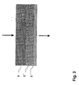
- a filled with hollow metal balls made of a nickel-chromium steel region 3 is formed.
- the metal hollow spheres are held within the housing 2 with metal screens, relatively large mesh size, which is smaller than that of the smallest ball diameter, and may be formed as a loose bed, but also in a sintered form as a self-supporting structure.
- the exhaust gas guided through the area 3 filled with hollow spheres can be aftertreated catalytically if the hollow sphere surfaces are doped or coated with a suitable catalytically active material.
- the exhaust gas flow is influenced in such a way that any particles present are agglomerated and the agglomerates formed in the flow direction of the exhaust gas subsequently filled with metal fibers area 5 separated from the exhaust stream and retained, so that largely pollutant and particle-free exhaust gas from the outlet nozzle 6 can be removed.
- a cavity 4 is formed between the region 3 filled with hollow spheres and the region 5 filled with metal fibers, through which the largely laminar exhaust gas flow can enter into the region 5 filled with metal fibers.
- the optionally containing exhaust gas from the region filled with hollow spheres 3 enters a partial region 5 'as a coarse filter.
- the metal fibers are in this portion 5 'selected so that a porosity of 90 to 95%, and a pore size of 100 to 200 microns is present.
- a second portion 5 '' which is separated from the first portion 5 'in a suitable form, permeable to exhaust gas, arranged.
- This subregion 5 has a porosity in the range between 80 and 90% with a pore size between 50 to 100 ⁇ m and ensures a finer separation of smaller particles.
- a third subregion 5 '' ' likewise filled with metal fibers, adjoins, the porosity of which has been set between 60 to 70% and the pore size ⁇ 50 ⁇ m, so that very fine filtering takes place here.
- the device according to the invention can be designed to be relatively variable and, for example, the region 3 filled with hollow spheres can only be used to influence the exhaust gas flow and / or the particle agglomeration favorable for the separation, and the catalytic aftertreatment can be an optional possibility.
- the same material that has been used for the hollow balls and metal fibers can be used, so that no electrochemical potential differences are recorded and also the properties mentioned in the general part of the description are present.
Landscapes
- Chemical & Material Sciences (AREA)
- Engineering & Computer Science (AREA)
- Chemical Kinetics & Catalysis (AREA)
- Combustion & Propulsion (AREA)
- Mechanical Engineering (AREA)
- General Engineering & Computer Science (AREA)
- Materials Engineering (AREA)
- Organic Chemistry (AREA)
- Toxicology (AREA)
- Health & Medical Sciences (AREA)
- Filtering Materials (AREA)
- Filtering Of Dispersed Particles In Gases (AREA)
- Processes For Solid Components From Exhaust (AREA)
- Exhaust Gas After Treatment (AREA)
- Catalysts (AREA)
- Treating Waste Gases (AREA)
Applications Claiming Priority (3)
| Application Number | Priority Date | Filing Date | Title |
|---|---|---|---|
| DE10058580 | 2000-11-18 | ||
| DE10058580A DE10058580B4 (de) | 2000-11-18 | 2000-11-18 | Vorrichtung und Verfahren zur Nachbehandlung von Verbrennungskraftmaschinenabgasen |
| PCT/DE2001/004363 WO2002040837A1 (de) | 2000-11-18 | 2001-11-17 | Vorrichtung und verfahren zur nachbehandlung von verbrennungskraftmaschinenabgasen |
Publications (2)
| Publication Number | Publication Date |
|---|---|
| EP1336034A1 EP1336034A1 (de) | 2003-08-20 |
| EP1336034B1 true EP1336034B1 (de) | 2006-10-04 |
Family
ID=7664653
Family Applications (1)
| Application Number | Title | Priority Date | Filing Date |
|---|---|---|---|
| EP01996674A Expired - Lifetime EP1336034B1 (de) | 2000-11-18 | 2001-11-17 | Vorrichtung und verfahren zur nachbehandlung von verbrennungskraftmaschinenabgasen |
Country Status (11)
| Country | Link |
|---|---|
| US (1) | US6968681B2 (ko) |
| EP (1) | EP1336034B1 (ko) |
| JP (1) | JP2004526091A (ko) |
| KR (1) | KR100852954B1 (ko) |
| AT (1) | ATE341702T1 (ko) |
| AU (1) | AU2002218989A1 (ko) |
| DE (2) | DE10058580B4 (ko) |
| DK (1) | DK1336034T3 (ko) |
| ES (1) | ES2273922T3 (ko) |
| PT (1) | PT1336034E (ko) |
| WO (1) | WO2002040837A1 (ko) |
Families Citing this family (17)
| Publication number | Priority date | Publication date | Assignee | Title |
|---|---|---|---|---|
| JP2004321930A (ja) * | 2003-04-24 | 2004-11-18 | Japan Organo Co Ltd | ケミカルフィルター |
| AU2003304517A1 (en) * | 2003-05-23 | 2005-05-11 | N.V. Bekaert S.A. | Diesel soot particulate filter medium |
| US20060078479A1 (en) * | 2004-10-07 | 2006-04-13 | Caterpillar Inc. | Filter assembly for an exhaust treatment device |
| FR2880063B1 (fr) * | 2004-12-23 | 2007-04-06 | Renault Sas | Filtre a particules comportant un corps poreux dont la masse thermique n'est pas homogene selon la direction longitudinale |
| DE102005040599B4 (de) | 2005-08-19 | 2007-07-05 | Glatt Systemtechnik Gmbh | Verfahren zur Herstellung von Hohlkörpern mit sphärischer gekrümmter Oberfläche, mit dem Verfahren hergestellte Hohlkörper und deren Verwendung |
| CN101360547B (zh) * | 2006-01-09 | 2012-09-12 | Nv贝卡特股份有限公司 | 柴油机炭烟颗粒过滤介质 |
| DE102006047766A1 (de) * | 2006-10-06 | 2008-04-10 | Deutz Ag | Vorrichtung zur Entfernung von Rußpartikeln aus dem Abgasstrom einer Brennkraftmaschine |
| DE102007032126B4 (de) * | 2007-07-03 | 2011-12-22 | Fraunhofer-Gesellschaft zur Förderung der angewandten Forschung e.V. | Vorrichtung und Verfahren zur Reinigung von Industrieabgasen |
| JP2010534119A (ja) * | 2007-07-16 | 2010-11-04 | ナムローゼ・フエンノートシャップ・ベカート・ソシエテ・アノニム | フィルタ媒体 |
| JP2009172550A (ja) * | 2008-01-28 | 2009-08-06 | Fujifilm Corp | 有害物質除去材及び有害物質除去方法 |
| DE102008021299A1 (de) * | 2008-04-21 | 2009-10-29 | Fraunhofer-Gesellschaft zur Förderung der angewandten Forschung e.V. | Katalysator für toxische Kohlenwasserstoffverbindungen und/oder organische Verbindungen sowie Verfahren zu seiner Herstellung |
| DE102009043121B4 (de) * | 2009-09-25 | 2013-09-05 | Nederman Filtration GmbH | Verfahren und Vorrichtung zur Abgasreinigung von Stationär- und Schiffsmotoren |
| KR101177026B1 (ko) * | 2010-02-18 | 2012-08-27 | 임인권 | 매연저감장치 및 매연저감방법 |
| DE102010031986A1 (de) | 2010-07-22 | 2012-01-26 | Fev Motorentechnik Gmbh | Vorrichtung und Verfahren zur Behandlung von partikelhaltigem Abgas |
| CN103033400B (zh) * | 2012-12-14 | 2015-04-29 | 南京信息工程大学 | 一种大气气溶胶细粒子及气态前体物的采集装置 |
| FR3014946B1 (fr) * | 2013-12-18 | 2018-08-17 | Renault S.A.S. | Systeme d'echappement de moteur a combustion interne |
| CN106110792A (zh) * | 2016-07-27 | 2016-11-16 | 太仓旺泰净化设备有限公司 | 一种高温烟气清洁装置及其清洁纤维球 |
Family Cites Families (20)
| Publication number | Priority date | Publication date | Assignee | Title |
|---|---|---|---|---|
| US2956865A (en) * | 1958-02-03 | 1960-10-18 | John E Morris | Exhaust gas purifier |
| US3254966A (en) * | 1962-06-08 | 1966-06-07 | Universal Oil Prod Co | Means for effecting catalytic conversion of exhaust gas streams |
| US3297400A (en) * | 1962-09-11 | 1967-01-10 | Mobil Oil Corp | Catalytic purification of exhaust gases |
| US3180712A (en) * | 1962-12-26 | 1965-04-27 | Universal Oil Prod Co | Two-stage converter-muffler |
| DE1996059U (de) * | 1964-06-24 | 1968-11-07 | Wmf Wuerttemberg Metallwaren | Aggregat zur verbrennung von auspuffgasen |
| US3771969A (en) * | 1971-05-10 | 1973-11-13 | Arvin Ind Inc | Catalytic converter |
| US4106913A (en) * | 1971-09-03 | 1978-08-15 | Toyota Jidosha Kogyo Kabushiki Kaisha | Catalytic converter having vibration-resistant catalyst carrier |
| JPS5130555B2 (ko) * | 1971-09-03 | 1976-09-01 | ||
| US4072471A (en) * | 1974-05-28 | 1978-02-07 | Mobil Oil Corporation | Catalytic converter for removing noxious components from a gaseous stream |
| GB1519343A (en) * | 1974-09-03 | 1978-07-26 | Matsushita Electric Ind Co Ltd | Gas purifying devices |
| US4290785A (en) * | 1979-02-12 | 1981-09-22 | Alldredge Robert L | Dust collector and method of operation |
| US4338284A (en) * | 1979-09-04 | 1982-07-06 | Vinco Sales Corp., Inc. | Exhaust gas purifier |
| US4360957A (en) * | 1980-07-07 | 1982-11-30 | Texaco Inc. | Method for fabricating an exhaust gas treating unit |
| JPS58143111A (ja) * | 1982-02-22 | 1983-08-25 | Tokyo Roki Kk | デイ−ゼル黒煙除去装置 |
| DE3341804A1 (de) | 1983-11-19 | 1985-05-30 | Wilfried 6238 Hofheim Seitz | Katalysatorkoerper fuer abgaskatalysatoren fuer verbrennungsmaschinen und verfahren zu dessen herstellung |
| DE3436443A1 (de) | 1984-10-04 | 1986-04-10 | Gerhard 8177 Bichl Vester | Kugelpaket-abgaskatalysator |
| US4876072A (en) * | 1988-05-16 | 1989-10-24 | Checki Edward T | Catalytic converter with screen enclosure holding pellets under tension |
| GB2259461A (en) * | 1991-09-12 | 1993-03-17 | Ian James Hollingworth | Catalytic converter |
| DE4234436C2 (de) | 1992-10-13 | 1999-12-30 | Friedrich Schaal | Nachrüstkatalysator ungeregelt ohne Lambdasonde und ohne Regeleinrichtung |
| US6428755B1 (en) * | 1999-10-04 | 2002-08-06 | Ford Global Technologies, Inc. | Catalyst assembly for an exhaust gas system |
-
2000
- 2000-11-18 DE DE10058580A patent/DE10058580B4/de not_active Expired - Fee Related
-
2001
- 2001-11-17 AU AU2002218989A patent/AU2002218989A1/en not_active Abandoned
- 2001-11-17 PT PT01996674T patent/PT1336034E/pt unknown
- 2001-11-17 DE DE50111164T patent/DE50111164D1/de not_active Expired - Lifetime
- 2001-11-17 JP JP2002543133A patent/JP2004526091A/ja active Pending
- 2001-11-17 DK DK01996674T patent/DK1336034T3/da active
- 2001-11-17 ES ES01996674T patent/ES2273922T3/es not_active Expired - Lifetime
- 2001-11-17 EP EP01996674A patent/EP1336034B1/de not_active Expired - Lifetime
- 2001-11-17 US US10/416,156 patent/US6968681B2/en not_active Expired - Fee Related
- 2001-11-17 WO PCT/DE2001/004363 patent/WO2002040837A1/de active IP Right Grant
- 2001-11-17 KR KR1020037006690A patent/KR100852954B1/ko not_active IP Right Cessation
- 2001-11-17 AT AT01996674T patent/ATE341702T1/de active
Also Published As
| Publication number | Publication date |
|---|---|
| DE10058580B4 (de) | 2008-06-19 |
| EP1336034A1 (de) | 2003-08-20 |
| KR20030076980A (ko) | 2003-09-29 |
| DE10058580A1 (de) | 2002-06-06 |
| JP2004526091A (ja) | 2004-08-26 |
| ES2273922T3 (es) | 2007-05-16 |
| ATE341702T1 (de) | 2006-10-15 |
| PT1336034E (pt) | 2007-01-31 |
| WO2002040837A1 (de) | 2002-05-23 |
| DE50111164D1 (de) | 2006-11-16 |
| AU2002218989A1 (en) | 2002-05-27 |
| DK1336034T3 (da) | 2007-02-05 |
| US6968681B2 (en) | 2005-11-29 |
| KR100852954B1 (ko) | 2008-08-19 |
| US20040065079A1 (en) | 2004-04-08 |
Similar Documents
| Publication | Publication Date | Title |
|---|---|---|
| EP1336034B1 (de) | Vorrichtung und verfahren zur nachbehandlung von verbrennungskraftmaschinenabgasen | |
| DE602004011176T2 (de) | Vorrichtung zum Filtern und Brennen von Teilchenmaterial | |
| DE602004005899T2 (de) | Abgassystem mit partikelfilter für einen magermotor | |
| DE3538107A1 (de) | Filter zur reinigung von abgasen | |
| DE102005023518A1 (de) | Verstopfungsfreies Filteraggregat mit hohem Wirkungsgrad | |
| DE60212245T2 (de) | Verfahren und Vorrichtung zum Entfernen von Russpartikeln aus dem Abgas eines Dieselmotors | |
| EP1527262B1 (de) | Abgasfilter und verfahren zum reinigen eines abgases | |
| EP1861608B1 (de) | Abgasanlage mit einer abgasbehandlungseinheit und einem wärmetauscher in einer abgasrückführleitung | |
| WO2007079833A1 (de) | Partikelfilter für eine abgasanlage | |
| DE112008003152B4 (de) | Metallfaserfilter zur Reinigung von Abgas mit einem schlitzartigen Umleitungsteil | |
| DE102013000247A1 (de) | Abgasanlage für eine Verbrennungskraftmaschine und Kraftfahrzeug mit einer solchen | |
| DE102008003044B4 (de) | Abgasreinigungssystem zur verbesserten Abgasreinigung durch konvektives Mischen | |
| EP2699770B1 (de) | Partikelfilter mit katalytischer beschichtung | |
| DE102007036254A1 (de) | Abgasanlage einer Brennkraftmaschine | |
| DE102005032954B4 (de) | Partikelfilter für Abgase | |
| EP1371827B1 (de) | Abgasanlage mit Partikelfilter für Dieselmotoren | |
| WO2007134898A1 (de) | Filtereinrichtung, insbesondere für ein abgassystem einer brennkraftmaschine | |
| DE19933442B4 (de) | Partikelfilter mit einem Filtermedium und einem Katalysator | |
| DE3600373A1 (de) | Partikelfiltersystem fuer gasfoermige medien | |
| DE102010008273B4 (de) | Partikelfilteranordnung | |
| EP2146062B1 (de) | Partikelfilter für Diesel- und Otto-Motoren | |
| EP2069616B1 (de) | Vorrichtung zur entfernung von russpartikeln aus dem abgasstrom einer brennkraftmaschine | |
| AT501042A4 (de) | Vorrichtung zum reinigen von kraftfahrzeugabgasen | |
| DE102007002840A1 (de) | Abgasanlage für einen Kolbenmotor | |
| DE102006041979A1 (de) | Filterelement, insbesondere zur Filterung von Abgasen einer Brennkraftmaschine |
Legal Events
| Date | Code | Title | Description |
|---|---|---|---|
| PUAI | Public reference made under article 153(3) epc to a published international application that has entered the european phase |
Free format text: ORIGINAL CODE: 0009012 |
|
| 17P | Request for examination filed |
Effective date: 20030611 |
|
| AK | Designated contracting states |
Designated state(s): AT BE CH CY DE DK ES FI FR GB GR IE IT LI LU MC NL PT SE TR |
|
| AX | Request for extension of the european patent |
Extension state: AL LT LV MK RO SI |
|
| RAP1 | Party data changed (applicant data changed or rights of an application transferred) |
Owner name: HOCHSCHULE FUER TECHNIK UND WIRTSCHAFT DRESDEN (FH Owner name: FRAUNHOFER-GESELLSCHAFT ZUR FOERDERUNG DERANGEWAND Owner name: GLATT SYSTEMTECHNIK DRESDEN GMBH |
|
| 17Q | First examination report despatched |
Effective date: 20050207 |
|
| GRAP | Despatch of communication of intention to grant a patent |
Free format text: ORIGINAL CODE: EPIDOSNIGR1 |
|
| GRAS | Grant fee paid |
Free format text: ORIGINAL CODE: EPIDOSNIGR3 |
|
| GRAA | (expected) grant |
Free format text: ORIGINAL CODE: 0009210 |
|
| AK | Designated contracting states |
Kind code of ref document: B1 Designated state(s): AT BE CH CY DE DK ES FI FR GB GR IE IT LI LU MC NL PT SE TR |
|
| PG25 | Lapsed in a contracting state [announced via postgrant information from national office to epo] |
Ref country code: IT Free format text: LAPSE BECAUSE OF FAILURE TO SUBMIT A TRANSLATION OF THE DESCRIPTION OR TO PAY THE FEE WITHIN THE PRESCRIBED TIME-LIMIT;WARNING: LAPSES OF ITALIAN PATENTS WITH EFFECTIVE DATE BEFORE 2007 MAY HAVE OCCURRED AT ANY TIME BEFORE 2007. THE CORRECT EFFECTIVE DATE MAY BE DIFFERENT FROM THE ONE RECORDED. Effective date: 20061004 Ref country code: FI Free format text: LAPSE BECAUSE OF FAILURE TO SUBMIT A TRANSLATION OF THE DESCRIPTION OR TO PAY THE FEE WITHIN THE PRESCRIBED TIME-LIMIT Effective date: 20061004 |
|
| REG | Reference to a national code |
Ref country code: GB Ref legal event code: FG4D Free format text: NOT ENGLISH |
|
| REG | Reference to a national code |
Ref country code: CH Ref legal event code: EP |
|
| REG | Reference to a national code |
Ref country code: IE Ref legal event code: FG4D Free format text: LANGUAGE OF EP DOCUMENT: GERMAN |
|
| REF | Corresponds to: |
Ref document number: 50111164 Country of ref document: DE Date of ref document: 20061116 Kind code of ref document: P |
|
| PG25 | Lapsed in a contracting state [announced via postgrant information from national office to epo] |
Ref country code: MC Free format text: LAPSE BECAUSE OF NON-PAYMENT OF DUE FEES Effective date: 20061130 |
|
| REG | Reference to a national code |
Ref country code: CH Ref legal event code: NV Representative=s name: TROESCH SCHEIDEGGER WERNER AG |
|
| REG | Reference to a national code |
Ref country code: SE Ref legal event code: TRGR |
|
| RAP2 | Party data changed (patent owner data changed or rights of a patent transferred) |
Owner name: HOCHSCHULE FUER TECHNIK UND WIRTSCHAFT DRESDEN (FH Owner name: GLATT SYSTEMTECHNIK DRESDEN GMBH Owner name: FRAUNHOFER-GESELLSCHAFT ZUR FOERDERUNG DER ANGEWAN |
|
| GBT | Gb: translation of ep patent filed (gb section 77(6)(a)/1977) |
Effective date: 20070104 |
|
| REG | Reference to a national code |
Ref country code: PT Ref legal event code: SC4A Free format text: AVAILABILITY OF NATIONAL TRANSLATION Effective date: 20061116 |
|
| REG | Reference to a national code |
Ref country code: DK Ref legal event code: T3 |
|
| NLT2 | Nl: modifications (of names), taken from the european patent patent bulletin |
Owner name: FRAUNHOFER-GESELLSCHAFT ZUR EN HOCHSCHULE FUER TEC Effective date: 20070117 |
|
| ET | Fr: translation filed | ||
| REG | Reference to a national code |
Ref country code: ES Ref legal event code: FG2A Ref document number: 2273922 Country of ref document: ES Kind code of ref document: T3 |
|
| PLBE | No opposition filed within time limit |
Free format text: ORIGINAL CODE: 0009261 |
|
| STAA | Information on the status of an ep patent application or granted ep patent |
Free format text: STATUS: NO OPPOSITION FILED WITHIN TIME LIMIT |
|
| 26N | No opposition filed |
Effective date: 20070705 |
|
| PG25 | Lapsed in a contracting state [announced via postgrant information from national office to epo] |
Ref country code: GR Free format text: LAPSE BECAUSE OF FAILURE TO SUBMIT A TRANSLATION OF THE DESCRIPTION OR TO PAY THE FEE WITHIN THE PRESCRIBED TIME-LIMIT Effective date: 20070105 |
|
| PG25 | Lapsed in a contracting state [announced via postgrant information from national office to epo] |
Ref country code: TR Free format text: LAPSE BECAUSE OF FAILURE TO SUBMIT A TRANSLATION OF THE DESCRIPTION OR TO PAY THE FEE WITHIN THE PRESCRIBED TIME-LIMIT Effective date: 20061004 Ref country code: LU Free format text: LAPSE BECAUSE OF NON-PAYMENT OF DUE FEES Effective date: 20061117 |
|
| PG25 | Lapsed in a contracting state [announced via postgrant information from national office to epo] |
Ref country code: CY Free format text: LAPSE BECAUSE OF FAILURE TO SUBMIT A TRANSLATION OF THE DESCRIPTION OR TO PAY THE FEE WITHIN THE PRESCRIBED TIME-LIMIT Effective date: 20061004 |
|
| PGFP | Annual fee paid to national office [announced via postgrant information from national office to epo] |
Ref country code: DK Payment date: 20091112 Year of fee payment: 9 Ref country code: IE Payment date: 20091124 Year of fee payment: 9 |
|
| PGFP | Annual fee paid to national office [announced via postgrant information from national office to epo] |
Ref country code: PT Payment date: 20091111 Year of fee payment: 9 |
|
| PGFP | Annual fee paid to national office [announced via postgrant information from national office to epo] |
Ref country code: BE Payment date: 20091224 Year of fee payment: 9 |
|
| REG | Reference to a national code |
Ref country code: PT Ref legal event code: MM4A Free format text: LAPSE DUE TO NON-PAYMENT OF FEES Effective date: 20110517 |
|
| BERE | Be: lapsed |
Owner name: GLATT SYSTEMTECHNIK DRESDEN G.M.B.H. Effective date: 20101130 Owner name: HOCHSCHULE FUR TECHNIK UND WIRTSCHAFT DRESDEN (FH) Effective date: 20101130 Owner name: FRAUNHOFER-GESELLSCHAFT ZUR FORDERUNG DER ANGEWAN Effective date: 20101130 |
|
| REG | Reference to a national code |
Ref country code: DK Ref legal event code: EBP |
|
| PG25 | Lapsed in a contracting state [announced via postgrant information from national office to epo] |
Ref country code: PT Free format text: LAPSE BECAUSE OF NON-PAYMENT OF DUE FEES Effective date: 20110517 |
|
| PG25 | Lapsed in a contracting state [announced via postgrant information from national office to epo] |
Ref country code: BE Free format text: LAPSE BECAUSE OF NON-PAYMENT OF DUE FEES Effective date: 20101130 |
|
| PG25 | Lapsed in a contracting state [announced via postgrant information from national office to epo] |
Ref country code: DK Free format text: LAPSE BECAUSE OF NON-PAYMENT OF DUE FEES Effective date: 20101130 Ref country code: IE Free format text: LAPSE BECAUSE OF NON-PAYMENT OF DUE FEES Effective date: 20101117 |
|
| REG | Reference to a national code |
Ref country code: DE Ref legal event code: R082 Ref document number: 50111164 Country of ref document: DE Representative=s name: PFENNING MEINIG & PARTNER GBR, DE |
|
| PGFP | Annual fee paid to national office [announced via postgrant information from national office to epo] |
Ref country code: AT Payment date: 20131113 Year of fee payment: 13 Ref country code: SE Payment date: 20131121 Year of fee payment: 13 Ref country code: DE Payment date: 20131129 Year of fee payment: 13 Ref country code: GB Payment date: 20131120 Year of fee payment: 13 Ref country code: CH Payment date: 20131121 Year of fee payment: 13 Ref country code: FR Payment date: 20131120 Year of fee payment: 13 |
|
| REG | Reference to a national code |
Ref country code: DE Ref legal event code: R081 Ref document number: 50111164 Country of ref document: DE Owner name: GLATT SYSTEMTECHNIK GMBH, DE Free format text: FORMER OWNER: FRAUNHOFER-GESELLSCHAFT ZUR FOER, HOCHSCHULE FUER TECHNIK UND WIRT, GLATT SYSTEMTECHNIK GMBH, , DE Effective date: 20131217 Ref country code: DE Ref legal event code: R082 Ref document number: 50111164 Country of ref document: DE Representative=s name: PFENNING MEINIG & PARTNER GBR, DE Effective date: 20131217 Ref country code: DE Ref legal event code: R082 Ref document number: 50111164 Country of ref document: DE Representative=s name: PFENNING, MEINIG & PARTNER MBB PATENTANWAELTE, DE Effective date: 20131217 Ref country code: DE Ref legal event code: R081 Ref document number: 50111164 Country of ref document: DE Owner name: GLATT SYSTEMTECHNIK GMBH, DE Free format text: FORMER OWNERS: FRAUNHOFER-GESELLSCHAFT ZUR FOERDERUNG DER ANGEWANDTEN FORSCHUNG E.V., 80686 MUENCHEN, DE; HOCHSCHULE FUER TECHNIK UND WIRTSCHAFT DRESDEN, 01069 DRESDEN, DE; GLATT SYSTEMTECHNIK GMBH, 01277 DRESDEN, DE Effective date: 20131217 |
|
| PGFP | Annual fee paid to national office [announced via postgrant information from national office to epo] |
Ref country code: ES Payment date: 20131128 Year of fee payment: 13 Ref country code: NL Payment date: 20131121 Year of fee payment: 13 Ref country code: IT Payment date: 20131125 Year of fee payment: 13 |
|
| REG | Reference to a national code |
Ref country code: DE Ref legal event code: R119 Ref document number: 50111164 Country of ref document: DE |
|
| REG | Reference to a national code |
Ref country code: NL Ref legal event code: V1 Effective date: 20150601 |
|
| REG | Reference to a national code |
Ref country code: SE Ref legal event code: EUG Ref country code: CH Ref legal event code: PL |
|
| REG | Reference to a national code |
Ref country code: AT Ref legal event code: MM01 Ref document number: 341702 Country of ref document: AT Kind code of ref document: T Effective date: 20141117 |
|
| GBPC | Gb: european patent ceased through non-payment of renewal fee |
Effective date: 20141117 |
|
| PG25 | Lapsed in a contracting state [announced via postgrant information from national office to epo] |
Ref country code: CH Free format text: LAPSE BECAUSE OF NON-PAYMENT OF DUE FEES Effective date: 20141130 Ref country code: SE Free format text: LAPSE BECAUSE OF NON-PAYMENT OF DUE FEES Effective date: 20141118 Ref country code: LI Free format text: LAPSE BECAUSE OF NON-PAYMENT OF DUE FEES Effective date: 20141130 |
|
| REG | Reference to a national code |
Ref country code: FR Ref legal event code: ST Effective date: 20150731 |
|
| PG25 | Lapsed in a contracting state [announced via postgrant information from national office to epo] |
Ref country code: NL Free format text: LAPSE BECAUSE OF NON-PAYMENT OF DUE FEES Effective date: 20150601 Ref country code: AT Free format text: LAPSE BECAUSE OF NON-PAYMENT OF DUE FEES Effective date: 20141117 |
|
| PG25 | Lapsed in a contracting state [announced via postgrant information from national office to epo] |
Ref country code: GB Free format text: LAPSE BECAUSE OF NON-PAYMENT OF DUE FEES Effective date: 20141117 Ref country code: DE Free format text: LAPSE BECAUSE OF NON-PAYMENT OF DUE FEES Effective date: 20150602 |
|
| PG25 | Lapsed in a contracting state [announced via postgrant information from national office to epo] |
Ref country code: FR Free format text: LAPSE BECAUSE OF NON-PAYMENT OF DUE FEES Effective date: 20141201 |
|
| REG | Reference to a national code |
Ref country code: ES Ref legal event code: FD2A Effective date: 20151230 |
|
| PG25 | Lapsed in a contracting state [announced via postgrant information from national office to epo] |
Ref country code: IT Free format text: LAPSE BECAUSE OF NON-PAYMENT OF DUE FEES Effective date: 20141117 |
|
| PG25 | Lapsed in a contracting state [announced via postgrant information from national office to epo] |
Ref country code: ES Free format text: LAPSE BECAUSE OF NON-PAYMENT OF DUE FEES Effective date: 20141118 |