EP1336034B1 - Method and device for aftertreatment of exhaust gases from combustion engines - Google Patents
Method and device for aftertreatment of exhaust gases from combustion engines Download PDFInfo
- Publication number
- EP1336034B1 EP1336034B1 EP01996674A EP01996674A EP1336034B1 EP 1336034 B1 EP1336034 B1 EP 1336034B1 EP 01996674 A EP01996674 A EP 01996674A EP 01996674 A EP01996674 A EP 01996674A EP 1336034 B1 EP1336034 B1 EP 1336034B1
- Authority
- EP
- European Patent Office
- Prior art keywords
- filled
- exhaust
- region
- hollow spheres
- exhaust gas
- Prior art date
- Legal status (The legal status is an assumption and is not a legal conclusion. Google has not performed a legal analysis and makes no representation as to the accuracy of the status listed.)
- Expired - Lifetime
Links
- 239000007789 gas Substances 0.000 title claims abstract description 66
- 238000002485 combustion reaction Methods 0.000 title claims abstract description 26
- 238000000034 method Methods 0.000 title claims abstract description 9
- 229910052751 metal Inorganic materials 0.000 claims abstract description 47
- 239000002184 metal Substances 0.000 claims abstract description 47
- 239000002245 particle Substances 0.000 claims abstract description 26
- 238000005054 agglomeration Methods 0.000 claims abstract description 4
- 230000002776 aggregation Effects 0.000 claims abstract description 4
- 230000003197 catalytic effect Effects 0.000 claims description 17
- 239000000463 material Substances 0.000 claims description 7
- 238000001914 filtration Methods 0.000 claims description 6
- PXHVJJICTQNCMI-UHFFFAOYSA-N Nickel Chemical compound [Ni] PXHVJJICTQNCMI-UHFFFAOYSA-N 0.000 claims description 4
- 238000009826 distribution Methods 0.000 claims description 4
- 229910045601 alloy Inorganic materials 0.000 claims description 3
- 239000000956 alloy Substances 0.000 claims description 3
- 229910000838 Al alloy Inorganic materials 0.000 claims description 2
- 229910000951 Aluminide Inorganic materials 0.000 claims description 2
- -1 iron-chromium-aluminium Chemical compound 0.000 claims description 2
- 229910052759 nickel Inorganic materials 0.000 claims description 2
- 230000007423 decrease Effects 0.000 claims 2
- 229910000990 Ni alloy Inorganic materials 0.000 claims 1
- BIJOYKCOMBZXAE-UHFFFAOYSA-N chromium iron nickel Chemical compound [Cr].[Fe].[Ni] BIJOYKCOMBZXAE-UHFFFAOYSA-N 0.000 claims 1
- 239000000835 fiber Substances 0.000 abstract description 28
- 238000000926 separation method Methods 0.000 abstract description 7
- 230000002411 adverse Effects 0.000 abstract description 3
- 230000000694 effects Effects 0.000 abstract description 3
- 238000010276 construction Methods 0.000 abstract description 2
- 239000011324 bead Substances 0.000 abstract 4
- 239000011148 porous material Substances 0.000 description 7
- 239000003054 catalyst Substances 0.000 description 6
- 230000008929 regeneration Effects 0.000 description 5
- 238000011069 regeneration method Methods 0.000 description 5
- 239000004071 soot Substances 0.000 description 5
- 239000011149 active material Substances 0.000 description 3
- 239000011248 coating agent Substances 0.000 description 3
- 238000000576 coating method Methods 0.000 description 3
- 230000002349 favourable effect Effects 0.000 description 3
- KDLHZDBZIXYQEI-UHFFFAOYSA-N Palladium Chemical compound [Pd] KDLHZDBZIXYQEI-UHFFFAOYSA-N 0.000 description 2
- 229910000831 Steel Inorganic materials 0.000 description 2
- 229910010293 ceramic material Inorganic materials 0.000 description 2
- VNNRSPGTAMTISX-UHFFFAOYSA-N chromium nickel Chemical compound [Cr].[Ni] VNNRSPGTAMTISX-UHFFFAOYSA-N 0.000 description 2
- 230000008021 deposition Effects 0.000 description 2
- 239000003344 environmental pollutant Substances 0.000 description 2
- 238000011049 filling Methods 0.000 description 2
- 150000002739 metals Chemical class 0.000 description 2
- 238000012856 packing Methods 0.000 description 2
- BASFCYQUMIYNBI-UHFFFAOYSA-N platinum Chemical compound [Pt] BASFCYQUMIYNBI-UHFFFAOYSA-N 0.000 description 2
- 231100000719 pollutant Toxicity 0.000 description 2
- 230000000717 retained effect Effects 0.000 description 2
- 238000005245 sintering Methods 0.000 description 2
- 239000010959 steel Substances 0.000 description 2
- 229910018487 Ni—Cr Inorganic materials 0.000 description 1
- PNEYBMLMFCGWSK-UHFFFAOYSA-N aluminium oxide Inorganic materials [O-2].[O-2].[O-2].[Al+3].[Al+3] PNEYBMLMFCGWSK-UHFFFAOYSA-N 0.000 description 1
- 238000011001 backwashing Methods 0.000 description 1
- 239000000969 carrier Substances 0.000 description 1
- 239000000919 ceramic Substances 0.000 description 1
- 238000005260 corrosion Methods 0.000 description 1
- 230000007797 corrosion Effects 0.000 description 1
- 238000011161 development Methods 0.000 description 1
- 230000018109 developmental process Effects 0.000 description 1
- 238000005485 electric heating Methods 0.000 description 1
- 230000017525 heat dissipation Effects 0.000 description 1
- 229930195733 hydrocarbon Natural products 0.000 description 1
- 150000002430 hydrocarbons Chemical class 0.000 description 1
- 238000011068 loading method Methods 0.000 description 1
- 238000004519 manufacturing process Methods 0.000 description 1
- 238000012986 modification Methods 0.000 description 1
- 230000004048 modification Effects 0.000 description 1
- 238000013021 overheating Methods 0.000 description 1
- 229910052763 palladium Inorganic materials 0.000 description 1
- 229910052697 platinum Inorganic materials 0.000 description 1
- 229910052703 rhodium Inorganic materials 0.000 description 1
- 239000010948 rhodium Substances 0.000 description 1
- MHOVAHRLVXNVSD-UHFFFAOYSA-N rhodium atom Chemical compound [Rh] MHOVAHRLVXNVSD-UHFFFAOYSA-N 0.000 description 1
- 238000007669 thermal treatment Methods 0.000 description 1
- 238000011144 upstream manufacturing Methods 0.000 description 1
Images

Classifications
-
- F—MECHANICAL ENGINEERING; LIGHTING; HEATING; WEAPONS; BLASTING
- F01—MACHINES OR ENGINES IN GENERAL; ENGINE PLANTS IN GENERAL; STEAM ENGINES
- F01N—GAS-FLOW SILENCERS OR EXHAUST APPARATUS FOR MACHINES OR ENGINES IN GENERAL; GAS-FLOW SILENCERS OR EXHAUST APPARATUS FOR INTERNAL COMBUSTION ENGINES
- F01N3/00—Exhaust or silencing apparatus having means for purifying, rendering innocuous, or otherwise treating exhaust
- F01N3/02—Exhaust or silencing apparatus having means for purifying, rendering innocuous, or otherwise treating exhaust for cooling, or for removing solid constituents of, exhaust
- F01N3/021—Exhaust or silencing apparatus having means for purifying, rendering innocuous, or otherwise treating exhaust for cooling, or for removing solid constituents of, exhaust by means of filters
- F01N3/033—Exhaust or silencing apparatus having means for purifying, rendering innocuous, or otherwise treating exhaust for cooling, or for removing solid constituents of, exhaust by means of filters in combination with other devices
- F01N3/035—Exhaust or silencing apparatus having means for purifying, rendering innocuous, or otherwise treating exhaust for cooling, or for removing solid constituents of, exhaust by means of filters in combination with other devices with catalytic reactors, e.g. catalysed diesel particulate filters
-
- B—PERFORMING OPERATIONS; TRANSPORTING
- B01—PHYSICAL OR CHEMICAL PROCESSES OR APPARATUS IN GENERAL
- B01J—CHEMICAL OR PHYSICAL PROCESSES, e.g. CATALYSIS OR COLLOID CHEMISTRY; THEIR RELEVANT APPARATUS
- B01J35/00—Catalysts, in general, characterised by their form or physical properties
- B01J35/19—Catalysts containing parts with different compositions
-
- B—PERFORMING OPERATIONS; TRANSPORTING
- B01—PHYSICAL OR CHEMICAL PROCESSES OR APPARATUS IN GENERAL
- B01J—CHEMICAL OR PHYSICAL PROCESSES, e.g. CATALYSIS OR COLLOID CHEMISTRY; THEIR RELEVANT APPARATUS
- B01J35/00—Catalysts, in general, characterised by their form or physical properties
- B01J35/50—Catalysts, in general, characterised by their form or physical properties characterised by their shape or configuration
- B01J35/51—Spheres
-
- B—PERFORMING OPERATIONS; TRANSPORTING
- B01—PHYSICAL OR CHEMICAL PROCESSES OR APPARATUS IN GENERAL
- B01J—CHEMICAL OR PHYSICAL PROCESSES, e.g. CATALYSIS OR COLLOID CHEMISTRY; THEIR RELEVANT APPARATUS
- B01J35/00—Catalysts, in general, characterised by their form or physical properties
- B01J35/50—Catalysts, in general, characterised by their form or physical properties characterised by their shape or configuration
- B01J35/58—Fabrics or filaments
-
- F—MECHANICAL ENGINEERING; LIGHTING; HEATING; WEAPONS; BLASTING
- F01—MACHINES OR ENGINES IN GENERAL; ENGINE PLANTS IN GENERAL; STEAM ENGINES
- F01N—GAS-FLOW SILENCERS OR EXHAUST APPARATUS FOR MACHINES OR ENGINES IN GENERAL; GAS-FLOW SILENCERS OR EXHAUST APPARATUS FOR INTERNAL COMBUSTION ENGINES
- F01N3/00—Exhaust or silencing apparatus having means for purifying, rendering innocuous, or otherwise treating exhaust
- F01N3/02—Exhaust or silencing apparatus having means for purifying, rendering innocuous, or otherwise treating exhaust for cooling, or for removing solid constituents of, exhaust
- F01N3/021—Exhaust or silencing apparatus having means for purifying, rendering innocuous, or otherwise treating exhaust for cooling, or for removing solid constituents of, exhaust by means of filters
- F01N3/022—Exhaust or silencing apparatus having means for purifying, rendering innocuous, or otherwise treating exhaust for cooling, or for removing solid constituents of, exhaust by means of filters characterised by specially adapted filtering structure, e.g. honeycomb, mesh or fibrous
- F01N3/0226—Exhaust or silencing apparatus having means for purifying, rendering innocuous, or otherwise treating exhaust for cooling, or for removing solid constituents of, exhaust by means of filters characterised by specially adapted filtering structure, e.g. honeycomb, mesh or fibrous the structure being fibrous
-
- F—MECHANICAL ENGINEERING; LIGHTING; HEATING; WEAPONS; BLASTING
- F01—MACHINES OR ENGINES IN GENERAL; ENGINE PLANTS IN GENERAL; STEAM ENGINES
- F01N—GAS-FLOW SILENCERS OR EXHAUST APPARATUS FOR MACHINES OR ENGINES IN GENERAL; GAS-FLOW SILENCERS OR EXHAUST APPARATUS FOR INTERNAL COMBUSTION ENGINES
- F01N3/00—Exhaust or silencing apparatus having means for purifying, rendering innocuous, or otherwise treating exhaust
- F01N3/08—Exhaust or silencing apparatus having means for purifying, rendering innocuous, or otherwise treating exhaust for rendering innocuous
- F01N3/10—Exhaust or silencing apparatus having means for purifying, rendering innocuous, or otherwise treating exhaust for rendering innocuous by thermal or catalytic conversion of noxious components of exhaust
- F01N3/24—Exhaust or silencing apparatus having means for purifying, rendering innocuous, or otherwise treating exhaust for rendering innocuous by thermal or catalytic conversion of noxious components of exhaust characterised by constructional aspects of converting apparatus
- F01N3/28—Construction of catalytic reactors
- F01N3/2803—Construction of catalytic reactors characterised by structure, by material or by manufacturing of catalyst support
- F01N3/2832—Construction of catalytic reactors characterised by structure, by material or by manufacturing of catalyst support granular, e.g. pellets
-
- F—MECHANICAL ENGINEERING; LIGHTING; HEATING; WEAPONS; BLASTING
- F01—MACHINES OR ENGINES IN GENERAL; ENGINE PLANTS IN GENERAL; STEAM ENGINES
- F01N—GAS-FLOW SILENCERS OR EXHAUST APPARATUS FOR MACHINES OR ENGINES IN GENERAL; GAS-FLOW SILENCERS OR EXHAUST APPARATUS FOR INTERNAL COMBUSTION ENGINES
- F01N2330/00—Structure of catalyst support or particle filter
- F01N2330/08—Granular material
-
- F—MECHANICAL ENGINEERING; LIGHTING; HEATING; WEAPONS; BLASTING
- F01—MACHINES OR ENGINES IN GENERAL; ENGINE PLANTS IN GENERAL; STEAM ENGINES
- F01N—GAS-FLOW SILENCERS OR EXHAUST APPARATUS FOR MACHINES OR ENGINES IN GENERAL; GAS-FLOW SILENCERS OR EXHAUST APPARATUS FOR INTERNAL COMBUSTION ENGINES
- F01N2330/00—Structure of catalyst support or particle filter
- F01N2330/12—Metallic wire mesh fabric or knitting
Definitions
- the invention relates to a device and a method for the aftertreatment of internal combustion engine exhaust gases and in particular for the aftertreatment of exhaust gases of internal combustion engines.
- EP 0 142 722 A2 discloses the use of a packing made of spheres or ball-like bodies of a ceramic material for use in catalytic converters.
- DE 42 34 436 A1 relates to a retrofit catalyst with a filling of ceramic balls.
- the device according to the invention for the aftertreatment of internal combustion engine exhaust gases uses at least one region arranged in the exhaust gas flow, which is filled with hollow spheres and the exhaust gas flows through the intermediate spaces of the hollow spheres, wherein optimal flow conditions can be maintained by the relatively uniform flow guidance.
- These flow conditions have a particularly advantageous effect for particle agglomeration and the agglomerates formed can then be separated more favorably from the exhaust gas in subsequently arranged filter elements, wherein protection against exhaust gas pressure surges for such filters / elements or other elements is also provided.
- the flow conditions and pressure conditions in the exhaust system can be relatively easily calculated for such a region filled with hollow spheres and optimized with respect to the respective internal combustion engine, so that the combustion is not adversely affected by unfavorable back pressure conditions in the exhaust stream.
- Hollow balls can be used particularly advantageously, which on the one hand ensure a considerable mass reduction and on the other hand reduce the noise emission can.
- a certain porosity of the spherical surfaces, but also the spherical shells can be relatively easily adjusted, whereby the surfaces can be increased and also the fluidic surface properties can be positively influenced to make the exhaust aftertreatment more effective.
- a filled with balls or hollow spheres area can be arranged in the exhaust line, the balls are, for example, with metallic sieves whose mesh size is of course smaller than the smallest ball diameter to be seen in the flow direction, with a virtually arbitrary arrangement in the exhaust system is possible in principle However, such an area should be arranged in any case before a possibly to be used particulate filter in the flow direction of the exhaust gas.
- an area filled with balls can advantageously also be arranged in the immediate vicinity of the internal combustion engine, at its exhaust outlets, for example directly in an exhaust manifold, wherein a plurality of such areas can also be arranged in individual exhaust gas lines of such exhaust manifold.
- the balls should consist of a corresponding thermally stable material, preferably metals, because of the good thermal conductivity can be used.
- the balls used can be present as loose fill in the corresponding area, as far as possible almost completely filling it. But it is also possible to produce a punctiform sintered bond of adjacent balls, by a thermal treatment.
- the balls form a self-supporting framework in all cases, so that in addition to the sintering, if necessary, no additional stability and strength-increasing measures are required.
- the ball-filled area may be surrounded by a housing member, except for openings through which the exhaust gas can enter and exit, wherein a variety of materials having sufficient strength and thermal resistance may be used. For example, if a metal housing is used, sufficient heat dissipation is given, so that in conjunction with metal balls and the good heat conduction properties can be exploited.
- the balls or hollow spheres used may be doped or coated at least on their surface with catalytically active materials known per se, so that a catalytic aftertreatment of the exhaust gas is possible.
- the housing in which the ball-filled area is arranged, should have a larger free cross-section than the upstream and downstream exhaust pipe parts in order to ensure favorable flow conditions for the exhaust gas and a relatively small pressure increase in front of the ball-filled area.
- the ball diameters can be selected in the range between 1 and 10 mm, whereby hollow ball wall thicknesses between 0.03 and 1 mm can be selected.
- the porosity of the ball structure can be between 70 to 97%.
- the exhaust gas flow following the ball-filled region is largely laminar, which may have an advantageous effect in particular for a subsequent unit for particle filtration.
- a particularly advantageous particulate filter uses metal fibers with selectable or adjustable porosity and / or pore size distribution, through which the exhaust gas, especially of diesel engines for particle filtration / separation is performed.
- the pore size distribution can be in the range 1 to 500 ⁇ m.
- the particle agglomerates formed in the passage through the ball-filled area can be efficiently retained with such a metal fiber structure, and an exhaust gas that is almost completely particle-free can be discharged to the environment.
- Such a filled with metal fibers area is also thermally stable, so that this is an internal combustion engines near arrangement possible, and also in this area exhaust gas temperatures occur sufficient to cause a sekunder regeneration and an additional power supply for the combustion of soot particles is not required ,
- a graduated structure for such a particulate filter can be chosen very particularly advantageously, that is to say several subregions in the flow direction of the exhaust gas are arranged one after the other, each having different porosities and / or pore size distributions, the pore size of the filter being as small as possible. This is possible by a corresponding metal fiber selection and / or a correspondingly dense or less dense packing of metal fibers.
- the region filled with metal fibers and also the already mentioned partial regions of a graded particle filter can likewise be enclosed by metal screens and the remaining part surrounded by a closed housing, preferably made of a metal.
- the cross-sectional areas of the exit from the ball-filled and inlet areas in the metal fiber-filled areas should be the same size and designed.
- the metal fibers can form a sintered self-supporting structure.
- the porosity of the metal fiber structures used can also be chosen in the range between 70 to 95%, and metal fiber diameters in the range between 0.005 and 0.25 mm can be used.
- Hollow spheres may advantageously consist of chromium-nickel steels, nickel-based alloys, iron-chromium-aluminum alloys and aluminides. Of course, other metals or alloys can be used.
- the metal fibers can also be doped or coated with catalytically active materials, as has already been mentioned for the spheres or hollow spheres, so that not only a particle separation but also a catalytic exhaust aftertreatment can be achieved.
- the areas containing metal fibers also have a relatively low mass and form a self-supporting structure. Due to the possible high porosity, a correspondingly high deposition rate can be achieved.
- the noise emission is also reduced and due to the good thermal conductivity of the metal fibers in conjunction with the low heat capacity is also a good response both in a catalytic aftertreatment, as well as in the automatic backwashing (regeneration) given.
- the explicitly mentioned materials are not only sufficiently strong, stable, thermally resistant, but also highly resistant to corrosion, so that a long service life can be ensured.
- Both the hollow spheres, as well as the metal fibers have inherently a correspondingly high porosity, so that an additional surface-enhancing coating is no longer required and the related disadvantages already mentioned can be eliminated.
- a filled with hollow metal balls made of a nickel-chromium steel region 3 is formed.
- the metal hollow spheres are held within the housing 2 with metal screens, relatively large mesh size, which is smaller than that of the smallest ball diameter, and may be formed as a loose bed, but also in a sintered form as a self-supporting structure.
- the exhaust gas guided through the area 3 filled with hollow spheres can be aftertreated catalytically if the hollow sphere surfaces are doped or coated with a suitable catalytically active material.
- the exhaust gas flow is influenced in such a way that any particles present are agglomerated and the agglomerates formed in the flow direction of the exhaust gas subsequently filled with metal fibers area 5 separated from the exhaust stream and retained, so that largely pollutant and particle-free exhaust gas from the outlet nozzle 6 can be removed.
- a cavity 4 is formed between the region 3 filled with hollow spheres and the region 5 filled with metal fibers, through which the largely laminar exhaust gas flow can enter into the region 5 filled with metal fibers.
- the optionally containing exhaust gas from the region filled with hollow spheres 3 enters a partial region 5 'as a coarse filter.
- the metal fibers are in this portion 5 'selected so that a porosity of 90 to 95%, and a pore size of 100 to 200 microns is present.
- a second portion 5 '' which is separated from the first portion 5 'in a suitable form, permeable to exhaust gas, arranged.
- This subregion 5 has a porosity in the range between 80 and 90% with a pore size between 50 to 100 ⁇ m and ensures a finer separation of smaller particles.
- a third subregion 5 '' ' likewise filled with metal fibers, adjoins, the porosity of which has been set between 60 to 70% and the pore size ⁇ 50 ⁇ m, so that very fine filtering takes place here.
- the device according to the invention can be designed to be relatively variable and, for example, the region 3 filled with hollow spheres can only be used to influence the exhaust gas flow and / or the particle agglomeration favorable for the separation, and the catalytic aftertreatment can be an optional possibility.
- the same material that has been used for the hollow balls and metal fibers can be used, so that no electrochemical potential differences are recorded and also the properties mentioned in the general part of the description are present.
Landscapes
- Chemical & Material Sciences (AREA)
- Engineering & Computer Science (AREA)
- Chemical Kinetics & Catalysis (AREA)
- Mechanical Engineering (AREA)
- General Engineering & Computer Science (AREA)
- Combustion & Propulsion (AREA)
- Materials Engineering (AREA)
- Organic Chemistry (AREA)
- Toxicology (AREA)
- Health & Medical Sciences (AREA)
- Filtering Materials (AREA)
- Filtering Of Dispersed Particles In Gases (AREA)
- Processes For Solid Components From Exhaust (AREA)
- Exhaust Gas After Treatment (AREA)
- Treating Waste Gases (AREA)
- Catalysts (AREA)
Abstract
Description
Die Erfindung betrifft eine Vorrichtung und ein Verfahren zur Nachbehandlung von Verbrennungskraftmaschinenabgasen und hier insbesondere zur Nachbehandlung von Abgasen von Verbrennungsmotoren.The invention relates to a device and a method for the aftertreatment of internal combustion engine exhaust gases and in particular for the aftertreatment of exhaust gases of internal combustion engines.
Dabei besteht in verschiedenen alternativen Modifikationen die Möglichkeit, eine katalytischen Nachbehandlung und/oder eine Filterung von im Abgasstrom enthaltenen Partikeln allein oder in Kombination vorzunehmen.In various alternative modifications, it is possible to carry out a catalytic aftertreatment and / or filtering of particles contained in the exhaust gas flow alone or in combination.
Für die Abgasnachbehandlung von Abgasen aus Verbrennungskraftmaschinen sind verschiedene Möglichkeiten bekannt. Dabei werden zusätzliche Elemente, wie Katalysatoren oder Partikelfilter in einer Abgasleitung angeordnet und die zu behandelnden Abgase durch solche Elemente oder an diesen vorbei geführt, um Schadstoffkomponenten in unschädliche Bestandteile umzuwandeln und Partikel, insbesondere Ruß, der bei der Verbrennung in Dieselmotoren anfällt, zurückzuhalten.For the exhaust aftertreatment of exhaust gases from internal combustion engines, various possibilities are known. In this case, additional elements, such as catalysts or particulate filter in an exhaust pipe arranged and passed the exhaust gases to be treated by such elements or past this, in order to convert pollutant components into harmless components and particulates, especially soot, which is produced during combustion in diesel engines, withhold.
Für die katalytische Nachbehandlung von Abgasen ist es bisher üblich, einen so genannten Katalysator in die Abgasleitung zu integrieren, wobei ein Gebilde verwendet wird, das von Hause aus eine relativ große Oberfläche, die durch eine an sich bekannte Beschichtung noch erhöht worden ist, mit katalytisch wirkenden Materialien, wie z.B. Platin, Rhodium und Palladium zu dotieren bzw. zu belegen.For the catalytic after-treatment of exhaust gases, it has been customary to integrate a so-called catalyst in the exhaust pipe, wherein a structure is used, which has a relatively large surface, which has been increased by a known coating even with catalytic catalytically acting materials, such as Platinum, rhodium and palladium to dope or occupy.
Für die katalytische Wirkung ist jedoch eine Mindesttemperatur erforderlich, die bei den herkömmlichen Systemen bei bestimmten Betriebsregimes erreicht werden kann, da in der Startphase eines Verbrennungsmotors die erforderliche Temperaturerhöhung erst durch das austretende Abgas bewirkt wird. Durch die bisher erforderliche, die wirksame Oberfläche vergrößernde Beschichtung muss eine Überhitzung vermieden werden, da sich diese Schichten bei Überschreiten bestimmter Temperaturen auf- bzw. ablösen können und ein solcher Katalysator demzufolge nicht unmittelbar im Anschluß an den Abgasauslass eines Verbrennungsmotors angeordnet werden kann.For the catalytic effect, however, a minimum temperature is required, which can be achieved in the conventional systems in certain operating regime, since in the starting phase of an internal combustion engine, the required temperature increase is effected only by the exiting exhaust gas. Due to the hitherto required coating which increases the effective surface area, overheating must be avoided since these layers can open or come off when certain temperatures are exceeded and accordingly such a catalyst can not be arranged immediately after the exhaust gas outlet of an internal combustion engine.
Für die Filterung von Partikeln und hier insbesondere Rußpartikeln aus den Abgasen von Verbrennungsmotoren sind die verschiedensten Filtersysteme bekannt, wobei sowohl metallische, wie auch Keramikmaterialien Einsatz finden. Durch die Ablagerung von Rußpartikeln in den bekannten Filtern ist es bisher erforderlich, in mehr oder weniger regelmäßigen Abständen eine so genannte Regeneration durchzuführen, um ein weitestgehendes Zusetzen der Filter und demzufolge auch eine Staudruckerhöhung zu vermeiden. Für eine solche Regeneration wird üblicherweise eine Verbrennung des im Filter separierten Rußes initiiert, wofür eine Energiezufuhr erforderlich ist, was selbstverständlich zu einer Wirkungsgradreduzierung führt, unabhängig davon, ob eine elektrische Beheizung oder die erforderliche Verbrennung unter Zufuhr von brennbaren Kohlenwasserstoffen eingeleitet wird.For the filtration of particles and in particular soot particles from the exhaust gases of internal combustion engines, a variety of filter systems are known, wherein Both metallic, as well as ceramic materials find use. Due to the deposition of soot particles in the known filters, it has hitherto been necessary to carry out a so-called regeneration at more or less regular intervals in order to avoid the greatest possible clogging of the filters and consequently also an increase in the ram pressure. For such a regeneration usually a combustion of the soot separated in the filter is initiated, for which a power supply is required, which of course leads to an efficiency reduction, regardless of whether an electric heating or the required combustion is initiated with the supply of combustible hydrocarbons.
Insbesondere durch die herkömmlichen Partikelfilter werden die Strömungsverhältnisse im Abgasstrom, je nach Beladungszustand des Filtermaterials beeinflusst, so dass in vielen Betriebszeiträumen nicht optimale Verbrennungsverhältnisse, abgasgegendruckbedingt eingehalten werden können.In particular, by the conventional particulate filter, the flow conditions in the exhaust stream, depending on the loading state of the filter material is affected, so that in many operating periods not optimal combustion conditions, exhaust gas back pressure can be maintained.
Außerdem sind die herkömmlichen Systeme sowohl in der Herstellung, wie auch im Betrieb kostenintensiv. Daneben ist aus DE 34 36 443 A1 ein Kugelpaket-Abgaskatalysator bekannt.In addition, the conventional systems are expensive to manufacture as well as in operation. In addition, from DE 34 36 443 A1 a Kugelpaket catalytic converter known.
In US 4,106,913 ist ein Abgaskatalysator mit Katalysatorträgern, die durch Sintern hergestellt werden sollen, beschrieben.US Pat. No. 4,106,913 describes an exhaust gas catalyst with catalyst carriers to be produced by sintering.
Die in GB 2 259 461 A beschriebene Lösung betrifft Abgaskatalysatoren mit Aluminiumoxidkugeln.The solution described in
Aus EP 0 142 722 A2 ist der Einsatz einer Packung aus Kugel oder kugelähnlichen Körpern eines keramischen Materials für den Einsatz in Abgaskatalysatoren bekannt.EP 0 142 722 A2 discloses the use of a packing made of spheres or ball-like bodies of a ceramic material for use in catalytic converters.
Die DE 42 34 436 A1 betrifft einen Nachrüstkatalysator mit einer Füllung von Keramikkugeln.DE 42 34 436 A1 relates to a retrofit catalyst with a filling of ceramic balls.
Aus JP 5843111 ist ein Partikelfilter für Dieselmotore bekannt, bei dem Abgas durch Metallfasern, daran anschließend durch eine katalytische Schicht und dann wieder durch Metallfasern geführt werden soll.From JP 5843111 a particle filter for diesel engines is known in which exhaust gas is to be guided through metal fibers, subsequently through a catalytic layer and then again through metal fibers.
Es ist daher Aufgabe der Erfindung, eine Vorrichtung und ein Verfahren zur Abgasnachbehandlung vorzuschlagen, die einfach aufgebaut, kostengünstig sind sowie die Strömungsverhältnisse im Abgasstrom weniger nachteilig beeinflussen.It is therefore an object of the invention to provide an apparatus and a method for exhaust aftertreatment, which are simple in construction, inexpensive and less adversely affect the flow conditions in the exhaust stream.
Erfindungsgemäß wird diese Aufgabe mit einer Vorrichtung gemäß Anspruch 1 und einem Verfahren, das die Merkmale des Anspruchs 15 aufweist, gelöst. Vorteilhafte Ausgestaltungsformen und Weiterbildungen der Erfindung können mit den in den untergeordneten Ansprüchen genannten Merkmalen erreicht werden.According to the invention this object is achieved with a device according to claim 1 and a method comprising the features of claim 15 solved. Advantageous embodiments and developments of the invention can be achieved with the features mentioned in the subordinate claims.
Die erfindungsgemäße Vorrichtung zur Nachbehandlung von Verbrennungskraftmaschinenabgasen verwendet mindestens einen im Abgasstrom angeordneten Bereich, der mit Hohlkugeln ausgefüllt ist und das Abgas durch die Zwischenräume der Hohlkugeln strömt, wobei optimale Strömungsverhältnisse, durch die relativ gleichmäßige Strömungsführung eingehalten werden können. Diese Strömungsverhältnisse wirken sich besonders vorteilhaft für eine Partikelagglomeration aus und die gebildeten Agglomerate können dann in nachfolgend angeordneten Filterelementen günstiger aus dem Abgas separiert werden, wobei außerdem ein Schutz gegen Abgasdruckstöße für solche Filter/-elemente oder andere Elemente gegeben ist.The device according to the invention for the aftertreatment of internal combustion engine exhaust gases uses at least one region arranged in the exhaust gas flow, which is filled with hollow spheres and the exhaust gas flows through the intermediate spaces of the hollow spheres, wherein optimal flow conditions can be maintained by the relatively uniform flow guidance. These flow conditions have a particularly advantageous effect for particle agglomeration and the agglomerates formed can then be separated more favorably from the exhaust gas in subsequently arranged filter elements, wherein protection against exhaust gas pressure surges for such filters / elements or other elements is also provided.
Die Strömungsbedingungen und Druckverhältnisse im Abgasstrang können für einen solchen mit Hohlkugeln gefüllten Bereich relativ einfach berechnet und bezüglich der jeweiligen Verbrennungskraftmaschine optimiert werden, so dass die Verbrennung durch ungünstige Staudruckverhältnisse im Abgasstrom nicht nachteilig beeinflusst wird.The flow conditions and pressure conditions in the exhaust system can be relatively easily calculated for such a region filled with hollow spheres and optimized with respect to the respective internal combustion engine, so that the combustion is not adversely affected by unfavorable back pressure conditions in the exhaust stream.
Besonders vorteilhaft können Hohlkugeln eingesetzt werden, die zum einen eine erhebliche Massereduzierung sichern und zum anderen die Schallemission reduzieren können.Hollow balls can be used particularly advantageously, which on the one hand ensure a considerable mass reduction and on the other hand reduce the noise emission can.
Außerdem kann relativ einfach eine bestimmte Porosität der Kugeloberflächen, aber auch der Kugelschalen eingestellt werden, wodurch die Oberflächen vergrößert und auch die strömungstechnischen Oberflächeneigenschaften positiv beeinflusst werden können, um die Abgasnachbehandlung effektiver zu gestalten.In addition, a certain porosity of the spherical surfaces, but also the spherical shells can be relatively easily adjusted, whereby the surfaces can be increased and also the fluidic surface properties can be positively influenced to make the exhaust aftertreatment more effective.
Ein mit Kugeln bzw. Hohlkugeln gefüllter Bereich kann im Abgasstrang angeordnet werden, wobei die Kugeln beispielsweise mit metallischen Sieben, deren Maschenweite selbstverständlich kleiner als der kleinste Kugeldurchmesser sein soll, in Strömungsrichtung gesehen, gehalten werden, wobei eine nahezu beliebige Anordnung im Abgasstrang prinzipiell möglich ist, ein solcher Bereich jedoch in jedem Fall vor einem gegebenenfalls zu verwendenden Partikelfilter in Strömungsrichtung des Abgases angeordnet werden soll.A filled with balls or hollow spheres area can be arranged in the exhaust line, the balls are, for example, with metallic sieves whose mesh size is of course smaller than the smallest ball diameter to be seen in the flow direction, with a virtually arbitrary arrangement in the exhaust system is possible in principle However, such an area should be arranged in any case before a possibly to be used particulate filter in the flow direction of the exhaust gas.
Ein mit Kugeln gefüllter Bereich kann aber vorteilhaft auch in unmittelbarer Nähe der Verbrennungskraftmaschine, an dessen Abgasauslässen, beispielsweise unmittelbar in einem Abgaskrümmer angeordnet sein, wobei auch mehrere solcher Bereiche in einzelnen Abgassträngen eines solchen Abgaskrümmers angeordnet sein können.However, an area filled with balls can advantageously also be arranged in the immediate vicinity of the internal combustion engine, at its exhaust outlets, for example directly in an exhaust manifold, wherein a plurality of such areas can also be arranged in individual exhaust gas lines of such exhaust manifold.
Die Kugeln sollten aus einem entsprechend thermisch stabilen Material bestehen, wobei bevorzugt Metalle, wegen der guten Wärmeleitfähigkeit eingesetzt werden können.The balls should consist of a corresponding thermally stable material, preferably metals, because of the good thermal conductivity can be used.
Die verwendeten Kugeln können als lose Schüttung im entsprechenden Bereich, diesen möglichst nahezu vollständig ausfüllend, vorliegen. Es besteht aber auch die Möglichkeit, einen punktuellen Sinterverbund benachbarter Kugeln, durch eine thermische Behandlung herzustellen.The balls used can be present as loose fill in the corresponding area, as far as possible almost completely filling it. But it is also possible to produce a punctiform sintered bond of adjacent balls, by a thermal treatment.
In einem gemeinsamen Bereich können auch Kugeln unterschiedlicher Außendurchmesser eingesetzt werden. Günstiger erscheint es jedoch, mehrere kugelgefüllter Bereiche in einer Reihenanordnung einzusetzen, wobei in den einzelnen Bereichen Kugeln mit nahezu gleichem Außendurchmesser enthalten sind, deren Außendurchmesser sich in Strömungsrichtung des Abgases graduiert verkleinern oder vergrößern kann.In a common area and balls of different outer diameter can be used. However, it seems more favorable to use a plurality of ball-filled regions in a row arrangement, wherein spheres with almost the same outer diameter are contained in the individual regions, the outer diameter of which can graduate or enlarge graduated in the flow direction of the exhaust gas.
Die Kugeln bilden aber in allen Fällen ein selbsttragendes Gerüst, so dass neben dem gegebenenfalls vorgenommenen Sintern keine zusätzlichen stabilitäts- und festigkeitserhöhenden Maßnahmen erforderlich sind.However, the balls form a self-supporting framework in all cases, so that in addition to the sintering, if necessary, no additional stability and strength-increasing measures are required.
Der kugelgefüllte Bereich kann von einem Gehäuseelement, bis auf Öffnungen, durch die das Abgas ein- und austreten kann, umgeben sein, wobei die unterschiedlichsten Materialien mit ausreichender Festigkeit und thermischer Beständigkeit verwendet werden können. Wird beispielsweise ein Metallgehäuse verwendet, ist auch eine ausreichende Wärmeabführung gegeben, so dass in Verbindung mit Metallkugeln auch die guten Wärmeleiteigenschaften ausgenutzt werden kann.The ball-filled area may be surrounded by a housing member, except for openings through which the exhaust gas can enter and exit, wherein a variety of materials having sufficient strength and thermal resistance may be used. For example, if a metal housing is used, sufficient heat dissipation is given, so that in conjunction with metal balls and the good heat conduction properties can be exploited.
Die verwendeten Kugeln bzw. Hohlkugeln können zumindestens an ihrer Oberfläche mit an sich bekannten katalytisch wirkenden Materialien dotiert bzw. beschichtet sein, so dass eine katalytische Nachbehandlung des Abgases möglich ist.The balls or hollow spheres used may be doped or coated at least on their surface with catalytically active materials known per se, so that a catalytic aftertreatment of the exhaust gas is possible.
Durch die bereits erwähnte mögliche Anordnung eines kugelgefüllten Bereiches in unmittelbarer Nähe der Abgasauslässe einer Verbrennungskraftmaschine werden die für die katalytische Wirkung erforderlichen Temperaturen schneller erreicht, als dies bei herkömmlichen Systemen der Fall ist. Das Ansprechverhalten kann außerdem durch die relativ kleine Wärmekapazität, insbesondere bei der Verwendung von metallischen Hohlkugeln verbessert werden.By the already mentioned possible arrangement of a ball-filled area in the immediate vicinity of the exhaust gas outlets of an internal combustion engine, the temperatures required for the catalytic effect are reached faster than is the case with conventional systems. The response can also be improved by the relatively small heat capacity, especially when using metallic hollow spheres.
Das Gehäuse, in dem der kugelgefüllte Bereich angeordnet ist, sollte einen größeren freien Querschnitt aufweisen, als die in Strömungsrichtung vor- und nachgeordneten Abgasleitungsteile, um günstige Strömungsverhältnisse für das Abgas und eine relativ kleine Druckerhöhung vor dem kugelgefüllten Bereich zu sichern.The housing, in which the ball-filled area is arranged, should have a larger free cross-section than the upstream and downstream exhaust pipe parts in order to ensure favorable flow conditions for the exhaust gas and a relatively small pressure increase in front of the ball-filled area.
Die Kugeldurchmesser können im Bereich zwischen 1 und 10 mm ausgewählt werden, wobei Hohlkugelwandstärken zwischen 0,03 und 1 mm gewählt werden können. Die Porosität der Kugelstruktur kann zwischen 70 bis 97 % liegen.The ball diameters can be selected in the range between 1 and 10 mm, whereby hollow ball wall thicknesses between 0.03 and 1 mm can be selected. The porosity of the ball structure can be between 70 to 97%.
Neben der gezielten Beeinflussung der Druckverhältnisse des Abgasstromes ist es vorteilhaft, dass die Abgasströmung im Anschluss an den kugelgefüllten Bereich weitestgehend laminar ist, was sich insbesondere für eine nachfolgende Einheit zur Partikelfiltration vorteilhaft auswirken kann.In addition to the targeted influencing of the pressure conditions of the exhaust gas flow, it is advantageous that the exhaust gas flow following the ball-filled region is largely laminar, which may have an advantageous effect in particular for a subsequent unit for particle filtration.
So kann in Strömungsrichtung des Abgases nachfolgend ein weiteres katalytisch wirkendes Element, aber auch ein bereits erwähnter Partikelfilter angeordnet werden.Thus, in the flow direction of the exhaust gas, a further catalytically active element, but also an already mentioned particle filter can be arranged below.
Ein besonders vorteilhafter Partikelfilter verwendet Metallfasern mit auswähl- bzw. einstellbarer Porosität und/oder Porengrößenverteilung, durch die das Abgas, insbesondere von Dieselmotoren zur Partikelfiltration/-separation geführt wird. Die Porengrößenverteilung kann im Bereich 1 bis 500 µm liegen.A particularly advantageous particulate filter uses metal fibers with selectable or adjustable porosity and / or pore size distribution, through which the exhaust gas, especially of diesel engines for particle filtration / separation is performed. The pore size distribution can be in the range 1 to 500 μm.
Die bei der Durchführung durch den kugelgefüllten Bereich gebildeten Partikelagglomerate können mit einer solchen Metallfaserstruktur effizient zurückgehalten und ein nahezu vollständig partikelfreies Abgas kann an die Umwelt abgegeben werden.The particle agglomerates formed in the passage through the ball-filled area can be efficiently retained with such a metal fiber structure, and an exhaust gas that is almost completely particle-free can be discharged to the environment.
Ein solcher mit Metallfasern gefüllter Bereich ist ebenfalls thermisch beständig, so dass auch hierfür eine Verbrennungskraftmaschinen nahe Anordnung möglich ist, und auch in diesem Bereich Abgastemperaturen auftreten, die ausreichen, um eine selbstätige Regeneration zu bewirken und eine zusätzliche Energiezufuhr zur Verbrennung von Rußpartikeln nicht erforderlich ist.Such a filled with metal fibers area is also thermally stable, so that this is an internal combustion engines near arrangement possible, and also in this area exhaust gas temperatures occur sufficient to cause a selbstätige regeneration and an additional power supply for the combustion of soot particles is not required ,
Ganz besonders vorteilhaft kann ein gradierter Aufbau für einen solchen Partikelfilter gewählt werden, d.h., es werden mehrere Teilbereiche in Strömungsrichtung des Abgases nacheinander angeordnet, die jeweils unterschiedliche Porositäten und/oder Porengrößenverteilung aufweisen, wobei die Porengröße des Filters möglichst kleiner wird. Dies ist durch eine entsprechende Metallfaserauswahl und/oder eine entsprechend dichte bzw. weniger dichte Packung von Metallfasern möglich.A graduated structure for such a particulate filter can be chosen very particularly advantageously, that is to say several subregions in the flow direction of the exhaust gas are arranged one after the other, each having different porosities and / or pore size distributions, the pore size of the filter being as small as possible. This is possible by a corresponding metal fiber selection and / or a correspondingly dense or less dense packing of metal fibers.
Der mit Metallfasern gefüllte Bereich und auch die bereits erwähnten Teilbereiche eines gradierten Partikelfilters können ebenfalls von Metallsieben eingeschlossen und der übrige Teil von einem geschlossenen, bevorzugt aus einem Metall bestehenden Gehäuse umgeben sein. Die Querschnittsflächen des Austritts aus dem mit Kugeln befüllten und die des Eintritts in den mit Metallfasern befüllten Bereichen sollten gleich groß und gestaltet sein.The region filled with metal fibers and also the already mentioned partial regions of a graded particle filter can likewise be enclosed by metal screens and the remaining part surrounded by a closed housing, preferably made of a metal. The cross-sectional areas of the exit from the ball-filled and inlet areas in the metal fiber-filled areas should be the same size and designed.
Die Metallfasern können eine versinterte stelbsttragende Struktur bilden.The metal fibers can form a sintered self-supporting structure.
Die Porosität der verwendeten Metallfaserstrukturen kann ebenfalls im Bereich zwischen 70 bis 95 % gewählt bzw. eingestellt werden und es können Metallfaserdurchmesser im Bereich zwischen 0,005 und 0,25 mm eingesetzt werden.The porosity of the metal fiber structures used can also be chosen in the range between 70 to 95%, and metal fiber diameters in the range between 0.005 and 0.25 mm can be used.
Sowohl die Metallfasern, wie auch die Kugeln bzw.Both the metal fibers, as well as the balls or
Hohlkugeln können vorteilhaft aus Chrom-Nickelstählen, Nickel-Basislegierungen, Eisen-Chrom-Aluminiumlegierungen und Aluminiden bestehen. Selbstverständlich können auch andere Metalle bzw. Legierungen eingesetzt werden.Hollow spheres may advantageously consist of chromium-nickel steels, nickel-based alloys, iron-chromium-aluminum alloys and aluminides. Of course, other metals or alloys can be used.
Auch die Metallfasern können, wie dies bereits bei den Kugeln oder Hohlkugeln erwähnt worden ist, mit katalytisch wirkenden Materialien dotiert bzw. beschichtet sein, so dass nicht nur eine Partikelseparation, sondern auch eine katalytische Abgasnachbehandlung erreicht werden kann.The metal fibers can also be doped or coated with catalytically active materials, as has already been mentioned for the spheres or hollow spheres, so that not only a particle separation but also a catalytic exhaust aftertreatment can be achieved.
Auch die Metallfasern enthaltenden Bereiche weisen eine relativ geringe Masse auf und bilden eine selbsttragende Struktur. Durch die mögliche hohe Porosität kann eine entsprechend hohe Abscheiderate erreicht werden.The areas containing metal fibers also have a relatively low mass and form a self-supporting structure. Due to the possible high porosity, a correspondingly high deposition rate can be achieved.
Außerdem wird zusätzlich die Schallemission reduziert und durch die gute Wärmeleitfähigkeit der Metallfasern in Verbindung mit der geringen Wärmekapazität ist ein ebenfalls gutes Ansprechverhalten sowohl bei einer katalytischen Nachbehandlung, wie auch bei der selbsttätigen Rückreinigung (Regeneration) gegeben.In addition, the noise emission is also reduced and due to the good thermal conductivity of the metal fibers in conjunction with the low heat capacity is also a good response both in a catalytic aftertreatment, as well as in the automatic backwashing (regeneration) given.
Die explizit genannten Materialien sind nicht nur ausreichend fest, stabil, thermisch beständig, sondern auch in hohem Maße korrosionsbeständig, so dass eine hohe Lebensdauer gewährleistet werden kann.The explicitly mentioned materials are not only sufficiently strong, stable, thermally resistant, but also highly resistant to corrosion, so that a long service life can be ensured.
Eine redundante parallele Anordnung, wie sie bei einigen bekannten Partikelfiltersystemen bisher verwendet wird, ist nicht erforderlich, da keine Pausen, die für eine bisher übliche Regeneration von Partikelfiltern mehr eingehalten werden müssen.A redundant parallel arrangement, as with some known particle filter systems is used so far, is not necessary, since no breaks, which must be respected for a hitherto conventional regeneration of particulate filters more.
Sowohl die Hohlkugeln, wie auch die Metallfasern weisen von Haus aus eine entsprechend hohe Porosität auf, so dass eine zusätzliche Oberflächen vergrößernde Beschichtung nicht mehr erforderlich ist und die diesbezüglichen bereits erwähnten Nachteile behoben werden können.Both the hollow spheres, as well as the metal fibers have inherently a correspondingly high porosity, so that an additional surface-enhancing coating is no longer required and the related disadvantages already mentioned can be eliminated.
Nachfolgend soll die Erfindung beispielhaft näher erläutert werden.The invention will be explained in more detail by way of example in the following.
Dabei zeigen:
- Figur 1
- in schematischer Form einen Aufbau eines Beispiels einer erfindungsgemäßen Vorrichtung;
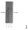
Figur 2- einen in mehrere Teilbereiche unterteilten Bereich zur Partikelseparation, die mit Metallfasern gefüllt sind.
- FIG. 1
- in schematic form a structure of an example of a device according to the invention;
- FIG. 2
- a divided into several subregions area for particle separation, which are filled with metal fibers.
Bei dem in Figur 1 gezeigten Beispiel einer erfindungsgemäßen Vorrichtung zur Nachbehandlung von Verbrennungskraftmaschinenabgasen wird unbehandeltes und ungereinigtes Abgas durch einen Gaseintrittstutzen 1 in ein Metallgehäuse 2 geführt. Dabei vergrößert sich der freie Querschnitt des Gehäuses 2.In the example shown in Figure 1 of a device according to the invention for the aftertreatment of internal combustion engine exhaust gases untreated and unpurified exhaust gas is passed through a gas inlet port 1 in a
Im Gehäuse 2 ist ein mit Metallhohlkugeln, aus einem Nickel-Chromstahl gefüllter Bereich 3 ausgebildet. Die Metallhohlkugeln werden innerhalb des Gehäuses 2 mit Metallsieben, relativ großer Maschenweite, die jedoch kleiner als die des kleinsten Kugeldurchmessers ist, gehalten und können als lose Schüttung, aber auch in versinterter Form als selbsttragende Struktur ausgebildet sein.In the housing 2 a filled with hollow metal balls, made of a nickel-
Das durch den mit Hohlkugeln gefüllten Bereich 3 geführte Abgas kann katalytisch nachbehandelt werden, wenn die Hohlkugeloberflächen mit einem geeigneten katalytisch wirkenden Material dotiert bzw. beschichtet sind.The exhaust gas guided through the
In jedem Fall wird die Abgasströmung jedoch so beeinflusst, dass gegebenenfalls enthaltene Partikel agglomeriert und die gebildeten Agglomerate in der in Strömungsrichtung des Abgases nachfolgend mit Metallfasern befüllten Bereich 5 aus dem Abgasstrom separiert und zurückgehalten werden, so dass weitestgehend schadstoff- und partikelfreies Abgas aus dem Austrittstutzen 6 abgeführt werden kann.In any case, however, the exhaust gas flow is influenced in such a way that any particles present are agglomerated and the agglomerates formed in the flow direction of the exhaust gas subsequently filled with
Bei dem in Figur 1 gezeigten Beispiel einer erfindungsgemäßen Vorrichtung ist zwischen dem mit Hohlkugeln gefüllten Bereich 3 und dem mit Metallfasern befüllten Bereich 5 ein Hohlraum 4 ausgebildet, durch den die weitestgehend laminare Abgasströmung in den mit Metallfasern gefüllten Bereich 5 eintreten kann.In the example of a device according to the invention shown in FIG. 1, a
Bei dem hier gezeigten Beispiel wird ein gradierter Aufbau eines mit Metallfasern befüllten Bereiches 5 verwendet, wobei, wie dies deutlicher der Figur 2 entnommen werden kann, eine dreifache Abstufung gewählt worden ist.In the example shown here is a graded Structure of a region filled with
So tritt das gegebenenfalls Partikel enthaltende Abgas aus dem mit Hohlkugeln befüllten Bereich 3 in einen Teilbereich 5' als Grobfilter ein. Die Metallfasern sind in diesem Teilbereich 5' so gewählt, dass eine Porosität von 90 bis 95 %, sowie eine Porengröße von 100 bis 200 µm vorliegt.Thus, the optionally containing exhaust gas from the region filled with
Anschließend ist mittig ein zweiter Teilbereich 5'', der vom ersten Teilbereich 5' in geeigneter Form, abgasdurchlässig abgetrennt ist, angeordnet. Dieser Teilbereich 5'' weist eine Porosität im Bereich zwischen 80 und 90 % mit einer Porengröße zwischen 50 bis 100 µm auf und sichert eine feinere Separation kleinerer Partikel.Subsequently, in the middle, a second portion 5 '', which is separated from the first portion 5 'in a suitable form, permeable to exhaust gas, arranged. This
In Richtung des Gasaustrittes 6 schließt sich ein dritter Teilbereich 5''', ebenfalls mit Metallfasern gefüllt, an, dessen Porosität zwischen 60 bis 70 % und die Porengröße < 50 µm eingestellt worden ist, so dass hier eine sehr feine Filterung erfolgt.In the direction of the
Selbstverständlich kann auch eine feinere Graduierung mit mehr als den drei gezeigten Teilbereichen 5', 5'', 5''' gewählt werden können.Of course, a finer graduation with more than the three shown subregions 5 ', 5' ', 5' '' can be selected.
In allen, aber auch in lediglich einem oder zwei Teilbereichen 5', 5'' oder 5''' können katalytisch dotiert bzw. beschichtete Metallfasern eingesetzt werden, um eine zusätzliche katalytische Nachbehandlung vorzunehmen.In all, but also in only one or two subregions 5 ', 5''or5''' can catalytically doped or coated metal fibers are used to carry out an additional catalytic aftertreatment.
Die erfindungsgemäße Vorrichtung kann relativ variabel ausgebildet sein und beispielsweise der mit Hohlkugeln gefüllte Bereich 3 lediglich zur Beeinflussung der Abgasströmung und/oder der für die Separation günstigen Partikelagglomeration genutzt werden und die katalytische Nachbehandlung kann eine optionale Möglichkeit sein.The device according to the invention can be designed to be relatively variable and, for example, the
Ähnlich verhält es sich auch mit den mit Metallfasern gefüllten Bereichen 5, die allein für die Partikelseparation aus dem Abgasstrom benutzt werden können, aber auch eine katalytische Nachbehandlung optional gegeben sein kann.The situation is similar with the
Auch für das Gehäuse 2 kann das gleiche Material, das auch für die Hohlkugeln und Metallfasern verwendet worden ist, eingesetzt werden, so dass keine elektrochemischen Potentialdifferenzen zu verzeichnen und auch die im allgemeinen Teil der Beschreibung erwähnten Eigenschaften vorhanden sind.Also for the
Claims (17)
- Device for the aftertreatment of internal combustion engine exhaust gases, in which the exhaust-gas stream is routed through a region (3) filled with hollow spheres and thereafter through a region (5) filled with metal fibres, as a particle filter.
- Device according to Claim 1, characterized in that the hollow spheres consist of a metal.
- Device according to either one of Claims 1 and 2, characterized in that the hollow spheres are porous.
- Device according to one of Claims 1 to 3, characterized in that the sphere diameters decrease in the direction of flow of the exhaust gas.
- Device according to one of Claims 1 to 4, characterized in that the hollow spheres are sintered together with one another in a punctiform manner.
- Device according to one of Claims 1 to 5, characterized in that the region (5) filled with metal fibres is subdivided into at least two layer-shaped subregions with a different porosity and/or pore-size distribution in the direction of flow of the exhaust-gas stream.
- Device according to one of Claims 1 to 6, characterized in that the porosity decreases in the direction of flow of the exhaust gas.
- Device according to one of Claims 1 to 7, characterized in that porosities in the range of between 70 and 95% are maintained.
- Device according to one of Claims 1 to 8, characterized in that the surface of the hollow spheres and/or metal fibres is doped or coated with catalytically acting material.
- Device according to one of Claims 1 to 9, characterized in that the region (3) filled with hollow spheres is arranged near the exhaust-gas outlet of an internal combustion engine.
- Device according to one of Claims 1 to 10, characterized in that the region (3) filled with hollow spheres is arranged in the exhaust manifold of an internal combustion engine.
- Device according to one of Claims 1 to 11, characterized in that a cavity (4) is present between the region (3) filled with hollow spheres and the region (5) filled with metal fibres.
- Device according to one of Claims 1 to 12, characterized in that the free cross section via which the exhaust gas is routed through the regions (3, 4, 5) is enlarged in comparison with the exhaust-gas line.
- Device according to one of Claims 1 to 13, characterized in that the hollow spheres and metal fibres are formed from an iron-chromium-nickel alloy, nickel-based alloy, iron-chromium-aluminium alloy or aluminide or a combination thereof.
- Method for the aftertreatment of internal combustion engine exhaust gases, in which exhaust gas is routed through a region (3) filled with hollow spheres, for influencing the exhaust-gas flow, the particle agglomeration and/or the catalytic aftertreatment of the exhaust gas, and, after the region (3) filled with hollow spheres, the exhaust gas is routed through a region (5) filled with metal fibres, for the filtration of particles out of the exhaust gas and/or for catalytic exhaust-gas aftertreatment.
- Method according to Claim 15, characterized in that, during routing through the region (3) filled with hollow spheres, agglomerated particles are separated out of the exhaust-gas stream in the region (5) filled with metal fibres.
- Method according to either one of Claims 15 and 16, characterized in that, in the region (5) filled with metal fibres, which is subdivided into subregions (5', 5'', 5''') of different porosity, particles are filtered out in a graduated manner.
Applications Claiming Priority (3)
| Application Number | Priority Date | Filing Date | Title |
|---|---|---|---|
| DE10058580 | 2000-11-18 | ||
| DE10058580A DE10058580B4 (en) | 2000-11-18 | 2000-11-18 | Apparatus and method for the aftertreatment of internal combustion engine exhaust gases |
| PCT/DE2001/004363 WO2002040837A1 (en) | 2000-11-18 | 2001-11-17 | Method and device for aftertreatment of exhaust gases from combustion engines |
Publications (2)
| Publication Number | Publication Date |
|---|---|
| EP1336034A1 EP1336034A1 (en) | 2003-08-20 |
| EP1336034B1 true EP1336034B1 (en) | 2006-10-04 |
Family
ID=7664653
Family Applications (1)
| Application Number | Title | Priority Date | Filing Date |
|---|---|---|---|
| EP01996674A Expired - Lifetime EP1336034B1 (en) | 2000-11-18 | 2001-11-17 | Method and device for aftertreatment of exhaust gases from combustion engines |
Country Status (11)
| Country | Link |
|---|---|
| US (1) | US6968681B2 (en) |
| EP (1) | EP1336034B1 (en) |
| JP (1) | JP2004526091A (en) |
| KR (1) | KR100852954B1 (en) |
| AT (1) | ATE341702T1 (en) |
| AU (1) | AU2002218989A1 (en) |
| DE (2) | DE10058580B4 (en) |
| DK (1) | DK1336034T3 (en) |
| ES (1) | ES2273922T3 (en) |
| PT (1) | PT1336034E (en) |
| WO (1) | WO2002040837A1 (en) |
Families Citing this family (17)
| Publication number | Priority date | Publication date | Assignee | Title |
|---|---|---|---|---|
| JP2004321930A (en) * | 2003-04-24 | 2004-11-18 | Japan Organo Co Ltd | Chemical filter |
| WO2005040572A1 (en) * | 2003-05-23 | 2005-05-06 | N.V. Bekaert S.A. | Diesel soot particulate filter medium |
| US20060078479A1 (en) * | 2004-10-07 | 2006-04-13 | Caterpillar Inc. | Filter assembly for an exhaust treatment device |
| FR2880063B1 (en) * | 2004-12-23 | 2007-04-06 | Renault Sas | PARTICLE FILTER COMPRISING A POROUS BODY WHICH THE THERMAL MASS IS NOT HOMOGENEOUS ACCORDING TO THE LONGITUDINAL DIRECTION |
| DE102005040599B4 (en) * | 2005-08-19 | 2007-07-05 | Glatt Systemtechnik Gmbh | A method for the production of hollow bodies with a spherical curved surface, hollow bodies produced by the process and their use |
| EP1979066A1 (en) * | 2006-01-09 | 2008-10-15 | NV Bekaert SA | A diesel soot particulate filter medium |
| DE102006047766A1 (en) * | 2006-10-06 | 2008-04-10 | Deutz Ag | Device for removing soot particles from the exhaust gas stream of an internal combustion engine |
| DE102007032126B4 (en) * | 2007-07-03 | 2011-12-22 | Fraunhofer-Gesellschaft zur Förderung der angewandten Forschung e.V. | Apparatus and process for the purification of industrial waste gases |
| US8449642B2 (en) * | 2007-07-16 | 2013-05-28 | Nv Bekaert Sa | Filter medium |
| JP2009172550A (en) * | 2008-01-28 | 2009-08-06 | Fujifilm Corp | Toxic substance removal material and method for removing toxic substance |
| DE102008021299A1 (en) * | 2008-04-21 | 2009-10-29 | Fraunhofer-Gesellschaft zur Förderung der angewandten Forschung e.V. | Catalyst for toxic hydrocarbon compounds and / or organic compounds and process for its preparation |
| DE102009043121B4 (en) * | 2009-09-25 | 2013-09-05 | Nederman Filtration GmbH | Method and device for exhaust gas purification of stationary and marine engines |
| KR101177026B1 (en) * | 2010-02-18 | 2012-08-27 | 임인권 | Device for Cleaning Soot Particle and Method for the Same |
| DE102010031986A1 (en) | 2010-07-22 | 2012-01-26 | Fev Motorentechnik Gmbh | Apparatus for treatment of exhaust gas particles, particularly for internal combustion engine, has particle agglomeration arrangement with flow guiding surface for guiding of exhaust gas |
| CN103033400B (en) * | 2012-12-14 | 2015-04-29 | 南京信息工程大学 | Collection device of fine atomospheric aerosol particle and gaseous precursor |
| FR3014946B1 (en) * | 2013-12-18 | 2018-08-17 | Renault S.A.S. | INTERNAL COMBUSTION ENGINE EXHAUST SYSTEM |
| CN106110792A (en) * | 2016-07-27 | 2016-11-16 | 太仓旺泰净化设备有限公司 | A kind of high-temperature flue gas cleaning device and cleaning fibrous nodules thereof |
Family Cites Families (20)
| Publication number | Priority date | Publication date | Assignee | Title |
|---|---|---|---|---|
| US2956865A (en) * | 1958-02-03 | 1960-10-18 | John E Morris | Exhaust gas purifier |
| US3254966A (en) | 1962-06-08 | 1966-06-07 | Universal Oil Prod Co | Means for effecting catalytic conversion of exhaust gas streams |
| US3297400A (en) * | 1962-09-11 | 1967-01-10 | Mobil Oil Corp | Catalytic purification of exhaust gases |
| US3180712A (en) * | 1962-12-26 | 1965-04-27 | Universal Oil Prod Co | Two-stage converter-muffler |
| DE1996059U (en) * | 1964-06-24 | 1968-11-07 | Wmf Wuerttemberg Metallwaren | UNIT FOR COMBUSTION OF EXHAUST GASES |
| US3771969A (en) * | 1971-05-10 | 1973-11-13 | Arvin Ind Inc | Catalytic converter |
| US4106913A (en) * | 1971-09-03 | 1978-08-15 | Toyota Jidosha Kogyo Kabushiki Kaisha | Catalytic converter having vibration-resistant catalyst carrier |
| JPS5130555B2 (en) * | 1971-09-03 | 1976-09-01 | ||
| US4072471A (en) * | 1974-05-28 | 1978-02-07 | Mobil Oil Corporation | Catalytic converter for removing noxious components from a gaseous stream |
| GB1519343A (en) * | 1974-09-03 | 1978-07-26 | Matsushita Electric Ind Co Ltd | Gas purifying devices |
| US4290785A (en) * | 1979-02-12 | 1981-09-22 | Alldredge Robert L | Dust collector and method of operation |
| US4338284A (en) * | 1979-09-04 | 1982-07-06 | Vinco Sales Corp., Inc. | Exhaust gas purifier |
| US4360957A (en) * | 1980-07-07 | 1982-11-30 | Texaco Inc. | Method for fabricating an exhaust gas treating unit |
| JPS58143111A (en) * | 1982-02-22 | 1983-08-25 | Tokyo Roki Kk | Black smoke removing device for diesel engine |
| DE3341804A1 (en) * | 1983-11-19 | 1985-05-30 | Wilfried 6238 Hofheim Seitz | CATALYST BODY FOR EXHAUST GAS CATALYSTS FOR COMBUSTION ENGINES AND METHOD FOR THE PRODUCTION THEREOF |
| DE3436443A1 (en) * | 1984-10-04 | 1986-04-10 | Gerhard 8177 Bichl Vester | Bead package exhaust gas catalyst |
| US4876072A (en) * | 1988-05-16 | 1989-10-24 | Checki Edward T | Catalytic converter with screen enclosure holding pellets under tension |
| GB2259461A (en) * | 1991-09-12 | 1993-03-17 | Ian James Hollingworth | Catalytic converter |
| DE4234436C2 (en) * | 1992-10-13 | 1999-12-30 | Friedrich Schaal | Retrofit catalytic converter unregulated without lambda probe and without control device |
| US6428755B1 (en) * | 1999-10-04 | 2002-08-06 | Ford Global Technologies, Inc. | Catalyst assembly for an exhaust gas system |
-
2000
- 2000-11-18 DE DE10058580A patent/DE10058580B4/en not_active Expired - Fee Related
-
2001
- 2001-11-17 ES ES01996674T patent/ES2273922T3/en not_active Expired - Lifetime
- 2001-11-17 EP EP01996674A patent/EP1336034B1/en not_active Expired - Lifetime
- 2001-11-17 DE DE50111164T patent/DE50111164D1/en not_active Expired - Lifetime
- 2001-11-17 AU AU2002218989A patent/AU2002218989A1/en not_active Abandoned
- 2001-11-17 DK DK01996674T patent/DK1336034T3/en active
- 2001-11-17 WO PCT/DE2001/004363 patent/WO2002040837A1/en active IP Right Grant
- 2001-11-17 PT PT01996674T patent/PT1336034E/en unknown
- 2001-11-17 JP JP2002543133A patent/JP2004526091A/en active Pending
- 2001-11-17 KR KR1020037006690A patent/KR100852954B1/en not_active IP Right Cessation
- 2001-11-17 US US10/416,156 patent/US6968681B2/en not_active Expired - Fee Related
- 2001-11-17 AT AT01996674T patent/ATE341702T1/en active
Also Published As
| Publication number | Publication date |
|---|---|
| KR20030076980A (en) | 2003-09-29 |
| US6968681B2 (en) | 2005-11-29 |
| DE10058580B4 (en) | 2008-06-19 |
| EP1336034A1 (en) | 2003-08-20 |
| DE10058580A1 (en) | 2002-06-06 |
| US20040065079A1 (en) | 2004-04-08 |
| AU2002218989A1 (en) | 2002-05-27 |
| WO2002040837A1 (en) | 2002-05-23 |
| PT1336034E (en) | 2007-01-31 |
| DK1336034T3 (en) | 2007-02-05 |
| ES2273922T3 (en) | 2007-05-16 |
| DE50111164D1 (en) | 2006-11-16 |
| JP2004526091A (en) | 2004-08-26 |
| KR100852954B1 (en) | 2008-08-19 |
| ATE341702T1 (en) | 2006-10-15 |
Similar Documents
| Publication | Publication Date | Title |
|---|---|---|
| EP1336034B1 (en) | Method and device for aftertreatment of exhaust gases from combustion engines | |
| DE69514608T2 (en) | Particle filter | |
| DE69216101T2 (en) | PARTICLE FILTER FOR PURIFYING DIESEL ENGINE EXHAUST GAS | |
| DE602004011176T2 (en) | Apparatus for filtering and burning particulate matter | |
| DE602004005899T2 (en) | EXHAUST SYSTEM WITH PARTICLE FILTER FOR A MAGIC MOTOR | |
| DE3538107A1 (en) | EXHAUST GAS FILTER | |
| DE102005023518A1 (en) | Blockage-free filter unit with high efficiency | |
| DE60212245T2 (en) | Method and device for removing soot particles from the exhaust gas of a diesel engine | |
| EP1527262B1 (en) | Exhaust gas filter and method for cleaning an exhaust gas | |
| EP1861608B1 (en) | Exhaust system with an exhaust gas treatment unit and a heat exchanger in an exhaust recycle line | |
| WO2007079833A1 (en) | Particulate filter for an exhaust system | |
| DE102013000247A1 (en) | Exhaust gas system for internal combustion engine e.g. diesel engine of motor car, has screen-like filter element that is formed between motor-side end and exhaust gas recirculation (EGR) valve | |
| DE102008003044B4 (en) | Emission control system for improved exhaust gas purification by convective mixing | |
| EP2699770B1 (en) | Particle filter provided with a catalytic coating | |
| DE19933442B4 (en) | Particle filter with a filter medium and a catalyst | |
| DE102007036254A1 (en) | Exhaust system of an internal combustion engine | |
| DE102005032954B4 (en) | Particulate filter for exhaust gases | |
| EP1371827B1 (en) | Exhaust system with particle filter for a diesel engine | |
| EP2026894A1 (en) | Filter device, especially for an exhaust system of an internal combustion engine | |
| DE3600373A1 (en) | PARTICLE FILTER SYSTEM FOR GASEOUS MEDIA | |
| DE102010008273B4 (en) | particulate filter assembly | |
| EP2146062B1 (en) | Particulate filter for diesel and petrol engines | |
| EP2069616B1 (en) | Device for removing soot particles from the exhaust gas flow of an internal combustion engine | |
| AT501042A4 (en) | Motor vehicle exhaust gas purifying device, has purification module arranged within housing in such a manner that discharged streams flows through purification module to outlet, and gas porous metal foam body connected upstream of module | |
| DE102007002840A1 (en) | Exhaust system for a piston engine |
Legal Events
| Date | Code | Title | Description |
|---|---|---|---|
| PUAI | Public reference made under article 153(3) epc to a published international application that has entered the european phase |
Free format text: ORIGINAL CODE: 0009012 |
|
| 17P | Request for examination filed |
Effective date: 20030611 |
|
| AK | Designated contracting states |
Designated state(s): AT BE CH CY DE DK ES FI FR GB GR IE IT LI LU MC NL PT SE TR |
|
| AX | Request for extension of the european patent |
Extension state: AL LT LV MK RO SI |
|
| RAP1 | Party data changed (applicant data changed or rights of an application transferred) |
Owner name: HOCHSCHULE FUER TECHNIK UND WIRTSCHAFT DRESDEN (FH Owner name: FRAUNHOFER-GESELLSCHAFT ZUR FOERDERUNG DERANGEWAND Owner name: GLATT SYSTEMTECHNIK DRESDEN GMBH |
|
| 17Q | First examination report despatched |
Effective date: 20050207 |
|
| GRAP | Despatch of communication of intention to grant a patent |
Free format text: ORIGINAL CODE: EPIDOSNIGR1 |
|
| GRAS | Grant fee paid |
Free format text: ORIGINAL CODE: EPIDOSNIGR3 |
|
| GRAA | (expected) grant |
Free format text: ORIGINAL CODE: 0009210 |
|
| AK | Designated contracting states |
Kind code of ref document: B1 Designated state(s): AT BE CH CY DE DK ES FI FR GB GR IE IT LI LU MC NL PT SE TR |
|
| PG25 | Lapsed in a contracting state [announced via postgrant information from national office to epo] |
Ref country code: IT Free format text: LAPSE BECAUSE OF FAILURE TO SUBMIT A TRANSLATION OF THE DESCRIPTION OR TO PAY THE FEE WITHIN THE PRESCRIBED TIME-LIMIT;WARNING: LAPSES OF ITALIAN PATENTS WITH EFFECTIVE DATE BEFORE 2007 MAY HAVE OCCURRED AT ANY TIME BEFORE 2007. THE CORRECT EFFECTIVE DATE MAY BE DIFFERENT FROM THE ONE RECORDED. Effective date: 20061004 Ref country code: FI Free format text: LAPSE BECAUSE OF FAILURE TO SUBMIT A TRANSLATION OF THE DESCRIPTION OR TO PAY THE FEE WITHIN THE PRESCRIBED TIME-LIMIT Effective date: 20061004 |
|
| REG | Reference to a national code |
Ref country code: GB Ref legal event code: FG4D Free format text: NOT ENGLISH |
|
| REG | Reference to a national code |
Ref country code: CH Ref legal event code: EP |
|
| REG | Reference to a national code |
Ref country code: IE Ref legal event code: FG4D Free format text: LANGUAGE OF EP DOCUMENT: GERMAN |
|
| REF | Corresponds to: |
Ref document number: 50111164 Country of ref document: DE Date of ref document: 20061116 Kind code of ref document: P |
|
| PG25 | Lapsed in a contracting state [announced via postgrant information from national office to epo] |
Ref country code: MC Free format text: LAPSE BECAUSE OF NON-PAYMENT OF DUE FEES Effective date: 20061130 |
|
| REG | Reference to a national code |
Ref country code: CH Ref legal event code: NV Representative=s name: TROESCH SCHEIDEGGER WERNER AG |
|
| REG | Reference to a national code |
Ref country code: SE Ref legal event code: TRGR |
|
| RAP2 | Party data changed (patent owner data changed or rights of a patent transferred) |
Owner name: HOCHSCHULE FUER TECHNIK UND WIRTSCHAFT DRESDEN (FH Owner name: GLATT SYSTEMTECHNIK DRESDEN GMBH Owner name: FRAUNHOFER-GESELLSCHAFT ZUR FOERDERUNG DER ANGEWAN |
|
| GBT | Gb: translation of ep patent filed (gb section 77(6)(a)/1977) |
Effective date: 20070104 |
|
| REG | Reference to a national code |
Ref country code: PT Ref legal event code: SC4A Free format text: AVAILABILITY OF NATIONAL TRANSLATION Effective date: 20061116 |
|
| REG | Reference to a national code |
Ref country code: DK Ref legal event code: T3 |
|
| NLT2 | Nl: modifications (of names), taken from the european patent patent bulletin |
Owner name: FRAUNHOFER-GESELLSCHAFT ZUR EN HOCHSCHULE FUER TEC Effective date: 20070117 |
|
| ET | Fr: translation filed | ||
| REG | Reference to a national code |
Ref country code: ES Ref legal event code: FG2A Ref document number: 2273922 Country of ref document: ES Kind code of ref document: T3 |
|
| PLBE | No opposition filed within time limit |
Free format text: ORIGINAL CODE: 0009261 |
|
| STAA | Information on the status of an ep patent application or granted ep patent |
Free format text: STATUS: NO OPPOSITION FILED WITHIN TIME LIMIT |
|
| 26N | No opposition filed |
Effective date: 20070705 |
|
| PG25 | Lapsed in a contracting state [announced via postgrant information from national office to epo] |
Ref country code: GR Free format text: LAPSE BECAUSE OF FAILURE TO SUBMIT A TRANSLATION OF THE DESCRIPTION OR TO PAY THE FEE WITHIN THE PRESCRIBED TIME-LIMIT Effective date: 20070105 |
|
| PG25 | Lapsed in a contracting state [announced via postgrant information from national office to epo] |
Ref country code: TR Free format text: LAPSE BECAUSE OF FAILURE TO SUBMIT A TRANSLATION OF THE DESCRIPTION OR TO PAY THE FEE WITHIN THE PRESCRIBED TIME-LIMIT Effective date: 20061004 Ref country code: LU Free format text: LAPSE BECAUSE OF NON-PAYMENT OF DUE FEES Effective date: 20061117 |
|
| PG25 | Lapsed in a contracting state [announced via postgrant information from national office to epo] |
Ref country code: CY Free format text: LAPSE BECAUSE OF FAILURE TO SUBMIT A TRANSLATION OF THE DESCRIPTION OR TO PAY THE FEE WITHIN THE PRESCRIBED TIME-LIMIT Effective date: 20061004 |
|
| PGFP | Annual fee paid to national office [announced via postgrant information from national office to epo] |
Ref country code: DK Payment date: 20091112 Year of fee payment: 9 Ref country code: IE Payment date: 20091124 Year of fee payment: 9 |
|
| PGFP | Annual fee paid to national office [announced via postgrant information from national office to epo] |
Ref country code: PT Payment date: 20091111 Year of fee payment: 9 |
|
| PGFP | Annual fee paid to national office [announced via postgrant information from national office to epo] |
Ref country code: BE Payment date: 20091224 Year of fee payment: 9 |
|
| REG | Reference to a national code |
Ref country code: PT Ref legal event code: MM4A Free format text: LAPSE DUE TO NON-PAYMENT OF FEES Effective date: 20110517 |
|
| BERE | Be: lapsed |
Owner name: GLATT SYSTEMTECHNIK DRESDEN G.M.B.H. Effective date: 20101130 Owner name: HOCHSCHULE FUR TECHNIK UND WIRTSCHAFT DRESDEN (FH) Effective date: 20101130 Owner name: FRAUNHOFER-GESELLSCHAFT ZUR FORDERUNG DER ANGEWAN Effective date: 20101130 |
|
| REG | Reference to a national code |
Ref country code: DK Ref legal event code: EBP |
|
| PG25 | Lapsed in a contracting state [announced via postgrant information from national office to epo] |
Ref country code: PT Free format text: LAPSE BECAUSE OF NON-PAYMENT OF DUE FEES Effective date: 20110517 |
|
| PG25 | Lapsed in a contracting state [announced via postgrant information from national office to epo] |
Ref country code: BE Free format text: LAPSE BECAUSE OF NON-PAYMENT OF DUE FEES Effective date: 20101130 |
|
| PG25 | Lapsed in a contracting state [announced via postgrant information from national office to epo] |
Ref country code: DK Free format text: LAPSE BECAUSE OF NON-PAYMENT OF DUE FEES Effective date: 20101130 Ref country code: IE Free format text: LAPSE BECAUSE OF NON-PAYMENT OF DUE FEES Effective date: 20101117 |
|
| REG | Reference to a national code |
Ref country code: DE Ref legal event code: R082 Ref document number: 50111164 Country of ref document: DE Representative=s name: PFENNING MEINIG & PARTNER GBR, DE |
|
| PGFP | Annual fee paid to national office [announced via postgrant information from national office to epo] |
Ref country code: AT Payment date: 20131113 Year of fee payment: 13 Ref country code: SE Payment date: 20131121 Year of fee payment: 13 Ref country code: DE Payment date: 20131129 Year of fee payment: 13 Ref country code: GB Payment date: 20131120 Year of fee payment: 13 Ref country code: CH Payment date: 20131121 Year of fee payment: 13 Ref country code: FR Payment date: 20131120 Year of fee payment: 13 |
|
| REG | Reference to a national code |
Ref country code: DE Ref legal event code: R081 Ref document number: 50111164 Country of ref document: DE Owner name: GLATT SYSTEMTECHNIK GMBH, DE Free format text: FORMER OWNER: FRAUNHOFER-GESELLSCHAFT ZUR FOER, HOCHSCHULE FUER TECHNIK UND WIRT, GLATT SYSTEMTECHNIK GMBH, , DE Effective date: 20131217 Ref country code: DE Ref legal event code: R082 Ref document number: 50111164 Country of ref document: DE Representative=s name: PFENNING MEINIG & PARTNER GBR, DE Effective date: 20131217 Ref country code: DE Ref legal event code: R082 Ref document number: 50111164 Country of ref document: DE Representative=s name: PFENNING, MEINIG & PARTNER MBB PATENTANWAELTE, DE Effective date: 20131217 Ref country code: DE Ref legal event code: R081 Ref document number: 50111164 Country of ref document: DE Owner name: GLATT SYSTEMTECHNIK GMBH, DE Free format text: FORMER OWNERS: FRAUNHOFER-GESELLSCHAFT ZUR FOERDERUNG DER ANGEWANDTEN FORSCHUNG E.V., 80686 MUENCHEN, DE; HOCHSCHULE FUER TECHNIK UND WIRTSCHAFT DRESDEN, 01069 DRESDEN, DE; GLATT SYSTEMTECHNIK GMBH, 01277 DRESDEN, DE Effective date: 20131217 |
|
| PGFP | Annual fee paid to national office [announced via postgrant information from national office to epo] |
Ref country code: ES Payment date: 20131128 Year of fee payment: 13 Ref country code: NL Payment date: 20131121 Year of fee payment: 13 Ref country code: IT Payment date: 20131125 Year of fee payment: 13 |
|
| REG | Reference to a national code |
Ref country code: DE Ref legal event code: R119 Ref document number: 50111164 Country of ref document: DE |
|
| REG | Reference to a national code |
Ref country code: NL Ref legal event code: V1 Effective date: 20150601 |
|
| REG | Reference to a national code |
Ref country code: SE Ref legal event code: EUG Ref country code: CH Ref legal event code: PL |
|
| REG | Reference to a national code |
Ref country code: AT Ref legal event code: MM01 Ref document number: 341702 Country of ref document: AT Kind code of ref document: T Effective date: 20141117 |
|
| GBPC | Gb: european patent ceased through non-payment of renewal fee |
Effective date: 20141117 |
|
| PG25 | Lapsed in a contracting state [announced via postgrant information from national office to epo] |
Ref country code: CH Free format text: LAPSE BECAUSE OF NON-PAYMENT OF DUE FEES Effective date: 20141130 Ref country code: SE Free format text: LAPSE BECAUSE OF NON-PAYMENT OF DUE FEES Effective date: 20141118 Ref country code: LI Free format text: LAPSE BECAUSE OF NON-PAYMENT OF DUE FEES Effective date: 20141130 |
|
| REG | Reference to a national code |
Ref country code: FR Ref legal event code: ST Effective date: 20150731 |
|
| PG25 | Lapsed in a contracting state [announced via postgrant information from national office to epo] |
Ref country code: NL Free format text: LAPSE BECAUSE OF NON-PAYMENT OF DUE FEES Effective date: 20150601 Ref country code: AT Free format text: LAPSE BECAUSE OF NON-PAYMENT OF DUE FEES Effective date: 20141117 |
|
| PG25 | Lapsed in a contracting state [announced via postgrant information from national office to epo] |
Ref country code: GB Free format text: LAPSE BECAUSE OF NON-PAYMENT OF DUE FEES Effective date: 20141117 Ref country code: DE Free format text: LAPSE BECAUSE OF NON-PAYMENT OF DUE FEES Effective date: 20150602 |
|
| PG25 | Lapsed in a contracting state [announced via postgrant information from national office to epo] |
Ref country code: FR Free format text: LAPSE BECAUSE OF NON-PAYMENT OF DUE FEES Effective date: 20141201 |
|
| REG | Reference to a national code |
Ref country code: ES Ref legal event code: FD2A Effective date: 20151230 |
|
| PG25 | Lapsed in a contracting state [announced via postgrant information from national office to epo] |
Ref country code: IT Free format text: LAPSE BECAUSE OF NON-PAYMENT OF DUE FEES Effective date: 20141117 |
|
| PG25 | Lapsed in a contracting state [announced via postgrant information from national office to epo] |
Ref country code: ES Free format text: LAPSE BECAUSE OF NON-PAYMENT OF DUE FEES Effective date: 20141118 |