EP1335845B1 - Wischvorrichtung und verfahren zum justieren der auflagekraft eines wischerarms - Google Patents
Wischvorrichtung und verfahren zum justieren der auflagekraft eines wischerarms Download PDFInfo
- Publication number
- EP1335845B1 EP1335845B1 EP01964920A EP01964920A EP1335845B1 EP 1335845 B1 EP1335845 B1 EP 1335845B1 EP 01964920 A EP01964920 A EP 01964920A EP 01964920 A EP01964920 A EP 01964920A EP 1335845 B1 EP1335845 B1 EP 1335845B1
- Authority
- EP
- European Patent Office
- Prior art keywords
- wiping device
- wiper arm
- eccentric pin
- wiper
- bore
- Prior art date
- Legal status (The legal status is an assumption and is not a legal conclusion. Google has not performed a legal analysis and makes no representation as to the accuracy of the status listed.)
- Expired - Lifetime
Links
Images

Classifications
-
- B—PERFORMING OPERATIONS; TRANSPORTING
- B60—VEHICLES IN GENERAL
- B60S—SERVICING, CLEANING, REPAIRING, SUPPORTING, LIFTING, OR MANOEUVRING OF VEHICLES, NOT OTHERWISE PROVIDED FOR
- B60S1/00—Cleaning of vehicles
- B60S1/02—Cleaning windscreens, windows or optical devices
- B60S1/04—Wipers or the like, e.g. scrapers
- B60S1/32—Wipers or the like, e.g. scrapers characterised by constructional features of wiper blade arms or blades
- B60S1/34—Wiper arms; Mountings therefor
-
- B—PERFORMING OPERATIONS; TRANSPORTING
- B60—VEHICLES IN GENERAL
- B60S—SERVICING, CLEANING, REPAIRING, SUPPORTING, LIFTING, OR MANOEUVRING OF VEHICLES, NOT OTHERWISE PROVIDED FOR
- B60S1/00—Cleaning of vehicles
- B60S1/02—Cleaning windscreens, windows or optical devices
- B60S1/04—Wipers or the like, e.g. scrapers
- B60S1/32—Wipers or the like, e.g. scrapers characterised by constructional features of wiper blade arms or blades
- B60S1/34—Wiper arms; Mountings therefor
- B60S1/3463—Means to press blade onto screen
- B60S1/3465—Means to press blade onto screen with coil springs
- B60S1/347—Means to press blade onto screen with coil springs with adjustment means to adjust wiping pressure
-
- B—PERFORMING OPERATIONS; TRANSPORTING
- B60—VEHICLES IN GENERAL
- B60S—SERVICING, CLEANING, REPAIRING, SUPPORTING, LIFTING, OR MANOEUVRING OF VEHICLES, NOT OTHERWISE PROVIDED FOR
- B60S1/00—Cleaning of vehicles
- B60S1/02—Cleaning windscreens, windows or optical devices
- B60S1/04—Wipers or the like, e.g. scrapers
- B60S1/32—Wipers or the like, e.g. scrapers characterised by constructional features of wiper blade arms or blades
- B60S1/34—Wiper arms; Mountings therefor
- B60S1/3463—Means to press blade onto screen
- B60S1/3465—Means to press blade onto screen with coil springs
- B60S1/3468—Mountings therefor
Definitions
- the invention relates to a wiper device and a Method for adjusting the contact force of a wiper arm to type of independent claims.
- FR-A-2 720 708 discloses the preamble of claim 1.
- the wiper device according to the invention with the features of Main claim has the advantage that the Wischarmauflagekraft with the aid of an eccentric pin as adjustment element set individually for each individual wiper device can be.
- the arrangement of the spring and the Determine spring preload itself creates a relative large dispersion of bearing forces between the individual Wipers of a series.
- the wiper motor limited, since in its interpretation, the contact force linear in the calculation is received and at maximum contact force - so maximum frictional force of the squeegee - the wiper motor always still be able to, the wiper device too operate.
- the tolerance range is through the High speed behavior limited. At minimal Contact force of the wiper arm and thus the wiper blade must even at high speeds an acceptable Wiper result can be achieved.
- the adjustment element can in a very simple way, without Use of additional components or their complete Exchange, a predetermined wiper arm bearing force be set.
- the bearing force for example on a separate test bench, be set exactly and then the turret tensioner wiper arm combination be mounted on the wiper device.
- the clamping element also consists of at least one Tension spring, which by means of a hook around the eccentric pin is hooked, so can be commercially inexpensive Extension springs are used.
- the adjustment element has a Inner or outer polygon or a slot or Has cross slot for the adjustment process. So this one is easy to do with commercial tools.
- eccentric pin after twisting is secured, for example, by Riveting, embossing, pressing or welding can be done.
- the eccentric three having cylindrical sections, the two along its longitudinal extension outer sections a coaxial Central axis and the middle section of a the coaxial center axis different, in particular Has axis-parallel center axis. This way you can not only changed the bias of the clamping element but especially on the wiper arm acting torque, since the distance between the spring force, which acts on the axis-parallel central axis, and the Hinge pin changed when turning the eccentric pin becomes.
- the eccentric bolt in the hole of the turret can be used and points along one of the two outer Sections on a partial knurling, so it is advantageous if the central portion of the eccentric pin is designed, in particular so broad that the Clamping element can be hooked into the eccentric pin without knurling and bore are engaged.
- the tensioning element can be adjusted and adjusted then by fully wrapping the Eccentric bolt to be secured from twisting, as is thereby only after completion of the adjustment a form- and non-positive connection between bore and Eccentric bolt forms.
- the inventive method according to claim 11 has the Advantage that a positive connection between Eccentric bolt and turret is achieved without a loss to have to accept the accuracy of the adjustment because the eccentric bolt hammered in every angular position can be.
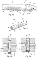
- FIG. 1a shows a wiper arm 10 according to the invention Wiper device. This has two ends, wherein on the one end 12 a wiper blade 13 is attached. At the other End 14 is the wiper arm 10 by means of a hinge pin 15 pivoted on a rotary head 16. At his, the Wiper arm 10 facing away from the rotary head 16 has a Receiving socket 18 for attachment to a not shown output shaft of the wiper device. At the one end 12 of the wiper arm 10 is the wiper blade 13 hinged, which rests on a wiping surface 20. is the wiper device installed in a motor vehicle, corresponds to the wiping surface of the windshield or Rear window of the vehicle.
- a Clamping element 22 attached at the other end 14 of the wiper arm 10 at the other end 14 of the wiper arm 10 . It consists of a tension spring 24th and a hook 26, each at the wiping surface 20 facing side of the wiper arm 10 and the rotary head sixteenth are hooked under bias. Due to the tension of the Clamping element 22, the wiper arm 10 is about his Hinge pin 15 with its one end 12 with the force F. pressed in the direction of the wiping surface 20.
- the eccentric pin 30 is detailed shown. This has essentially three cylindrical Sections on, with the two along its Longitudinal extension outer portions 32 a coaxial Central axis 34 have.
- the central axis of the middle Section 36 is from the coaxial center axis 34 different, in particular axis-parallel to the coaxial Central axis 34.
- the radius of the middle section 36 is always smaller or equal to the difference between the radius of the outer Sections 32 and the distance between the central axis coaxial 34 and the axis-parallel center axis 46, or otherwise
- the middle portion 36 is in cross section always within the circle of the outer sections 32 in the Preset cross section, since the eccentric pin 30 otherwise could not be introduced into the bore 42.
- the two outer sections 32 also have different radii.
- FIG. 3 shows a section through a rotary head 16 in FIG Area of the eccentric pin 30 shown.
- the middle section 36 in terms of his Longitudinal dimensioned so that the hook 26 of the Clamping element 22 hooked around the central portion 36 can be without the knurling 44 with the bore 42 in Intervention is.
- the contact force F be adjusted and at the end of the adjustment process of the Eccentric pin 30 is pressed into the bore and thus be locked so that a positive connection between bore 42 and knurling 44 the eccentric pin 30th secures before twisting. This is shown in FIG. 3b.
- the inventive method according to claim 11 can with an eccentric pin 30 shown in FIG be performed.
- the eccentric pin 30th partly along its longitudinal extent a knurling 44th as a security element.
- the eccentric pin 30 is in the hole 42 used, but only so far that the knurling 44 still not sunk in the bore 42.
- the middle section of the eccentric pin 30 is so wide that already this partial insertion is sufficient to hook 26 of the Clamp element 22 to hook the eccentric pin.
- eccentric pin 30 can in a variation of Invention, for example, a bolt can be used, the in the middle along its longitudinal extension has a sweeping screw. Is this with his side facing away from the head with the hook 26 in Engaging, can be used to adjust the head of the screw twisted and thus the spring preload be increased.
Landscapes
- Engineering & Computer Science (AREA)
- Mechanical Engineering (AREA)
- Pivots And Pivotal Connections (AREA)
- Connection Of Motors, Electrical Generators, Mechanical Devices, And The Like (AREA)
- Springs (AREA)
- Transmission Devices (AREA)
- Force Measurement Appropriate To Specific Purposes (AREA)
- Connection Of Plates (AREA)
Applications Claiming Priority (3)
| Application Number | Priority Date | Filing Date | Title |
|---|---|---|---|
| DE10051570A DE10051570A1 (de) | 2000-10-18 | 2000-10-18 | Wischvorrichtung und Verfahren zum Justieren der Auflagekraft eines Wischerarms |
| DE10051570 | 2000-10-18 | ||
| PCT/DE2001/003171 WO2002032730A1 (de) | 2000-10-18 | 2001-08-18 | Wischvorrichtung und verfahren zum justieren der auflagekraft eines wischerarms |
Publications (2)
| Publication Number | Publication Date |
|---|---|
| EP1335845A1 EP1335845A1 (de) | 2003-08-20 |
| EP1335845B1 true EP1335845B1 (de) | 2005-08-17 |
Family
ID=7660179
Family Applications (1)
| Application Number | Title | Priority Date | Filing Date |
|---|---|---|---|
| EP01964920A Expired - Lifetime EP1335845B1 (de) | 2000-10-18 | 2001-08-18 | Wischvorrichtung und verfahren zum justieren der auflagekraft eines wischerarms |
Country Status (12)
| Country | Link |
|---|---|
| US (1) | US6732399B2 (cs) |
| EP (1) | EP1335845B1 (cs) |
| JP (1) | JP2004510638A (cs) |
| KR (1) | KR100821497B1 (cs) |
| CN (1) | CN1211230C (cs) |
| AU (1) | AU2001285711A1 (cs) |
| BR (1) | BR0107331B1 (cs) |
| CZ (1) | CZ299588B6 (cs) |
| DE (3) | DE10051570A1 (cs) |
| ES (1) | ES2247160T3 (cs) |
| MX (1) | MXPA02006008A (cs) |
| WO (1) | WO2002032730A1 (cs) |
Families Citing this family (11)
| Publication number | Priority date | Publication date | Assignee | Title |
|---|---|---|---|---|
| DE102005030958A1 (de) * | 2005-06-30 | 2007-01-04 | Robert Bosch Gmbh | Wischerarm, insbesondere für eine Scheibenwischvorrichtung eines Kraftfahrzeugs |
| JP4749226B2 (ja) * | 2006-05-09 | 2011-08-17 | 株式会社豊田自動織機 | ワイパ構造 |
| US20080155777A1 (en) * | 2006-12-31 | 2008-07-03 | Honda R&D Americas, Inc. | Windshield wiper with adjustable bearing force |
| CN102837674B (zh) * | 2012-08-28 | 2014-12-24 | 天津博信汽车零部件有限公司 | 雨刮器 |
| CN203237216U (zh) * | 2013-01-06 | 2013-10-16 | 博世汽车部件(长沙)有限公司 | 连接钩及刮水器 |
| DE102014221424A1 (de) * | 2014-10-22 | 2016-04-28 | Robert Bosch Gmbh | Verstellmechanismus für eine Wischeranlage sowie Wischeranlage |
| CN105799649A (zh) * | 2016-05-26 | 2016-07-27 | 刘晓静 | 雨刮装置 |
| CN109655252B (zh) * | 2019-02-18 | 2024-01-26 | 上汽大众汽车有限公司 | 拆装雨刮弹簧的凸轮连杆机构 |
| CN111252036B (zh) * | 2020-02-13 | 2021-12-31 | 上汽大众汽车有限公司 | 一种雨刮刮杆压力调节装置、雨刮刮杆及车辆 |
| DE102020110430A1 (de) | 2020-04-16 | 2021-10-21 | Endress+Hauser Conducta Gmbh+Co. Kg | Sensor mit einer Reinigungsvorrichtung |
| CN112697696B (zh) * | 2020-12-09 | 2023-08-15 | 贵阳万江航空机电有限公司 | 一种雨刮片与玻璃摩擦力测试仪及其测试方法 |
Family Cites Families (13)
| Publication number | Priority date | Publication date | Assignee | Title |
|---|---|---|---|---|
| US2289552A (en) * | 1940-05-27 | 1942-07-14 | Trico Products Corp | Windshield wiper arm |
| US3366989A (en) * | 1965-10-22 | 1968-02-06 | Hastings Mfg Co | Windshield wiper arms |
| JPS5889441A (ja) * | 1981-11-24 | 1983-05-27 | Jidosha Denki Kogyo Co Ltd | ワイパ装置 |
| GB2215148B (en) | 1988-02-18 | 1992-04-08 | Fenner Co Ltd J H | A monitoring system |
| JP2762597B2 (ja) * | 1989-08-10 | 1998-06-04 | 日産自動車株式会社 | ワイパー装置 |
| DE4033201A1 (de) * | 1990-10-19 | 1992-04-23 | Swf Auto Electric Gmbh | Scheibenwischeranlage, insbesondere fuer kraftfahrzeuge |
| US5369740A (en) | 1991-09-12 | 1994-11-29 | Emerson Electric Co. | Versatile programmable electronic controller |
| JP3295425B2 (ja) * | 1991-11-11 | 2002-06-24 | アイティーティー・オートモーティブ・ヨーロップ・ゲーエムベーハー | 自動車のフロントガラスを洗浄するためのワイパーアーム |
| JPH05139255A (ja) * | 1991-11-18 | 1993-06-08 | Asmo Co Ltd | ワイパー装置 |
| FR2720708B1 (fr) * | 1994-06-07 | 1996-07-05 | Journee Paul Sa | Essuie-glace comportant des moyens pour régler la valeur nominale du couple d'essuyage. |
| FR2724896B1 (fr) * | 1994-09-23 | 1996-12-13 | Valeo Systemes Dessuyage | Ressort de tarage de la force d'essuyage d'un essuie-glace |
| IT1298550B1 (it) | 1998-02-04 | 2000-01-12 | Whirlpool Co | Dispositivo di controllo di un elettrodomestico con memoria non volatile facilmente riprogrammabile dall'esterno |
| SE520096C2 (sv) | 1998-12-10 | 2003-05-27 | Atlas Copco Tools Ab | System för kraftverktyg innefattande till- och frånkopplingsbar minnesmodul för lagring och överföring av data mellan olika enheter |
-
2000
- 2000-10-18 DE DE10051570A patent/DE10051570A1/de not_active Withdrawn
-
2001
- 2001-08-18 JP JP2002535932A patent/JP2004510638A/ja not_active Withdrawn
- 2001-08-18 DE DE10194406T patent/DE10194406D2/de not_active Expired - Lifetime
- 2001-08-18 BR BRPI0107331-1A patent/BR0107331B1/pt not_active IP Right Cessation
- 2001-08-18 ES ES01964920T patent/ES2247160T3/es not_active Expired - Lifetime
- 2001-08-18 US US10/089,619 patent/US6732399B2/en not_active Expired - Fee Related
- 2001-08-18 WO PCT/DE2001/003171 patent/WO2002032730A1/de not_active Ceased
- 2001-08-18 EP EP01964920A patent/EP1335845B1/de not_active Expired - Lifetime
- 2001-08-18 DE DE50107152T patent/DE50107152D1/de not_active Expired - Lifetime
- 2001-08-18 MX MXPA02006008A patent/MXPA02006008A/es active IP Right Grant
- 2001-08-18 CZ CZ20021909A patent/CZ299588B6/cs not_active IP Right Cessation
- 2001-08-18 CN CNB018031862A patent/CN1211230C/zh not_active Expired - Fee Related
- 2001-08-18 AU AU2001285711A patent/AU2001285711A1/en not_active Abandoned
- 2001-08-18 KR KR1020027007728A patent/KR100821497B1/ko not_active Expired - Fee Related
Also Published As
| Publication number | Publication date |
|---|---|
| JP2004510638A (ja) | 2004-04-08 |
| BR0107331A (pt) | 2002-08-27 |
| WO2002032730A1 (de) | 2002-04-25 |
| KR100821497B1 (ko) | 2008-04-11 |
| CN1394179A (zh) | 2003-01-29 |
| DE50107152D1 (de) | 2005-09-22 |
| MXPA02006008A (es) | 2003-03-27 |
| US6732399B2 (en) | 2004-05-11 |
| KR20020065577A (ko) | 2002-08-13 |
| DE10194406D2 (de) | 2003-09-11 |
| CN1211230C (zh) | 2005-07-20 |
| BR0107331B1 (pt) | 2009-08-11 |
| DE10051570A1 (de) | 2002-04-25 |
| EP1335845A1 (de) | 2003-08-20 |
| CZ299588B6 (cs) | 2008-09-10 |
| AU2001285711A1 (en) | 2002-04-29 |
| CZ20021909A3 (cs) | 2002-10-16 |
| US20020133898A1 (en) | 2002-09-26 |
| ES2247160T3 (es) | 2006-03-01 |
Similar Documents
| Publication | Publication Date | Title |
|---|---|---|
| DE19634343C2 (de) | Spanneinrichtung für Zugmittel mit festgelegtem Spannweg | |
| EP1426636B1 (de) | Schnellmontagemutter | |
| DE29724656U1 (de) | Befestigungsvorrichtung | |
| DE69510783T2 (de) | Schnellwechselsägeblattspannvorrichtung, bedienbar ohne zusätzliches werkzeug, für hin- und hergehende sägen | |
| DE2405262A1 (de) | Spannschraube | |
| EP0299147B1 (de) | Türfeststeller, insbesondere für Kraftwagentüren | |
| WO2002032730A1 (de) | Wischvorrichtung und verfahren zum justieren der auflagekraft eines wischerarms | |
| DE19839527A1 (de) | Lenksäule für ein Kraftfahrzeug | |
| DE19681309C2 (de) | Wischervorrichtung | |
| DE19929914A1 (de) | Wischarm | |
| DE4036367C2 (de) | Scheibenwischerantriebseinrichtung für Kraftfahrzeuge | |
| DE3509831A1 (de) | Scheinwerfer fuer kraftfahrzeuge | |
| DE29713995U1 (de) | Türscharnier mit Feststeller | |
| DE69105691T2 (de) | Scheibenwischerarm besonders für Kraftfahrzeuge. | |
| EP1270350A2 (de) | Justiereinrichtung und zugehöriges Betätigungswerkzeug | |
| EP1541896A1 (de) | Riemen-Spannvorrichtung | |
| DE102012204810B3 (de) | Sicherheitsgurteinrichtung mit einem Endbeschlagstraffer | |
| EP1007860B1 (de) | Lagerelement für verstelleinrichtungen in kraftfahrzeugen | |
| DE8915002U1 (de) | Halbautomatisches Spannorgan für einen Riementrieb | |
| DE3423106A1 (de) | Abstandhalter fuer elektrische leiter, insbesondere fuer blitzschutzleiter | |
| DE10109660B4 (de) | Sicherungsring und Befestigungsvorrichtung für eine Welle-Nabe-Verbindung | |
| EP1163083B1 (de) | Winkelschleifer | |
| DE4033216C2 (de) | Schwenklagerverbindung für eine Antriebsvorrichtung, insbesondere für eine Hubwischeranlage für Kraftfahrzeuge | |
| DE102005046325B4 (de) | Vorrichtung zum Befestigen einer Wischerfunktionseinheit an einer Wischerwelle | |
| EP0259540B1 (de) | Türfeststeller, insbesondere für Kraftwagentüren |
Legal Events
| Date | Code | Title | Description |
|---|---|---|---|
| PUAI | Public reference made under article 153(3) epc to a published international application that has entered the european phase |
Free format text: ORIGINAL CODE: 0009012 |
|
| 17P | Request for examination filed |
Effective date: 20030519 |
|
| AK | Designated contracting states |
Designated state(s): DE ES FR GB IT |
|
| AX | Request for extension of the european patent |
Extension state: AL LT LV MK RO SI |
|
| 17Q | First examination report despatched |
Effective date: 20040716 |
|
| GRAP | Despatch of communication of intention to grant a patent |
Free format text: ORIGINAL CODE: EPIDOSNIGR1 |
|
| GRAS | Grant fee paid |
Free format text: ORIGINAL CODE: EPIDOSNIGR3 |
|
| GRAA | (expected) grant |
Free format text: ORIGINAL CODE: 0009210 |
|
| AK | Designated contracting states |
Kind code of ref document: B1 Designated state(s): DE ES FR GB IT |
|
| REG | Reference to a national code |
Ref country code: GB Ref legal event code: FG4D Free format text: NOT ENGLISH |
|
| REF | Corresponds to: |
Ref document number: 50107152 Country of ref document: DE Date of ref document: 20050922 Kind code of ref document: P |
|
| GBT | Gb: translation of ep patent filed (gb section 77(6)(a)/1977) |
Effective date: 20051102 |
|
| REG | Reference to a national code |
Ref country code: ES Ref legal event code: FG2A Ref document number: 2247160 Country of ref document: ES Kind code of ref document: T3 |
|
| ET | Fr: translation filed | ||
| PLBE | No opposition filed within time limit |
Free format text: ORIGINAL CODE: 0009261 |
|
| STAA | Information on the status of an ep patent application or granted ep patent |
Free format text: STATUS: NO OPPOSITION FILED WITHIN TIME LIMIT |
|
| 26N | No opposition filed |
Effective date: 20060518 |
|
| PGFP | Annual fee paid to national office [announced via postgrant information from national office to epo] |
Ref country code: ES Payment date: 20100830 Year of fee payment: 10 |
|
| PGFP | Annual fee paid to national office [announced via postgrant information from national office to epo] |
Ref country code: IT Payment date: 20100825 Year of fee payment: 10 |
|
| PGFP | Annual fee paid to national office [announced via postgrant information from national office to epo] |
Ref country code: GB Payment date: 20100823 Year of fee payment: 10 |
|
| GBPC | Gb: european patent ceased through non-payment of renewal fee |
Effective date: 20110818 |
|
| PG25 | Lapsed in a contracting state [announced via postgrant information from national office to epo] |
Ref country code: IT Free format text: LAPSE BECAUSE OF NON-PAYMENT OF DUE FEES Effective date: 20110818 |
|
| PG25 | Lapsed in a contracting state [announced via postgrant information from national office to epo] |
Ref country code: GB Free format text: LAPSE BECAUSE OF NON-PAYMENT OF DUE FEES Effective date: 20110818 |
|
| REG | Reference to a national code |
Ref country code: ES Ref legal event code: FD2A Effective date: 20130531 |
|
| PG25 | Lapsed in a contracting state [announced via postgrant information from national office to epo] |
Ref country code: ES Free format text: LAPSE BECAUSE OF NON-PAYMENT OF DUE FEES Effective date: 20110819 |
|
| PGFP | Annual fee paid to national office [announced via postgrant information from national office to epo] |
Ref country code: DE Payment date: 20141024 Year of fee payment: 14 |
|
| REG | Reference to a national code |
Ref country code: FR Ref legal event code: PLFP Year of fee payment: 15 |
|
| PGFP | Annual fee paid to national office [announced via postgrant information from national office to epo] |
Ref country code: FR Payment date: 20150824 Year of fee payment: 15 |
|
| REG | Reference to a national code |
Ref country code: DE Ref legal event code: R119 Ref document number: 50107152 Country of ref document: DE |
|
| PG25 | Lapsed in a contracting state [announced via postgrant information from national office to epo] |
Ref country code: DE Free format text: LAPSE BECAUSE OF NON-PAYMENT OF DUE FEES Effective date: 20160301 |
|
| REG | Reference to a national code |
Ref country code: FR Ref legal event code: ST Effective date: 20170428 |
|
| PG25 | Lapsed in a contracting state [announced via postgrant information from national office to epo] |
Ref country code: FR Free format text: LAPSE BECAUSE OF NON-PAYMENT OF DUE FEES Effective date: 20160831 |