EP1335632A2 - Befestigungseinrichtung für elektrische Heizeinrichtungen - Google Patents
Befestigungseinrichtung für elektrische Heizeinrichtungen Download PDFInfo
- Publication number
- EP1335632A2 EP1335632A2 EP03002771A EP03002771A EP1335632A2 EP 1335632 A2 EP1335632 A2 EP 1335632A2 EP 03002771 A EP03002771 A EP 03002771A EP 03002771 A EP03002771 A EP 03002771A EP 1335632 A2 EP1335632 A2 EP 1335632A2
- Authority
- EP
- European Patent Office
- Prior art keywords
- fastening
- mounting bracket
- heating device
- fastening device
- heating
- Prior art date
- Legal status (The legal status is an assumption and is not a legal conclusion. Google has not performed a legal analysis and makes no representation as to the accuracy of the status listed.)
- Withdrawn
Links
Images


Classifications
-
- H—ELECTRICITY
- H05—ELECTRIC TECHNIQUES NOT OTHERWISE PROVIDED FOR
- H05B—ELECTRIC HEATING; ELECTRIC LIGHT SOURCES NOT OTHERWISE PROVIDED FOR; CIRCUIT ARRANGEMENTS FOR ELECTRIC LIGHT SOURCES, IN GENERAL
- H05B6/00—Heating by electric, magnetic or electromagnetic fields
- H05B6/02—Induction heating
- H05B6/10—Induction heating apparatus, other than furnaces, for specific applications
- H05B6/12—Cooking devices
- H05B6/1209—Cooking devices induction cooking plates or the like and devices to be used in combination with them
- H05B6/1245—Cooking devices induction cooking plates or the like and devices to be used in combination with them with special coil arrangements
- H05B6/1254—Cooking devices induction cooking plates or the like and devices to be used in combination with them with special coil arrangements using conductive pieces to direct the induced magnetic field
-
- F—MECHANICAL ENGINEERING; LIGHTING; HEATING; WEAPONS; BLASTING
- F24—HEATING; RANGES; VENTILATING
- F24C—DOMESTIC STOVES OR RANGES ; DETAILS OF DOMESTIC STOVES OR RANGES, OF GENERAL APPLICATION
- F24C15/00—Details
- F24C15/10—Tops, e.g. hot plates; Rings
- F24C15/102—Tops, e.g. hot plates; Rings electrically heated
-
- H—ELECTRICITY
- H05—ELECTRIC TECHNIQUES NOT OTHERWISE PROVIDED FOR
- H05B—ELECTRIC HEATING; ELECTRIC LIGHT SOURCES NOT OTHERWISE PROVIDED FOR; CIRCUIT ARRANGEMENTS FOR ELECTRIC LIGHT SOURCES, IN GENERAL
- H05B2206/00—Aspects relating to heating by electric, magnetic, or electromagnetic fields covered by group H05B6/00
- H05B2206/02—Induction heating
- H05B2206/022—Special supports for the induction coils
-
- Y—GENERAL TAGGING OF NEW TECHNOLOGICAL DEVELOPMENTS; GENERAL TAGGING OF CROSS-SECTIONAL TECHNOLOGIES SPANNING OVER SEVERAL SECTIONS OF THE IPC; TECHNICAL SUBJECTS COVERED BY FORMER USPC CROSS-REFERENCE ART COLLECTIONS [XRACs] AND DIGESTS
- Y02—TECHNOLOGIES OR APPLICATIONS FOR MITIGATION OR ADAPTATION AGAINST CLIMATE CHANGE
- Y02B—CLIMATE CHANGE MITIGATION TECHNOLOGIES RELATED TO BUILDINGS, e.g. HOUSING, HOUSE APPLIANCES OR RELATED END-USER APPLICATIONS
- Y02B40/00—Technologies aiming at improving the efficiency of home appliances, e.g. induction cooking or efficient technologies for refrigerators, freezers or dish washers
Definitions
- the invention relates to a fastening device for electrical heating devices according to the preamble of claim 1.
- the heaters are flat induction heaters, for example are arranged under a hob.
- the invention has for its object a fastening device mentioned to create, on the one hand, the attachment of Heating devices on a mounting bracket simple and on the other hand with desired accuracy is possible.
- the fastening device has fastening means on.
- a mounting bracket is also provided.
- the fastening device can have the mounting bracket.
- the fasteners are designed such that the Attachment of the heater to the mounting bracket with respect to Position is variable, this being based on the position of the heater relates to the mounting bracket. This can be advantageous through the Using the center of gravity of the heating device clarifies become.
- marking means can be provided be with which different positions of attachment of the Heating device can be marked on the mounting bracket.
- marking means can be provided be with which different positions of attachment of the Heating device can be marked on the mounting bracket.
- a fastening device according to the invention possible positions for different types of hobs to be marked on a mounting bracket.
- Other methods, such as special templates can then be omitted. So can both an initial attachment of a heater to the mounting bracket as well as the formation of variants by dismantling the Heating device and reattaching can be done very easily. It takes only the mark associated with a desired position is known to be, in order to then fix the heating device accordingly. This means that aids can largely be dispensed with.
- the fastening device serve one or more heating devices under a cover, for example, a glass ceramic hob.
- the marking means can at least partially, in particular for the most part, be formed on the mounting bracket. This can be done by printing or sticking on markings. You can also Markings can also be punched out or embossed. Advantageous a part or area of a heating device can be designed in such a way that it works functionally with the marking agents.
- the marking means in an area between the heating device and the mounting bracket be arranged.
- the position or definition of a Heating device on the mounting bracket by determining one of several markings of the marking means, which a specific one Indicates position by applying an outer edge or characteristic Point of the heating device.
- a part of the heating device can be equipped with the marking means interact.
- aligning the heating device by means of the marking means also by a corresponding one Marking or the like on the heating device. It can a heater with its edge along a scale up to one certain point on the scale.
- the marking means can be carried out in a variety of ways his. They are preferably essentially running in one piece or intended for a minimum of two heaters educated. In this way, markers can be more versatile be used.
- Marking means can be designed, for example, with a scale his. This scale can essentially be linear scaling or have a graduation with fixed and equal distances.
- the marking means can be essentially one have a continuous course, for example arcuate or advantageously straightforward.
- An exemplary implementation of such marking means can be a kind of ruler with millimeter scaling, for example applied to a flat mounting bracket, be formed.
- the fastening means can preferably be simple, in particular without tools, attached and / or detached. Thus both a heater can be installed quickly. Furthermore, it is possible, pre-assembled heating devices to form variants to loosen and attach to a desired other position. It is advantageous here if the fastening means can be released repeatedly and are attachable. A screw connection is particularly preferred here.
- the fastening means can have at least one fastening screw have, which on the heating device and the Mounting bracket attacks. You can in particular in an opening or a Engage threads in the mounting bracket.
- the screw can either the heating device or on the mounting bracket in a longitudinal slot run to adjust the position.
- a longitudinal slot can straight or advantageously be arched.
- the longitudinal slot can on the mounting bracket, on the heater or the Fasteners or be provided on both.
- a two-point fastening a heating device on the one hand a fastening element, such as a hook.
- the second attachment point can then be made using a screw.
- fasteners can be flat as well as being tool-free.
- Those are also particularly advantageous Fasteners designed to be used repeatedly.
- a mounting bracket can be designed in many different ways. In one embodiment of the invention, it can be attached to a cover be trained. Such a cover can be a glass ceramic field or the like for a hob.
- the mounting bracket can be a Define area which is adapted to the area of this cover is, in particular is approximately the same shape.
- the mounting bracket can on the one hand, a frame that is connected to the cover.
- the mounting bracket can be a base plate or a housing his. Such a housing can then be used for all heating devices, possibly also an associated control, for example for a Record the hob.
- the mounting bracket can consist of several parts his. He can have a main mounting bracket as well as at least have one, preferably several, sub-assembly supports. This can be provided for special types of heating devices for which it It is advantageous if the heating device by means of such a sub-mounting bracket is attached.
- sub-mounting bracket it is possible to mount the sub-mounting bracket to train a heating device. This will be described later.
- sub-assembly beams as brackets, which overlap a heating device. At least part of the markers can be provided on a sub-mounting bracket to align the heater with the main mounting bracket.
- the sub-assembly beams can be with their ends or an outer edge be attachable to the main mounting bracket, preferably positively or with a screw connection.
- the heating device can be attached to the mounting bracket on the one hand be rigid. On the other hand, it can be fixed laterally, but height-adjustable his.
- the height adjustment can in particular be done independently be carried out, for example by means of a spring device. This means that the heating device projects upwards in a spring-elastic manner and, for example, when using a cover permanently with a Predefinable spring force is applied to this.
- the heating device with at least one stable one
- an outer frame can, especially in the case of induction heating, advantageously Be plastic.
- it can serve as a kind of plate be trained and accommodate the heating device.
- a fastening device for Flat electrical heating devices in the case of induction heating have a receiving plate as a heating device.
- a Induction heating is advantageous with a flat, round induction coil provided and arranged in such a receiving plate.
- a mounting plate can be part of the mounting bracket and / or the fastener. In particular, fastening screws or flat fasteners on the receiving plate attack and interact with the mounting bracket.
- a mounting plate can be specially designed for induction heating his.
- it can have, for example, shapes in which Parts of the induction coil, for example ferrite cores, are positioned and / or can be attached.
- Parts of the induction coil for example ferrite cores
- a mounting plate possibly also an assembly bracket, a cable guide for the connection cables of the induction heating exhibit.
- a cable routing can either be carried out the cable through the receiving plate or the mounting bracket essentially be trained in one place.
- a cable guide be designed as an elongated cable duct.
- a carrier 11a is shown, which on a mounting bracket, such as it emerges, for example, from FIGS. 3 to 5, can be fastened.
- the carrier 11a is essentially a circular plate and has as a fastener both a clamp hook 12a and one Longitudinal slot 16 in an approach 15a.
- the carrier 11a can be made of sheet metal or stable plastic.
- a flat and round induction coil can be applied become.
- the induction coil can then be carried out by means of the carrier 11a to be assembled. This has the advantage that, as for the structure in Fig.5 Explained later, the induction coil is a pre-made and stable as well as easy to handle assembly.
- a scale 19a is attached along the arcuate longitudinal slot 16a.
- This scale 19a can be attached in various ways be, for example by punching, embossing, printing or Spraying. As can be seen, there are different positions on the Marked 19a. Similar to scaling a curve ruler or of a protractor are marks with the same distance from each other intended. They are numbered in five steps. The markings can either correspond to an angular measure or others Data, for example measured in millimeters. Alternatively, you can predetermined positions are marked, which are not necessarily in must be the same distance from each other.
- the longitudinal slot 16a does not necessarily have to be arcuate. It offers however, attach it to the outer contour of the wearer 11a to train.
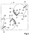
- the carrier 11a can be in a longitudinal slot or the like on a mounting bracket 17, as shown in Fig.3 emerges, are attached.
- the clamping hook 12a is a side view shown. It consists of one by cuts of that remaining carrier 11 a separated arm 13 and one of its end T-shaped outgoing end piece 14.
- the arm 13 has a width slightly less than the width of an associated longitudinal slot 16.
- the end piece 14 is so far below the underside of the carrier 11a that it is in coordination with the angle of the arm 13 slanted support 11a so far through the mounting bracket 17th is enough that a free movement is guaranteed.
- FIG. 3 shows slightly modified designs of carriers 11b, the on a rectangular and plate-shaped mounting bracket 17th are attached.
- the lugs 15b with the Longitudinal slots 16b and the clamping hooks 12b are formed as separate parts and attached to the brackets 11b.
- Such an attachment can be screwed, riveted, welded or glued getting produced. Screwing is preferred.
- the screw hole line 20 runs straight and has a number of screw holes. So it essentially corresponds one of the longitudinal slots 18, but with discrete positions.
- Scales 19 are present along the longitudinal slots 18. You can similar to how the scale 19a are made, see above Description.
- the screw hole line 20 is a pure number scale 19c assigned. The individual screw holes are numbered consecutively.
- the carrier 11b In the case of the carrier 11b, this can be done at the top right such that the Carrier on one side along one of the scales 19b on one of the two Longitudinal slots 18 is positioned.
- the scale can be the outer edge of the carrier 11b or the arm 13 a clamping hook 12b in the area of the passage through the mounting bracket 17 can be used with respect to the scale 19b.
- the second Part of the step is that one through the longitudinal slot 16b gripping fastening screw 21 on the scale 19b of the projection 15b is moved along and fixed. Once this has been done, the position of the Carrier 11b and thus also the induction coil relative to the mounting bracket 17 clearly defined. By tightening the fastening screw 21, the bracket 11b is finally secured in position on the mounting bracket 17.
- the screwing is also in a continuous longitudinal slot 18 possible, for example with a self-tapping screw.
- 17 cable guides 23b are provided in the mounting bracket. These consist of punched and issued clamps, like a hook over the top or bottom of the Survive mounting bracket 17. A connection cable can be placed in these hooks be inserted or clamped for induction heating. In this manner way the cables can be laid and fastened in a clean and defined manner become.
- FIG. 4 shows, on the one hand, alternative designs of carriers 11c. These differ from the previous ones in that that the lugs 15c only a single hole instead of a longitudinal slot exhibit.
- the clamp hooks 12b correspond to the clamp hook from Fig. 3.
- Scales 19b are again along the longitudinal slots 18 similar to Fig.3 provided.
- the screw hole fields 26 are provided with scales 19d, which essentially in the manner of a coordinate system, for example can be provided with numbers and letters. So can by specifying the two coordinates exactly one screw hole of the Determines screw hole field 26 and the fastening screw 21 therein be screwed in. While thus two fasteners in Fig.3 per beam with line shape or line character in the mounting beam 17 are provided, there are all adjustment options in the embodiment according to FIG in the mounting bracket 17 includes.
- the carrier 11c is only with two point fasteners, namely the Clamping hooks 12b and 15c with a single screw hole, stocked.
- a longitudinal slot 18 and a screw hole line 20 The difference between a longitudinal slot 18 and a screw hole line 20 is that with a longitudinal slot 18 a stepless adjustment is possible. With a screw hole line 20, or even one Screw hole field 26 is only an adjustment with discrete steps possible. In most cases, however, this is considered sufficient since an adjustment of the carrier 11 or the one located thereon Induction coils are not necessarily accurate to the millimeter in some applications must be done.
- FIG. 5 shows a structure of an induction heating device 27 according to another aspect of the present and previously described Invention shown.
- the induction device 27 is in a receiving plate 28 according to the invention housed or therein built up.
- the receiving plate 28 is formed as an integral part, namely either punched out of metal or deep drawn from plastic, for example. It has an outer edge 30 which is pulled downwards. This way there will be a gap down as well as an improvement of stability achieved. At a point on the left front there is a clamp hook 12d downwards. A projection 15d is present diametrically opposite with a hole for passing a fastening screw.
- the receiving plate 28 instructs radially offset inwards its top has a circumferentially extending boundary 31 on. This forms an alignment or assembly aid for the components the induction heating device 27. On the other hand, in particular with a continuous boundary 31 as shown here, the Components of the induction heating device completely enclosed become. Furthermore, 28 are star-shaped in the receiving plate Wells 33 formed. A recess 34 is provided in the center.
- the recesses 33 are to be dimensioned accordingly.
- the recesses can have slightly curved walls exhibit. This makes it possible to clamp the ferrites.
- the coil former 37 is in the boundary 31 inserted.
- the coil former 37 is designed in the form of an annular disk. This is achieved by winding the coil 37 accordingly.
- Schematic connection cables 38 of the coil former 37 are shown go from an inner area and are through the recess 34 performed in the receiving plate 28. For example, these connection cables 38 through the cable guides 23c and a hole 24c in the Mounting bracket 17 are guided downwards according to FIG. Likewise it is possible that they are in the cavity below the receiving plate 28, which is formed by the outer edge 30 drawn downwards, be led outside.
- a disc-shaped, flat insulation 40 This is also placed within the boundary 31. It covers the induction heating device 27 from above and isolates it for example against a glass ceramic plate that is set up by a hot pot is heated.
- the top of the insulation 40 carries an exemplary illustrated flat temperature sensor 41. This is used to record the temperature on the top of the insulation 40 or one running above it Glass ceramic plate and is known per se from the prior art.
- the temperature sensor 41 in turn has a temperature sensor cable 42 on that through the generally soft insulation 40, the inner recess in the bobbin 37 and the recess 34 in the receiving plate 28 is performed.
- the coil former 37 is a stable and manageable in itself Unit.
- the coil can already be cast into it or be glued.
- the induction heater is on 27 fully assembled. It can be provided that the ferrites 36, the coil former 37 or the insulation 40 with one another or be glued to the receiving plate 28. Alternatively, one Covering, for example with an adhesive film or the like, at least of the receiving plate 28 and the insulation 40 take place. To this way, a structural unit that is stable in itself and very easy to handle, namely that of an induction heating device.
- the mounting bracket 17 can be seen laterally be provided with raised outer edges.
- the induction heaters are like one Housing housed.
- An above-mentioned resilient pressure on a cover can, for example, with an induction heating device 27 according to FIG strong elastic insulation 40 against such a cover can be pressed. Furthermore, between the Recording plate 28 and the bobbin 37 a highly resilient Layer or a large, flat spring can be arranged, and push it up.
- scales 19 are only on the Mounting bracket 17 and not provided on the bracket 11. Alignment takes place by taking measurements with the edge of the carrier 11c the scale.
Landscapes
- Engineering & Computer Science (AREA)
- Physics & Mathematics (AREA)
- Electromagnetism (AREA)
- Chemical & Material Sciences (AREA)
- Combustion & Propulsion (AREA)
- Mechanical Engineering (AREA)
- General Engineering & Computer Science (AREA)
- General Induction Heating (AREA)
Abstract
Description
- Fig.1
- eine Draufsicht auf einen Träger für eine Induktionsspule mit einem Befestigungshaken an einer Seite und einem Längsschlitz an der anderen,
- Fig.2
- eine Seitenansicht des Befestigungshakens aus Fig.1,
- Fig.3/4
- Draufsichten auf flächige Montageträger mit Längsschlitzen verschiedener Art sowie Linien oder Feldern von Schraublöchern und
- Fig.5
- eine Explosionsdarstellung des Aufbaus einer Induktionsspule mit einem speziell ausgebildeten Aufnahmeteller.
Claims (20)
- Befestigungsvorrichtung für insbesondere flächige elektrische Heizeinrichtungen (27), gekennzeichnet durch:Befestigungsmittel (12, 21) zur Befestigung der Heizeinrichtung (27) an einem Montageträger (17),die Befestigungsmittel (12, 21) sind ausgebildet derart, dass die Befestigung der Heizeinrichtung (27) an dem Montageträger (17) von der Position her variabel ist.
- Befestigungsvorrichtung nach Anspruch 1, dadurch gekennzeichnet, dass die Befestigungsvorrichtung den Montageträger (17) aufweist.
- Befestigungsvorrichtung nach Anspruch 1 oder 2, dadurch gekennzeichnet, dass die Heizeinrichtung (27) mittels der Befestigungsvorrichtung unter einer Abdeckung, wie beispielsweise einem Glaskeramikkochfeld, anbringbar ist.
- Befestigungsvorrichtung nach einem der vorhergehenden Ansprüche, gekennzeichnet durch Markierungsmittel (19) zur Markierung verschiedener Positionen der Befestigung zwischen Heizeinrichtung (27) und Montageträger (17).
- Befestigungsvorrichtung nach Anspruch 4, dadurch gekennzeichnet, dass die Markierungsmittel (19) zumindest teilweise, insbesondere größtenteils, an dem Montageträger (17) ausgebildet sind, wobei vorzugsweise ein Bereich der Heizeinrichtung (27) zur Zusammenwirkung mit den Markierungsmitteln ausgebildet ist.
- Befestigungsvorrichtung nach Anspruch 4 oder 5, dadurch gekennzeichnet, dass die Markierungsmittel (19) einen im wesentlichen kontinuierlichen Verlauf aufweisen, insbesondere geradlinig sind, wobei sie vorzugsweise am Stück und/oder in einem Bereich für mindestens zwei Heizeinrichtungen (27) ausgebildet sind.
- Befestigungsvorrichtung nach einem der Ansprüche 4 bis 6, dadurch gekennzeichnet, dass die Markierungsmittel (19) eine Skala aufweisen, insbesondere mit im wesentlichen linearer Skalierung und/oder mit einer Skaleneinteilung mit festen und gleichen Abständen.
- Befestigungsvorrichtung nach einem der Ansprüche 4 bis 7, dadurch gekennzeichnet, dass die Markierungsmittel (19) in einem Bereich zwischen Heizungseinrichtung (27) und Montageträger (17) angeordnet sind derart, dass die Position bzw. Festlegung einer Heizungseinrichtung an dem Montageträger mittels Bestimmen einer von mehreren Markierungen der Markierungsmittel durch Anliegen eines Außenrandes (30) der Heizungseinrichtung daran erfolgt.
- Befestigungsvorrichtung nach einem der vorhergehenden Ansprüche, dadurch gekennzeichnet, dass die Befestigungsmittel (12, 21) einfach lösbar sind, vorzugsweise wiederholt lösbar und befestigbar, wobei insbesondere die Befestigungsmittel wenigstens eine Befestigungsschraube (21) aufweisen, die an der Heizungseinrichtung (27) angeordnet ist und in den Montageträger (17) eingreift, wobei sie vorzugsweise in eine Öffnung (18, 20, 26) eingreift.
- Befestigungsvorrichtung nach Anspruch 9, dadurch gekennzeichnet, dass die Zuordnung einer Befestigungsschraube (21) zu der Heizungseinrichtung (27) mittels der Befestigungsmittel in einem bestimmten Bereich verstellbar ist, insbesondere entlang eines Längsschlitzes (18), wobei vorzugsweise ein Längsschlitz bogenförmig ist.
- Befestigungsvorrichtung nach Anspruch 9, dadurch gekennzeichnet, dass die Befestigungsmittel flächig und werkzeuglos lösbar sind, vorzugsweise wiederholt verwendbar ausgebildet sind, wobei sie insbesondere als textiler Haftverschluss oder dergleichen ausgebildet sind.
- Befestigungsvorrichtung nach einem der vorhergehenden Ansprüche, dadurch gekennzeichnet, dass die Befestigungsmittel (12, 21) mindestens zwei Punkte aufweisen zur definierten Befestigung der Heizungseinrichtung (27) an dem Montageträger (17), wobei vorzugsweise die Befestigung an beiden Punkten in einem bestimmten Bereich verstellbar ist und insbesondere die Befestigungsmittel an einem Punkt eine Verschraubung (21) und an einem anderen Punkt einen Befestigungs- oder Klemmhaken (12) aufweisen.
- Befestigungsvorrichtung nach einem der vorhergehenden Ansprüche, dadurch gekennzeichnet, dass der Montageträger (17) zur Befestigung an einer Abdeckung ausgebildet ist und insbesondere eine der Fläche dieser Abdeckung angepasste Fläche definiert, vorzugsweise entsprechend als Rahmen oder Grundplatte.
- Befestigungsvorrichtung nach einem der vorhergehenden Ansprüche, dadurch gekennzeichnet, dass der Montageträger mehrteilig ist und einen Haupt-Montageträger (17) sowie mindestens einen Unter-Montageträger (11) aufweist, wobei mindestens eine Heizeinrichtung (27) mittels eines Unter-Montageträgers an dem Haupt-Montageträger befestigbar ist, wobei vorzugsweise vier Heizeinrichtungen mittels mehrerer Unter-Montageträger an einem Haupt-Montageträger befestigbar sind.
- Befestigungsvorrichtung nach Anspruch 14, dadurch gekennzeichnet, dass die Unter-Montageträger als Bügel zum Übergreifen einer Heizeinrichtung ausgebildet sind, wobei vorzugsweise Markierungsmittel an dem Unter-Montageträger vorgesehen sind und insbesondere die Unter-Montageträger mit ihren Enden an dem Haupt-Montageträger befestigbar sind.
- Befestigungsvorrichtung nach einem der vorhergehenden Ansprüche, dadurch gekennzeichnet, dass die Heizeinrichtung (27) höhenverstellbar an dem Montageträger (17) befestigbar ist, wobei sie vorzugsweise selbständig höhenverstellbar ist, insbesondere mittels einer Federeinrichtung.
- Befestigungsvorrichtung nach einem der vorhergehenden Ansprüche, dadurch gekennzeichnet, dass die Heizeinrichtung (27) zumindest einen stabilen Außenrahmen oder dergleichen aufweist, insbesondere aus Kunststoff, wobei der Außenrahmen vorzugsweise als Teller (28) ausgebildet ist.
- Befestigungsvorrichtung für flächige elektrische Heizeinrichtungen, insbesondere nach Anspruch 17, dadurch gekennzeichnet, dass eine Heizeinrichtung (27) eine Induktionsheizung ist mit einer flachen, runden Induktionsspule (37), wobei die Induktionsheizung in einem Aufnahmeteller (28) angeordnet ist und vorzugsweise der Aufnahmeteller Teil eines Montageträgers und/oder der Befestigungsmittel ist.
- Befestigungsvorrichtung nach Anspruch 18, dadurch gekennzeichnet, dass der Aufnahmeteller (28) Ausformungen (33) aufweist zur genauen Positionierung und/oder Befestigung von Teilen der Induktionsheizung, insbesondere von Ferriten (36).
- Befestigungsvorrichtung nach Anspruch 18 oder 19, dadurch gekennzeichnet, dass der Aufnahmeteller (28) eine Kabelführung für Anschlusskabel (38) der Heizeinrichtung (27) aufweist, wobei vorzugsweise die Kabelführung mindestens einen Kabeldurchlass (34) aufweist, insbesondere einen Kabelkanal.
Applications Claiming Priority (2)
| Application Number | Priority Date | Filing Date | Title |
|---|---|---|---|
| DE10206062A DE10206062A1 (de) | 2002-02-08 | 2002-02-08 | Befestigungsvorrichtung für flächige elektrische Heizeinrichtungen |
| DE10206062 | 2002-02-08 |
Publications (2)
| Publication Number | Publication Date |
|---|---|
| EP1335632A2 true EP1335632A2 (de) | 2003-08-13 |
| EP1335632A3 EP1335632A3 (de) | 2005-12-14 |
Family
ID=27588570
Family Applications (1)
| Application Number | Title | Priority Date | Filing Date |
|---|---|---|---|
| EP03002771A Withdrawn EP1335632A3 (de) | 2002-02-08 | 2003-02-07 | Befestigungseinrichtung für elektrische Heizeinrichtungen |
Country Status (2)
| Country | Link |
|---|---|
| EP (1) | EP1335632A3 (de) |
| DE (1) | DE10206062A1 (de) |
Cited By (9)
| Publication number | Priority date | Publication date | Assignee | Title |
|---|---|---|---|---|
| ES2340643A1 (es) * | 2007-02-02 | 2010-06-07 | Bsh Electrodomesticos España, S.A. | Unidad inductora. |
| EP2398297A1 (de) * | 2010-06-18 | 2011-12-21 | Electrolux Home Products Corporation N.V. | Induktionsspulenanordnung und Induktionskochfeldbereich |
| CN102098819B (zh) * | 2009-12-10 | 2012-11-07 | 美的集团有限公司 | 一种电磁感应线圈盘及其制作工艺 |
| EP2632230A1 (de) * | 2012-02-24 | 2013-08-28 | Whirlpool Corporation | Induktionsheizvorrichtung, Kochanwendung mit einer derartigen Vorrichtung und Verfahren für ihren Zusammenbau |
| WO2015049602A1 (de) * | 2013-10-03 | 2015-04-09 | BSH Bosch und Siemens Hausgeräte GmbH | Kochfeldvorrichtung |
| KR20160025172A (ko) * | 2014-08-27 | 2016-03-08 | (주)쿠첸 | 인덕션 렌지의 워킹코일 조립체 |
| EP3094159A1 (de) * | 2015-05-14 | 2016-11-16 | Whirlpool Corporation | Induktionskochfeld |
| EP3402311A1 (de) | 2017-05-11 | 2018-11-14 | Whirlpool Corporation | Induktionsherderhitzer und kochfeld mit solch einem erhitzer |
| EP4006430A1 (de) | 2020-11-25 | 2022-06-01 | E.G.O. Elektro-Gerätebau GmbH | Kochfeld und verfahren zur montage eines solchen kochfelds |
Families Citing this family (3)
| Publication number | Priority date | Publication date | Assignee | Title |
|---|---|---|---|---|
| IT1392906B1 (it) | 2008-09-11 | 2012-04-02 | Whirlpool Co | Forno elettrico ad induzione |
| EP3426001B1 (de) * | 2017-07-03 | 2021-04-14 | Electrolux Appliances Aktiebolag | Kochfeld |
| EP4571194A1 (de) | 2023-12-14 | 2025-06-18 | Arpa Sasu | Kochfeld und verfahren zur montage eines kochfelds |
Family Cites Families (7)
| Publication number | Priority date | Publication date | Assignee | Title |
|---|---|---|---|---|
| DE7702615U1 (de) * | 1977-01-29 | 1977-05-12 | Imperial-Werke Gmbh, 4980 Buende | Kochmulde mit einer glaskeramik-kochplatte |
| DE3039220A1 (de) * | 1980-10-17 | 1982-05-19 | Neff - Werke, Carl Neff Gmbh, 7518 Bretten | Einbau-kochfeld |
| DE3241964C2 (de) * | 1982-11-12 | 1985-09-12 | Bosch-Siemens Hausgeräte GmbH, 7000 Stuttgart | Kochmulde |
| AT382008B (de) * | 1984-11-14 | 1986-12-29 | Matrei Geraetewerk | Kochfeld mit einer glaskeramikkochplatte |
| EP0663566B1 (de) * | 1994-01-15 | 1998-12-09 | Whirlpool Europe B.V. | Vorrichtung zur Vereinfachung der Positionierung von Heizkörpern einer Glaskeramik-Kochmulde |
| DE19854230A1 (de) * | 1998-11-24 | 2000-05-25 | Bsh Bosch Siemens Hausgeraete | Kochfeld mit Positionierungselement für einen Heizkörper |
| DE19907596A1 (de) * | 1999-02-22 | 2000-08-24 | Patrick Leidenberger | Selbst-Fokussierende-Herdplatte |
-
2002
- 2002-02-08 DE DE10206062A patent/DE10206062A1/de not_active Withdrawn
-
2003
- 2003-02-07 EP EP03002771A patent/EP1335632A3/de not_active Withdrawn
Cited By (21)
| Publication number | Priority date | Publication date | Assignee | Title |
|---|---|---|---|---|
| ES2340643A1 (es) * | 2007-02-02 | 2010-06-07 | Bsh Electrodomesticos España, S.A. | Unidad inductora. |
| ES2340643B1 (es) * | 2007-02-02 | 2011-04-08 | Bsh Electrodomesticos España, S.A. | Unidad inductora. |
| CN102098819B (zh) * | 2009-12-10 | 2012-11-07 | 美的集团有限公司 | 一种电磁感应线圈盘及其制作工艺 |
| EP2398297A1 (de) * | 2010-06-18 | 2011-12-21 | Electrolux Home Products Corporation N.V. | Induktionsspulenanordnung und Induktionskochfeldbereich |
| WO2011157361A1 (en) * | 2010-06-18 | 2011-12-22 | Electrolux Home Products Corporation N. V. | Induction coil assembly and induction hob cooking zone |
| CN102860127A (zh) * | 2010-06-18 | 2013-01-02 | 伊莱克斯家用产品股份有限公司 | 感应线圈组件和电磁炉加热区 |
| CN102860127B (zh) * | 2010-06-18 | 2016-08-31 | 伊莱克斯家用产品股份有限公司 | 感应线圈组件和电磁炉加热区 |
| AU2011267444B2 (en) * | 2010-06-18 | 2014-09-18 | Electrolux Home Products Corporation N. V. | Induction coil assembly and induction hob cooking zone |
| US9374851B2 (en) | 2010-06-18 | 2016-06-21 | Electrolux Home Products Corporation N.V. | Induction coil assembly and induction hob cooking zone |
| US9370051B2 (en) | 2012-02-24 | 2016-06-14 | Whirlpool Corporation | Induction heating device, cooking appliance using such device and method for assembly thereof |
| EP2632230A1 (de) * | 2012-02-24 | 2013-08-28 | Whirlpool Corporation | Induktionsheizvorrichtung, Kochanwendung mit einer derartigen Vorrichtung und Verfahren für ihren Zusammenbau |
| US11778701B2 (en) | 2012-02-24 | 2023-10-03 | Whirlpool Corporation | Method for assembling an induction heating device |
| WO2015049602A1 (de) * | 2013-10-03 | 2015-04-09 | BSH Bosch und Siemens Hausgeräte GmbH | Kochfeldvorrichtung |
| US20160234889A1 (en) * | 2013-10-03 | 2016-08-11 | BSH Hausgeräte GmbH | Hob apparatus |
| US9883553B2 (en) * | 2013-10-03 | 2018-01-30 | BSH Hausgeräte GmbH | Hob apparatus |
| KR20160025172A (ko) * | 2014-08-27 | 2016-03-08 | (주)쿠첸 | 인덕션 렌지의 워킹코일 조립체 |
| EP3094159A1 (de) * | 2015-05-14 | 2016-11-16 | Whirlpool Corporation | Induktionskochfeld |
| US10098189B2 (en) | 2015-05-14 | 2018-10-09 | Whirlpool Corporation | Induction cooking hob |
| US10904958B2 (en) | 2015-05-14 | 2021-01-26 | Whirlpool Corporation | Induction cooking hob |
| EP3402311A1 (de) | 2017-05-11 | 2018-11-14 | Whirlpool Corporation | Induktionsherderhitzer und kochfeld mit solch einem erhitzer |
| EP4006430A1 (de) | 2020-11-25 | 2022-06-01 | E.G.O. Elektro-Gerätebau GmbH | Kochfeld und verfahren zur montage eines solchen kochfelds |
Also Published As
| Publication number | Publication date |
|---|---|
| DE10206062A1 (de) | 2003-08-28 |
| EP1335632A3 (de) | 2005-12-14 |
Similar Documents
| Publication | Publication Date | Title |
|---|---|---|
| EP1335632A2 (de) | Befestigungseinrichtung für elektrische Heizeinrichtungen | |
| EP2501875B1 (de) | Vorrichtung zum trennen von bereichen | |
| EP1954097A1 (de) | Verfahren zum Aufbau eines Induktionskochfeldes und Induktionskochfeld | |
| EP0196057A2 (de) | Heizkörperbekleidung | |
| DE102017124413B4 (de) | Bohrschablone und Verfahren zum Markieren oder Anbohren zweier Möbelplatten | |
| DE202009005279U1 (de) | Bohr- bzw. Anreißlehre | |
| DE19815602C2 (de) | Befestigungssystem zum Befestigen einer Platte innerhalb eines Gehäuses | |
| EP1947258A2 (de) | Deckensegel | |
| DE102008019415A1 (de) | Beschlagaufbau und Verfahren zur höhenrichtigen Montage einer Dekorplatte an einer Tür eines Haushaltsgeräts | |
| DE29811080U1 (de) | Dekoratives Firstenddeckel-Paar | |
| EP0502300A1 (de) | Distanzgeber | |
| EP0168722B1 (de) | Distanzelement für eine Glaskeramik-Kochfeldeinheit oder Spüle | |
| DE7910629U1 (de) | Vorrichtung zur befestigung von isolierungen | |
| DE102025115694A1 (de) | Vorrichtung zur Höhenverstellung eines flächenbündigen Glaskeramikkochfeldes | |
| DE2125431C3 (de) | An einem Hakenträgerprofil befestigbarer Garderobenhaken | |
| DE202006010077U1 (de) | Befestigungseinrichtung für einen Rauchmelder | |
| DE3544053A1 (de) | Haltevorrichtung fuer zierstaebe an scheiben von kraftfahrzeugen | |
| DE2503199B2 (de) | Perforierte Platine | |
| EP1365714B1 (de) | Klingenhalterung für ein chirurgisches instrument und verfahren zur befestigung einer klinge | |
| DE8201276U1 (de) | Schutzvorrichtung zum anbringen an herdplatten oder dgl. | |
| DE10311753A1 (de) | Vorrichtung zum Auftragen einer Beschichtung | |
| DE2504096C3 (de) | Anordnung zum Befestigen von horizontalen Abdeckplatten oberhalb von Heizkörpern | |
| DE102013018979A1 (de) | Sicherungsvorrichtung für ein Informationsschild | |
| DE4419920A1 (de) | Traufenlüftungsprofil | |
| DE20102188U1 (de) | Sicherungsvorrichtung für ein Informationsschild |
Legal Events
| Date | Code | Title | Description |
|---|---|---|---|
| PUAI | Public reference made under article 153(3) epc to a published international application that has entered the european phase |
Free format text: ORIGINAL CODE: 0009012 |
|
| AK | Designated contracting states |
Designated state(s): AT BE BG CH CY CZ DE DK EE ES FI FR GB GR HU IE IT LI LU MC NL PT SE SI SK TR |
|
| AX | Request for extension of the european patent |
Extension state: AL LT LV MK RO |
|
| PUAL | Search report despatched |
Free format text: ORIGINAL CODE: 0009013 |
|
| AK | Designated contracting states |
Kind code of ref document: A3 Designated state(s): AT BE BG CH CY CZ DE DK EE ES FI FR GB GR HU IE IT LI LU MC NL PT SE SI SK TR |
|
| AX | Request for extension of the european patent |
Extension state: AL LT LV MK RO |
|
| 17P | Request for examination filed |
Effective date: 20060218 |
|
| AKX | Designation fees paid |
Designated state(s): AT BE BG CH CY CZ DE DK EE ES FI FR GB GR HU IE IT LI LU MC NL PT SE SI SK TR |
|
| 17Q | First examination report despatched |
Effective date: 20061128 |
|
| STAA | Information on the status of an ep patent application or granted ep patent |
Free format text: STATUS: THE APPLICATION IS DEEMED TO BE WITHDRAWN |
|
| 18D | Application deemed to be withdrawn |
Effective date: 20090616 |