EP1335124A1 - Luftfilter für eine Brennkraftmaschine - Google Patents
Luftfilter für eine Brennkraftmaschine Download PDFInfo
- Publication number
- EP1335124A1 EP1335124A1 EP03001407A EP03001407A EP1335124A1 EP 1335124 A1 EP1335124 A1 EP 1335124A1 EP 03001407 A EP03001407 A EP 03001407A EP 03001407 A EP03001407 A EP 03001407A EP 1335124 A1 EP1335124 A1 EP 1335124A1
- Authority
- EP
- European Patent Office
- Prior art keywords
- air filter
- housing
- openings
- filter housing
- combustion engine
- Prior art date
- Legal status (The legal status is an assumption and is not a legal conclusion. Google has not performed a legal analysis and makes no representation as to the accuracy of the status listed.)
- Granted
Links
Images


Classifications
-
- G—PHYSICS
- G10—MUSICAL INSTRUMENTS; ACOUSTICS
- G10K—SOUND-PRODUCING DEVICES; METHODS OR DEVICES FOR PROTECTING AGAINST, OR FOR DAMPING, NOISE OR OTHER ACOUSTIC WAVES IN GENERAL; ACOUSTICS NOT OTHERWISE PROVIDED FOR
- G10K11/00—Methods or devices for transmitting, conducting or directing sound in general; Methods or devices for protecting against, or for damping, noise or other acoustic waves in general
- G10K11/18—Methods or devices for transmitting, conducting or directing sound
- G10K11/22—Methods or devices for transmitting, conducting or directing sound for conducting sound through hollow pipes, e.g. speaking tubes
-
- F—MECHANICAL ENGINEERING; LIGHTING; HEATING; WEAPONS; BLASTING
- F02—COMBUSTION ENGINES; HOT-GAS OR COMBUSTION-PRODUCT ENGINE PLANTS
- F02M—SUPPLYING COMBUSTION ENGINES IN GENERAL WITH COMBUSTIBLE MIXTURES OR CONSTITUENTS THEREOF
- F02M35/00—Combustion-air cleaners, air intakes, intake silencers, or induction systems specially adapted for, or arranged on, internal-combustion engines
- F02M35/02—Air cleaners
-
- F—MECHANICAL ENGINEERING; LIGHTING; HEATING; WEAPONS; BLASTING
- F02—COMBUSTION ENGINES; HOT-GAS OR COMBUSTION-PRODUCT ENGINE PLANTS
- F02M—SUPPLYING COMBUSTION ENGINES IN GENERAL WITH COMBUSTIBLE MIXTURES OR CONSTITUENTS THEREOF
- F02M35/00—Combustion-air cleaners, air intakes, intake silencers, or induction systems specially adapted for, or arranged on, internal-combustion engines
- F02M35/10—Air intakes; Induction systems
- F02M35/10006—Air intakes; Induction systems characterised by the position of elements of the air intake system in direction of the air intake flow, i.e. between ambient air inlet and supply to the combustion chamber
- F02M35/10013—Means upstream of the air filter; Connection to the ambient air
-
- F—MECHANICAL ENGINEERING; LIGHTING; HEATING; WEAPONS; BLASTING
- F02—COMBUSTION ENGINES; HOT-GAS OR COMBUSTION-PRODUCT ENGINE PLANTS
- F02M—SUPPLYING COMBUSTION ENGINES IN GENERAL WITH COMBUSTIBLE MIXTURES OR CONSTITUENTS THEREOF
- F02M35/00—Combustion-air cleaners, air intakes, intake silencers, or induction systems specially adapted for, or arranged on, internal-combustion engines
- F02M35/12—Intake silencers ; Sound modulation, transmission or amplification
- F02M35/1294—Amplifying, modulating, tuning or transmitting sound, e.g. directing sound to the passenger cabin; Sound modulation
-
- F—MECHANICAL ENGINEERING; LIGHTING; HEATING; WEAPONS; BLASTING
- F02—COMBUSTION ENGINES; HOT-GAS OR COMBUSTION-PRODUCT ENGINE PLANTS
- F02M—SUPPLYING COMBUSTION ENGINES IN GENERAL WITH COMBUSTIBLE MIXTURES OR CONSTITUENTS THEREOF
- F02M35/00—Combustion-air cleaners, air intakes, intake silencers, or induction systems specially adapted for, or arranged on, internal-combustion engines
- F02M35/14—Combined air cleaners and silencers
Definitions
- the invention relates to an air filter for an internal combustion engine according to the Features of the preamble of claim 1.
- the object of the invention is therefore to develop a device in which the Modulation of the intake noise is improved.
- the switchable openings in the air filter housing on simple way through an apertured and in the air filter housing implemented plate element, which together with in a housing wall of the Air filter arranged openings as a kind of shift register cooperates.
- the control of the plate member provided with the openings can be simple and manner via a vacuum box connected to a vacuum reservoir connected.
- the plate element lies in an advantageous manner as an underbody on the bottom wall of the Air filter housing on and is divided by two on the two long sides of the Plate element aligned rails, which provided at the openings Housing wall are fixed, guided.
- the in a housing wall of the air filter arranged openings monitored by flexible flap elements monitored by flexible flap elements.
- the flaps are closed; at high load and speed and corresponding air mass flow rate increases in the air filter housing prevailing negative pressure and the flexible flaps give the in the air filter housing provided openings free.
- the schematically illustrated air filter 10 is essentially a Air filter housing 12 is formed, which with an inlet 14 for the unfiltered raw air and an outlet 16 is provided for the clean air.
- a Filter element 18 is mounted, through which the interior of the air filter housing 12 in a lower room, hereinafter referred to as Rohluftraum 20 and an upper space in the hereinafter referred to as clean air space 22, is divided.
- the the raw air space 20 delimiting lower housing wall 24 is provided with rectangular openings 26.
- On the housing wall 24 is a displaceable plate member 28 which with Openings 30 is provided and their size and shape substantially with those in the Housing wall 24 provided openings 26 match.
- the Plate member 28 are on the two longitudinal sides of the plate member 28 at the Housing wall 24 fixed guide rails (not shown) provided.
- the plate member 28 is connected via a coupling rod 32 with a vacuum box 34th connected, which is supplied via a vacuum reservoir, wherein the coupling rod 32nd or the plate element 28 as a function of operating variables of the internal combustion engine, such as. Speed, load or temperature of the intake air is controlled.
- the control of the through the housing wall 24 and the plate member 28 formed Shift register is such that, as shown in Fig. 3, at idle or at low load and speed of the engine, the openings 26 in the Housing wall 24 are closed by the plate member 28, while at high Load and speed via the coupling rod 32, the plate member 28 in the in Fig. 4th is shown shifted arrow, so that the openings 26 and 30 lie one above the other and thus an airborne sound passage through the air filter housing 12 in the engine compartment is possible.
- the shape and size of the openings 26 and 30 can for the corresponding motor application can be adjusted.
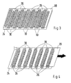
- a second embodiment in the same components with the same Reference numerals are provided, which are provided in the lower housing wall 24 Openings 26 monitored by flexible flaps 32.
- the z. B. rubber o. ⁇ . Materials existing flaps 32 are on a longitudinal side of the rectangular openings 26th hinged and adapted in size to the dimensions of the openings 26 so that they in the closed position (see Fig. 5, 7), the openings 26 completely close.
- the flaps 32 close at idle or at low load and speed of the internal combustion engine due to the air filter housing 12th prevailing pressure conditions the openings 26, while at high load and Speed by the rising negative pressure in the air filter housing 12, the flaps 32nd automatically open inwards, so that a corresponding airborne sound passage is possible.
Landscapes
- Engineering & Computer Science (AREA)
- Chemical & Material Sciences (AREA)
- Combustion & Propulsion (AREA)
- Mechanical Engineering (AREA)
- General Engineering & Computer Science (AREA)
- Physics & Mathematics (AREA)
- Acoustics & Sound (AREA)
- Multimedia (AREA)
- Filtering Of Dispersed Particles In Gases (AREA)
- Air-Conditioning For Vehicles (AREA)
Abstract
Description
- Fig. 1
- die schematische Darstellung eines Luftfiltergehäuses in einem ersten Betriebszustand,
- Fig. 2
- eine schematische Darstellung des Luftfiltergehäuses in einem zweiten Betriebszustand,
- Fig. 3
- die schematische Darstellung eines Schieberegisters in einer ersten Betriebsstellung,
- Fig. 4
- die schematische Darstellung eines Schieberegisters in einer zweiten Betriebsstellung,
- Fig. 5
- die schematische Darstellung eines Luftfiltergehäuses gemäß einem zweiten Ausführungsbeispiel in einem ersten Betriebszustand,
- Fig. 6
- die schematische Darstellung eines Luftfiltergehäuses gemäß einem zweiten Ausführungsbeispiel in einem zweiten Betriebszustand,
- Fig. 7
- die schematische Darstellung flexibler Klappen in einer ersten Betriebsstellung und
- Fig. 8
- die schematische Darstellung flexibler Klappen in einer zweiten Betriebsstellung.
Claims (6)
- Luftfilter für eine Brennkraftmaschine mit einem Luftfiltergehäuse, dessen Gehäusewände einen Filterraum umschließen, in dem ein Filterelement angeordnet ist, sowie mit einem Einlass (14) und einem Auslass (16), dadurch gekennzeichnet, dass mindestens in einer Gehäusewand (24) des Luftfiltergehäuses (12) Öffnungen (26) eingebracht sind, die in Abhängigkeit vom Betriebszustand der Brennkraftmaschine verschließbar sind, und umgekehrt.
- Luftfilter nach Anspruch 1, dadurch gekennzeichnet, dass im Luftfiltergehäuse (12) ein mit Öffnungen (30) versehenes und im Luftfiltergehäuse (12) geführtes Plattenelement (28) vorgesehen ist, das verschiebbar zu der mit den Öffnungen (26) versehenen Gehäusewand (24) angeordnet ist.
- Luftfilter nach Anspruch 2, dadurch gekennzeichnet, dass das Plattenelement (28) von einer Unterdruckdose (34) gesteuert ist, die an einen Unterdruckspeicher angeschlossen ist.
- Luftfilter nach einem der vorhergehenden Ansprüche, dadurch gekennzeichnet, dass das Plattenelement (28) als Unterboden auf der Bodenwand (24) des Luftfiltergehäuses (12) aufliegt.
- Luftfilter nach Anspruch 1, dadurch gekennzeichnet, dass die Öffnungen (26) durch flexible Klappen (32) überwacht sind.
- Luftfilter nach Anspruch 5, dadurch gekennzeichnet, dass die Klappen (32) in Abhängigkeit von den Druckverhältnissen im Luftfiltergehäuse (12) gesteuert sind.
Applications Claiming Priority (4)
| Application Number | Priority Date | Filing Date | Title |
|---|---|---|---|
| DE10205416 | 2002-02-09 | ||
| DE10205416 | 2002-02-09 | ||
| DE10213604 | 2002-03-27 | ||
| DE10213604A DE10213604A1 (de) | 2002-02-09 | 2002-03-27 | Luftfilter für eine Brennkraftmaschine |
Publications (2)
| Publication Number | Publication Date |
|---|---|
| EP1335124A1 true EP1335124A1 (de) | 2003-08-13 |
| EP1335124B1 EP1335124B1 (de) | 2004-12-29 |
Family
ID=27614272
Family Applications (1)
| Application Number | Title | Priority Date | Filing Date |
|---|---|---|---|
| EP03001407A Expired - Lifetime EP1335124B1 (de) | 2002-02-09 | 2003-01-22 | Luftfilter für eine Brennkraftmaschine |
Country Status (2)
| Country | Link |
|---|---|
| US (1) | US6824591B2 (de) |
| EP (1) | EP1335124B1 (de) |
Cited By (1)
| Publication number | Priority date | Publication date | Assignee | Title |
|---|---|---|---|---|
| DE102007026416B4 (de) * | 2007-06-06 | 2014-09-04 | Audi Ag | Vorrichtung zur Beeinflussung des Ansauggeräusches einer Brennkraftmaschine |
Families Citing this family (6)
| Publication number | Priority date | Publication date | Assignee | Title |
|---|---|---|---|---|
| DE10352704A1 (de) * | 2003-11-12 | 2005-06-16 | Mann + Hummel Gmbh | Vorrichtung zur Geräuschübertragung in einem Kraftfahrzeug mit Brennkraftmaschine |
| CN100441855C (zh) * | 2006-04-20 | 2008-12-10 | 朱益民 | 一种空气滤清器 |
| US7635402B2 (en) * | 2006-12-22 | 2009-12-22 | Nissan Technical Center North America, Inc. | Air filter status evaluator |
| DE102007034518A1 (de) * | 2007-07-24 | 2009-01-29 | Dr. Ing. H.C. F. Porsche Aktiengesellschaft | Luftfilter für eine Luftsauganlage einer mehrzylindrischen Brennkraftmaschine |
| CN102146861A (zh) * | 2010-02-09 | 2011-08-10 | 福特环球技术公司 | 内燃发动机的进气系统和用于操作所述类型的系统的方法 |
| JP5685422B2 (ja) * | 2010-11-19 | 2015-03-18 | 本田技研工業株式会社 | コージェネレーション装置 |
Citations (4)
| Publication number | Priority date | Publication date | Assignee | Title |
|---|---|---|---|---|
| DE1052169B (de) * | 1954-04-20 | 1959-03-05 | Sigismond Wilman | Ansauggeraeuschdaempfer |
| EP0242797A1 (de) * | 1986-04-24 | 1987-10-28 | Bayerische Motoren Werke Aktiengesellschaft, Patentabteilung AJ-3 | Ansauggeräuschdämpfer, insbesondere für Brennkraftmaschinen |
| JPH10339225A (ja) * | 1997-06-10 | 1998-12-22 | Toyota Motor Corp | 車載内燃機関の吸気装置 |
| DE19811051A1 (de) * | 1998-03-13 | 1999-09-16 | Mann & Hummel Filter | Luftansaugeinrichtung für einen Verbrennungsmotor |
Family Cites Families (17)
| Publication number | Priority date | Publication date | Assignee | Title |
|---|---|---|---|---|
| US1173403A (en) * | 1914-11-13 | 1916-02-29 | Joseph L Anderson | Heater and muffler. |
| US1200688A (en) * | 1916-04-12 | 1916-10-10 | Joseph L Anderson | Heater and muffler. |
| US2636125A (en) * | 1948-04-10 | 1953-04-21 | Bell Telephone Labor Inc | Selective electromagnetic wave system |
| US2755882A (en) * | 1952-04-22 | 1956-07-24 | Maccaferri Mario | Acoustic tiles |
| US2788086A (en) * | 1952-11-15 | 1957-04-09 | Houdaille Industries Inc | Air cleaner with dual air intake |
| US2848065A (en) * | 1956-02-15 | 1958-08-19 | Purolator Products Inc | Air cleaner |
| US2904129A (en) * | 1956-09-20 | 1959-09-15 | Gen Motors Corp | Low pass filter type cleaner silencer unit |
| US3209520A (en) * | 1962-01-11 | 1965-10-05 | Ford Motor Co | Air cleaner and silencer |
| US4124091A (en) * | 1975-12-24 | 1978-11-07 | Toyota Jidosha Kogyo Kabushiki Kaisha | Silencer for an internal combustion engine |
| DE2714100C2 (de) * | 1977-03-30 | 1985-05-02 | Volkswagenwerk Ag, 3180 Wolfsburg | Luftansaugstutzen für eine Brennkraftmaschine |
| JPS588937Y2 (ja) * | 1977-04-20 | 1983-02-17 | トヨタ自動車株式会社 | 騒音低下ク−ルエアインテ−クノ−ズ |
| US4713097A (en) * | 1987-02-27 | 1987-12-15 | Ford Motor Company | Integrated engine air cleaner and venturi resonator |
| DE4013848A1 (de) * | 1990-04-30 | 1991-10-31 | Vdo Schindling | Einrichtung zur daempfung des ansauggeraeusches bei dieselmotoren |
| US5241512A (en) * | 1991-04-25 | 1993-08-31 | Hutchinson 2 | Acoustic protection material and apparatus including such material |
| DE19940610A1 (de) | 1999-08-27 | 2001-03-01 | Mann & Hummel Filter | Luftfilter |
| DE50309968D1 (de) * | 2002-03-27 | 2008-07-24 | Porsche Ag | Luftfilter für eine Brennkraftmaschine |
| US6852151B2 (en) * | 2002-06-03 | 2005-02-08 | Siemens Vdo Automotive Inc. | Air cleaner and resonator assembly |
-
2003
- 2003-01-22 EP EP03001407A patent/EP1335124B1/de not_active Expired - Lifetime
- 2003-02-10 US US10/361,009 patent/US6824591B2/en not_active Expired - Fee Related
Patent Citations (4)
| Publication number | Priority date | Publication date | Assignee | Title |
|---|---|---|---|---|
| DE1052169B (de) * | 1954-04-20 | 1959-03-05 | Sigismond Wilman | Ansauggeraeuschdaempfer |
| EP0242797A1 (de) * | 1986-04-24 | 1987-10-28 | Bayerische Motoren Werke Aktiengesellschaft, Patentabteilung AJ-3 | Ansauggeräuschdämpfer, insbesondere für Brennkraftmaschinen |
| JPH10339225A (ja) * | 1997-06-10 | 1998-12-22 | Toyota Motor Corp | 車載内燃機関の吸気装置 |
| DE19811051A1 (de) * | 1998-03-13 | 1999-09-16 | Mann & Hummel Filter | Luftansaugeinrichtung für einen Verbrennungsmotor |
Non-Patent Citations (1)
| Title |
|---|
| PATENT ABSTRACTS OF JAPAN vol. 1999, no. 03 31 March 1999 (1999-03-31) * |
Cited By (1)
| Publication number | Priority date | Publication date | Assignee | Title |
|---|---|---|---|---|
| DE102007026416B4 (de) * | 2007-06-06 | 2014-09-04 | Audi Ag | Vorrichtung zur Beeinflussung des Ansauggeräusches einer Brennkraftmaschine |
Also Published As
| Publication number | Publication date |
|---|---|
| US6824591B2 (en) | 2004-11-30 |
| EP1335124B1 (de) | 2004-12-29 |
| US20030172812A1 (en) | 2003-09-18 |
Similar Documents
| Publication | Publication Date | Title |
|---|---|---|
| EP1224389B1 (de) | Ansaugsystem mit luftfilter | |
| EP1350945B1 (de) | Luftfilter für eine Brennkraftmaschine | |
| DE102009035349B4 (de) | Steuervorrichtung für den Kühlmittelfluss im Kühlkreislauf einer Brennkraftmaschine | |
| WO1999047807A1 (de) | Luftansaugeinrichtung für einen verbrennungsmotor | |
| DE3321804A1 (de) | Vorrichtung zum abfuehren von warmluft aus dem motorraum von kraftwagen | |
| EP1172549B1 (de) | Kraftstofffilter | |
| DE20109702U1 (de) | Luftfiltersystem | |
| EP2221097A1 (de) | Filtereinrichtung zur Kohlenwasserstoffadsorption | |
| EP1335124B1 (de) | Luftfilter für eine Brennkraftmaschine | |
| AT408480B (de) | Drosselrückschlagventil und verfahren zu dessen herstellung | |
| DE10257299B4 (de) | Einrichtung zur Rohluftansaugung für eine Brennkraftmaschine | |
| DE19931374A1 (de) | Behälter zur Aufnahme von Verdampfungsemissionen in einem Kraftfahrzeug | |
| DE10213604A1 (de) | Luftfilter für eine Brennkraftmaschine | |
| DE10308084A1 (de) | Kühleinrichtung für ein Kraftfahrzeug-Antriebsaggregat | |
| DE10053145A1 (de) | Ansaugsystem | |
| DE19725336A1 (de) | Anlage zur Kühlung der Batterie eines mit einer Brennkraftmaschine versehenen Kraftfahrzeugs | |
| DE3121895A1 (de) | Verzoegerungsventil | |
| EP0688270B1 (de) | Heizkreislauf-system eines fahrzeuges | |
| DE2451148C3 (de) | Abgasrückführeinrichtung bei Verbrennungsmotoren | |
| DE102010038346A1 (de) | Filtereinrichtung | |
| DE2726848A1 (de) | Steuerung eines automatischen stufengetriebes in einem automobil | |
| DE4034851A1 (de) | Vorrichtung zur geraeusch- und schwingungsminderung an schiebedachoeffnungen von kraftfahrzeugen | |
| DE2422390A1 (de) | Kraftfahrzeug, insbesondere omnibus mit einer schalldaempfeinrichtung | |
| EP1118764B1 (de) | Kraftstoffversorgung für eine Kraftfahrzeug-Brennkraftmaschine | |
| DE3149249A1 (de) | Ansaugsystem fuer einen verbrennungsmotor |
Legal Events
| Date | Code | Title | Description |
|---|---|---|---|
| PUAI | Public reference made under article 153(3) epc to a published international application that has entered the european phase |
Free format text: ORIGINAL CODE: 0009012 |
|
| AK | Designated contracting states |
Designated state(s): AT BE BG CH CY CZ DE DK EE ES FI FR GB GR HU IE IT LI LU MC NL PT SE SI SK TR |
|
| AX | Request for extension of the european patent |
Extension state: AL LT LV MK RO |
|
| 17P | Request for examination filed |
Effective date: 20040213 |
|
| AKX | Designation fees paid |
Designated state(s): DE FR GB IT |
|
| 17Q | First examination report despatched |
Effective date: 20040330 |
|
| GRAP | Despatch of communication of intention to grant a patent |
Free format text: ORIGINAL CODE: EPIDOSNIGR1 |
|
| GRAS | Grant fee paid |
Free format text: ORIGINAL CODE: EPIDOSNIGR3 |
|
| GRAA | (expected) grant |
Free format text: ORIGINAL CODE: 0009210 |
|
| AK | Designated contracting states |
Kind code of ref document: B1 Designated state(s): DE FR GB IT |
|
| REG | Reference to a national code |
Ref country code: GB Ref legal event code: FG4D Free format text: NOT ENGLISH |
|
| REG | Reference to a national code |
Ref country code: IE Ref legal event code: FG4D Free format text: GERMAN |
|
| REF | Corresponds to: |
Ref document number: 50300213 Country of ref document: DE Date of ref document: 20050203 Kind code of ref document: P |
|
| GBT | Gb: translation of ep patent filed (gb section 77(6)(a)/1977) |
Effective date: 20050413 |
|
| PLBE | No opposition filed within time limit |
Free format text: ORIGINAL CODE: 0009261 |
|
| STAA | Information on the status of an ep patent application or granted ep patent |
Free format text: STATUS: NO OPPOSITION FILED WITHIN TIME LIMIT |
|
| ET | Fr: translation filed | ||
| 26N | No opposition filed |
Effective date: 20050930 |
|
| PGFP | Annual fee paid to national office [announced via postgrant information from national office to epo] |
Ref country code: IT Payment date: 20080122 Year of fee payment: 6 |
|
| REG | Reference to a national code |
Ref country code: FR Ref legal event code: TP |
|
| REG | Reference to a national code |
Ref country code: FR Ref legal event code: CD |
|
| REG | Reference to a national code |
Ref country code: FR Ref legal event code: TP |
|
| PG25 | Lapsed in a contracting state [announced via postgrant information from national office to epo] |
Ref country code: IT Free format text: LAPSE BECAUSE OF NON-PAYMENT OF DUE FEES Effective date: 20090122 |
|
| REG | Reference to a national code |
Ref country code: GB Ref legal event code: 732E Free format text: REGISTERED BETWEEN 20110310 AND 20110316 |
|
| REG | Reference to a national code |
Ref country code: GB Ref legal event code: 732E Free format text: REGISTERED BETWEEN 20110331 AND 20110406 |
|
| PGFP | Annual fee paid to national office [announced via postgrant information from national office to epo] |
Ref country code: FR Payment date: 20110202 Year of fee payment: 9 |
|
| PGFP | Annual fee paid to national office [announced via postgrant information from national office to epo] |
Ref country code: GB Payment date: 20110120 Year of fee payment: 9 |
|
| GBPC | Gb: european patent ceased through non-payment of renewal fee |
Effective date: 20120122 |
|
| REG | Reference to a national code |
Ref country code: FR Ref legal event code: ST Effective date: 20120928 |
|
| PG25 | Lapsed in a contracting state [announced via postgrant information from national office to epo] |
Ref country code: GB Free format text: LAPSE BECAUSE OF NON-PAYMENT OF DUE FEES Effective date: 20120122 |
|
| PG25 | Lapsed in a contracting state [announced via postgrant information from national office to epo] |
Ref country code: FR Free format text: LAPSE BECAUSE OF NON-PAYMENT OF DUE FEES Effective date: 20120131 |
|
| PGFP | Annual fee paid to national office [announced via postgrant information from national office to epo] |
Ref country code: DE Payment date: 20171211 Year of fee payment: 16 |
|
| REG | Reference to a national code |
Ref country code: DE Ref legal event code: R119 Ref document number: 50300213 Country of ref document: DE |
|
| PG25 | Lapsed in a contracting state [announced via postgrant information from national office to epo] |
Ref country code: DE Free format text: LAPSE BECAUSE OF NON-PAYMENT OF DUE FEES Effective date: 20190801 |