EP1335050A2 - Textilverarbeitungsmaschine mit einem Faserförderkanal und einer Faserführungsfläche - Google Patents
Textilverarbeitungsmaschine mit einem Faserförderkanal und einer Faserführungsfläche Download PDFInfo
- Publication number
- EP1335050A2 EP1335050A2 EP03000507A EP03000507A EP1335050A2 EP 1335050 A2 EP1335050 A2 EP 1335050A2 EP 03000507 A EP03000507 A EP 03000507A EP 03000507 A EP03000507 A EP 03000507A EP 1335050 A2 EP1335050 A2 EP 1335050A2
- Authority
- EP
- European Patent Office
- Prior art keywords
- fiber
- channel
- edge
- deflection point
- guide surface
- Prior art date
- Legal status (The legal status is an assumption and is not a legal conclusion. Google has not performed a legal analysis and makes no representation as to the accuracy of the status listed.)
- Granted
Links
Images


Classifications
-
- D—TEXTILES; PAPER
- D01—NATURAL OR MAN-MADE THREADS OR FIBRES; SPINNING
- D01H—SPINNING OR TWISTING
- D01H4/00—Open-end spinning machines or arrangements for imparting twist to independently moving fibres separated from slivers; Piecing arrangements therefor; Covering endless core threads with fibres by open-end spinning techniques
- D01H4/02—Open-end spinning machines or arrangements for imparting twist to independently moving fibres separated from slivers; Piecing arrangements therefor; Covering endless core threads with fibres by open-end spinning techniques imparting twist by a fluid, e.g. air vortex
-
- D—TEXTILES; PAPER
- D01—NATURAL OR MAN-MADE THREADS OR FIBRES; SPINNING
- D01H—SPINNING OR TWISTING
- D01H1/00—Spinning or twisting machines in which the product is wound-up continuously
- D01H1/11—Spinning by false-twisting
- D01H1/115—Spinning by false-twisting using pneumatic means
-
- D—TEXTILES; PAPER
- D01—NATURAL OR MAN-MADE THREADS OR FIBRES; SPINNING
- D01H—SPINNING OR TWISTING
- D01H4/00—Open-end spinning machines or arrangements for imparting twist to independently moving fibres separated from slivers; Piecing arrangements therefor; Covering endless core threads with fibres by open-end spinning techniques
- D01H4/38—Channels for feeding fibres to the yarn forming region
Definitions
- the present invention relates to a device for producing a spun Thread from a staple fiber association according to the preamble of claim 1.
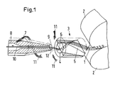
- Such devices are known in textile technology and are used in air spinning processes used. Such a device is disclosed, for example, by the document EP 854 214 (equivalent to US 5,927,062), which is shown in FIG. 1.
- the fiber guide element 3 has a fiber feed channel 4 with a helical fiber guide surface 5 on.
- the staple fiber bandage 1 is guided through the fiber guide surface 5, which ends at a fiber delivery edge 6.
- At a certain distance from the The fiber guide element 3, or to the fiber delivery edge 6, is a spindle 7 with a yarn guide channel 8 and an inlet mouth associated with the yarn guide channel 8 9 provided.
- a fluid device for creating a vortex flow around the inlet mouth 9 provided (fluid device not shown).
- the fluid device generates a vortex flow 11 around the inlet mouth 9, or the Spindle 7.
- the free fiber ends 12 are laid by the vortex flow 11 of the staple fiber dressing 1 around the inlet mouth 9.
- a staple thread 10 is thus created in the staple fiber association 1.
- the present invention is concerned with the design of fiber guide elements, as shown in Figure 1.
- the invention is particularly concerned with the design of fiber feed channels and the associated fiber guide surfaces.
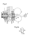
- FIG. 1 shows essentially the same components as in FIG shown in Figure 1 (with a change, see Figure 2a).
- the outlet roller pair 2 and the spindle 7 with the yarn guide channel 8 can be seen.
- Analogous to FIG. 1 also shows a fluid device 13 for generating a vortex flow shown.
- the fluid device 13 consists of several bores, one of which Fluid (preferably air) is blown into space 14 under pressure. The blown Compressed air creates a vortex flow around the inlet mouth 9 of the spindle 7.
- the fiber guide element 3a consists of two components.
- FIG. 2a the fiber guide element part 3b of FIG. 2 is shown in a three-dimensional View shown.
- the fiber guide element part 3b not a helical, but a flat fiber guide surface 15.
- the fiber guiding element part 3b has a blunt cone 16 on. The purpose of this cone 16 is to produce a so-called false yarn core. This is to prevent a false twist (twisting of the staple fiber association) from the inlet mouth 9 backwards through the fiber guide element 3 propagates against the nip of the pair of output rollers 2.
- a false twist prevents a real rotation or twisting of the free fiber ends 12 to form a Yarn, because the core of the staple fiber association rotates with the free fiber ends 12 with. This means that the false twist would prevent the fibers from spinning.
- an attempt is made to stop the swirl by the helical one To realize fiber guide surface 5, which a twisting of the staple fiber association 1 against the outlet rollers 2 should be impossible.
- FIGS. 1 and 2 The known prior art of FIGS. 1 and 2 has various disadvantages, which to fix or minimize the device according to the invention tries.
- Another disadvantage is that the one shown in the figures Twist stop can hinder optimal fiber guidance.
- Another critical point of the published or unpublished writings mentioned so far has not been solved satisfactorily, the guidance of the fiber structure between the Clamp line of the outlet roller pair and the fiber guide element (see for example Figure 1 or 2).
- the staple fiber bandage consisting of individual parallelized and untwisted fibers has a relatively low strength, or one relatively low internal cohesion.
- the object of the present invention is accordingly the disadvantages of the prior art Fix or minimize technology.
- the fiber guidance should in particular be such will design that the yarn quality of the spun thread is improved.
- FIG. 3 shows a device for producing a spun thread with an inventive designed fiber guiding element 3c, a fluid device 13 for production a vortex flow 11 around the inlet mouth 9 of a spindle 7 with an integrated Yarn guide channel 8.
- FIG. 3 shows a cross section of the device in parallel to the direction of conveyance of the staple fiber bandage (which is not shown in this figure becomes).
- the fiber guide element 3c shown in the figure has an inventive Fiber guide surface 18 with a deflection point 17.
- the deflection point 17 is in this example by designing the fiber guide surface 18 according to the invention educated.
- the fiber guide surface 18 actually exists from two flat surfaces, the common intersection of which is the deflection point 17 forms.
- This design of the fiber guide surface makes the fibers of the staple fiber association in an essentially flat arrangement guided.
- the fiber delivery edge 6 also contributes to this flat arrangement.
- the deflection point 17 (which is formed here as an additional edge) is dimensioned so that that the fibers of the staple fiber association are deflected such that the free Fiber ends of the fibers, which are in the staple fiber structure, can lift off (see Fig. 4).
- the front as well as the rear fiber ends especially those fibers lifted off that are on the surface of the staple fiber dressing or immediately below. Be at the deflection point 17 both front and rear fiber ends lifted off.
- Free fiber ends are understood to mean those ends that do not lie within the staple fiber structure or are not connected to other fibers are and can be captured by the vortex flow.
- By increasing the number of free fiber ends increases the number of wrapping fibers in the Yarn and the quality of the spinning process itself. Overall, this can be done so increase the yarn quality.
- the design of a deflection point such that the inventive The effect of lifting off the free fiber ends is essential.
- the applicant's international application PCT-CH 01-00569 shows in her Figures and explains in their description an increase in their fiber guide area.
- the design of the fiber guide surface according to the invention surprisingly has a further advantage over the prior art.
- the reduction in the cross section A of the fiber conveying channel 4 within a region has shown that the air volume V flowing through was surprisingly increased.
- the increased air flow V made it possible to substantially improve the fiber guidance between the outlet rollers and the entrance of the fiber guidance element 3c, that is to say in front of the fiber guidance element.
- the number of production interruptions, caused by tearing of the staple fiber association immediately after the outfeed rollers, could be reduced. A measurable improvement in yarn quality was also found.
- the cross sections A of the fiber conveying channel up to the deflection point preferably have an amount of 0.5 to 10 mm 2 , preferably 2 to 5 mm 2 .
- FIG. 3a shows a section along the section lines I-I of the inventive The device of FIG. 3.
- the flat fiber guide surface according to the invention can be seen particularly well 18 and the fiber delivery edge 6.
- the fiber guide surface according to the invention has a convex, concave or selected surface. This deviation the optimal shape of the flat surface is particularly recommended in cases where the staple fiber dressing has "sticky” or “slippery” fibers.
- the embodiment according to FIG. 3b with the concave fiber guide surface 18.1 is suitable especially for "slippery" fibers, which have weak, mutual adhesion exhibit.
- a convex variant of the fiber guide surface according to the invention 18.2 can be suitable for "sticky" fibers, which mutually have a stronger adhesion (the cohesion of the fibers is loosened, which means more free fiber ends can arise).
- 3d shows a wavy fiber guide surface 18.3. This can help maintain a flatter arrangement of fibers in the staple fiber structure. 3e has already been explained; it shows like the cross section B of the fiber feed channel after the redirection point (outline shown in dashed lines) larger by the hatched area is.
- Fig. 4 shows the same embodiment of the invention as Fig. 3.
- the staple fiber dressing 20 can be seen.
- the free fiber ends can at the deflection point 17 Lift 19 of the fibers in the staple fiber structure 20 (shown as an example).
- the free fiber ends 19 have both front and rear fiber ends include (corresponding to the left or right of the deflection point 17).
- These free fiber ends can do better from the vortex flow 11 are detected and placed around the inlet mouth 9. To this In this way, more free fiber ends can be spun or more wrapping fibers can be produced what improves the spinning process itself.
- 4 a shows a section I-I 4. It can be seen how the staple fiber structure 20 has a flat arrangement.
- FIG. 5 shows a further variant of the invention, in which the fiber guide surface 22 has a cylindrical trough (fiber guide surface before the deflection point 17 is flat). This trough shape of the fiber guide surface 22 leads to a concave fiber delivery edge 6.1.
- the end face 21 of the fiber delivery edge is also shown 6.1.
- FIGS. 5 a and 5 b represent sections of FIG. 5 is the in this embodiment of the invention End face 21 substantially perpendicular to the fiber delivery edge 6.1, respectively to the yarn guide channel 8.
- the end face can also have other shapes.
- FIG. 6 a shows the end face 21 may be vertical with a straight delivery edge 6.
- 6b shows a convex shape (21.1) or, as shown in FIG. 6c, one have a concave shape (21.2).
- Variants 6b and 6c are also shown in FIGS. in which the fiber delivery edge 6 and the end face 21 are not the full width of the fiber guide element Own 3c.
- the width of the fiber guide element can vary 3c taper conically in the vicinity of the fluid device 13, see above that the fiber delivery edge 6 and the end face 22.1, or 22.2, only that Have width G (compare with Fig. 6 a).
Landscapes
- Engineering & Computer Science (AREA)
- Mechanical Engineering (AREA)
- Textile Engineering (AREA)
- Yarns And Mechanical Finishing Of Yarns Or Ropes (AREA)
- Spinning Or Twisting Of Yarns (AREA)
- Preliminary Treatment Of Fibers (AREA)
- Treatment Of Fiber Materials (AREA)
Abstract
Description
- Fig. 1
- Stand der Technik aus der Schrift EP 854 214
- Fig. 2 und 2 a
- Stand der Technik gemäss der JP 3-10 63 68
- Fig. 3
- Eine mögliche Ausführungsform der Erfindung gemäss den Schnittlinien II-II der Fig. 3a
- Fig. 3 a
- Ein Schnitt gemäss den Schnittlinien I-I von Fig. 3
- Fig. 3b, 3c, 3d
- Verschiedene Varianten für die Ausführung der Faserführungsfläche entsprechend dem Querschnitt der Fig. 3a
- Fig. 3e
- Querschnitte des Faserförderkanals entsprechend Fig. 3
- Fig. 4
- Einen Querschnitt der erfindungsgemässen Vorrichtung gemäss der Fig. 3 mit einem Stapelfaserverband und einem gesponnenen Faden
- Fig. 4a
- Querschnitt gemäss den Schnittlinien I-I von Fig. 4
- Fig. 5 und 5a
- Weitere Ausführungsform der Erfindung mit einer kreissegmentförmigen Vertiefung der Faserabgabekante
- Fig. 5b
- Ein weiterer Querschnitt gemäss den Schnittlinien III-III der Fig. 5
- Fig. 6a, 6b
- Weitere Ausführungsformen der Erfindung mit unterschiedlichen Stirnflächen
- Fig. 6c
- Eine weitere Variante der Erfindung gemäss der Fig. 3
- 1
- Stapelfaserverband
- 2
- Auslaufwalzenpaar
- 3
- Faserführungselement
- 3a
- Faserführungselement
- 3b
- Faserführungselement-Teil
- 3c
- erfindungsgemäss gestaltetes Faserführungselement
- 4
- Faserförderkanal
- 5
- wendelförmige Faserführungsfläche
- 6
- Faserabgabekante
- 6.1
- konkave Faserabgabekante
- 7
- Spindel
- 8
- Garnführungskanal
- 9
- Einlassmündung
- 10
- gesponnener Faden
- 11
- Wirbelströmung
- 12
- freie Faserenden
- 13
- Fluideinrichtung
- 14
- Raum
- 15
- ebene Faserführungsfläche
- 16
- stumpfer Kegel
- 17
- Umlenkstelle
- A
- Querschnitt vor Umlenkstelle
- B
- Querschnitt nach Umlenkstelle
- 18
- erfindungsgemässe Faserführungsfläche
- 18.1
- Variante der erfindungsgemässen Faserführungsfläche
- 18.2
- Variante der erfindungsgemässen Faserführungsfläche
- 18.3
- Variante der erfindungsgemässen Faserführungsfläche
- 19
- freie Faserenden
- 20
- Stapelfaserverband mit flacher Anordnung der Fasern
- 21
- Stirnfläche
- 21.1
- konvexe Stirnfläche
- 21.2
- konkave Stirnfläche
- 22
- Faserführungsfläche mit zylinderförmiger Mulde
- 23
- Mittellinie des Garnführungskanals
- C
- Abstand von der Umlenkstelle (Zusatzkante) bis zur Faserabgabekante (parallel zur Mittellinie des Garnführungskanals)
- D
- Abstand von der Umlenkstelle (Zusatzkante) bis zur Faserabgabekante (vertikal zur Mittellinie des Garnführungskanals)
- E
- Abstand von der Faserabgabekante bis zur Einlassmündung der Spindel (parallel zur Mittellinie des Garnführungskanals)
- F
- Abstand von der Faserabgabekante bis zur Mittellinie des Garnführungskanals (vertikal zur Mittellinie des Garnführungskanals)
- G
- Breite der reduzierten Faserabgabekante
Claims (13)
- Vorrichtung zur Herstellung eines gesponnenen Fadens (10) aus einem Stapelfaserverband (1), enthaltend einen Faserförderkanal mit einer Faserführungsfläche, wobei die Faserführungsfläche an einer Faserabgabekante endet,
dadurch gekennzeichnet, dass
die Faserführungsfläche (18, 18.1, 18.2, 18.3) die Fasern des Stapelfaserverbandes (20) in einer im wesentlichen flach nebeneinander liegenden Anordnung führt, und
dass
die Faserführungsfläche (18, 18.1, 18.2, 18.3) eine Umlenkstelle (17) aufweist, welche eine Umlenkung der Stapelfaserverbandes (20) verursacht, wobei die Umlenkung derart ist, dass die freien Faserenden (19) der Fasern im Stapelfaserverband (20) abheben. - Vorrichtung nach Anspruch 1, dadurch gekennzeichnet, dass der Querschnitt (A) des Faserförderkanals (4) bis zur Umlenkstelle (17) im wesentlichen konstant bleibt, wobei der Querschnitt (B) des Faserförderkanals (4) nach der Umlenkstelle bis zum Ende des Faserförderkanals (4) zunimmt.
- Vorrichtung nach Anspruch 1 oder 2, dadurch gekennzeichnet, dass die Umlenkstelle (17) durch Gestaltung der Faserführungsfläche (18, 18.1,18.2, 18.3) gebildet wird.
- Vorrichtung nach Anspruch 3, dadurch gekennzeichnet, dass die Umlenkstelle (17) durch eine Zusatzkante gebildet wird, ab welcher die Faserführungsfläche (18, 18.1, 18.2, 18.3) mit einer Neigung zur ursprünglichen Ebene weiterführt.
- Vorrichtung nach Anspruch 4, dadurch gekennzeichnet, dass die Zusatzkante einen vorgegebenen Abstand (C) von der Faserabgabekante (6) aufweist, wobei der Abstand (C) einen Betrag von 1 mm bis 4 mm, bevorzugt von 1.5 mm bis 2.5 mm hat.
- Vorrichtung nach Anspruch 4, dadurch gekennzeichnet, dass die Zusatzkante von der Faserabgabekante (6) einen vorgegebenen Abstand (D) aufweist, wobei der Abstand (D) von 0.2 mm bis 1 mm, bevorzugt von 0.4 mm bis 0.7 mm beträgt.
- Vorrichtung nach Anspruch 4, dadurch gekennzeichnet, dass die Form der Zusatzkante gerade, konkav gebogen, konvex gebogen, oder kombiniert konkav-konvexkonkav gebogen ist.
- Vorrichtung nach einem der vorangehenden Ansprüchen, dadurch gekennzeichnet, dass die Faserabgabekante (6) eine konkave Vertiefung (6.1) aufweist.
- Vorrichtung nach einem der vorangehenden Ansprüchen, dadurch gekennzeichnet, dass die Faserabgabekante (6) eine zur Mittellinie (23) des Garnführungskanals (8) im wesentlichen senkrechte Stirnfläche (21) aufweist.
- Vorrichtung nach dem vorangehenden Anspruch, dadurch gekennzeichnet, dass die Stirnfläche konkav (21.2), konvex (21.1) oder wellenförmig gestaltet ist.
- Vorrichtung nach einem der vorangehenden Ansprüchen, dadurch gekennzeichnet, dass der Querschnitt (A) des Faserförderkanals (4) bis zur Umlenkstelle (17) einen Betrag von 0.5 bis 10 mm2, bevorzugt von 2 bis 5 mm2 aufweist.
- Vorrichtung nach einem der vorangehenden Ansprüchen, dadurch gekennzeichnet, dass, in Förderrichtung der Fasern gesehen, nach dem Faserförderkanal (4) und der Faserabgabekante (6, 6.1),
in einem Abstand (E) eine Spindel (7) angeordnet ist, die einen Garnführungskanal (8) mit einer Einlassmündung (9) aufweist,
wobei um die Einlassmündung (9) des Garnführungskanals (8) eine Fluideinrichtung (13) zur Erzeugung einer Wirbelströmung (11) um die Einlassmündung (9) vorgesehen ist. - Vorrichtung nach einem der vorangehenden Ansprüchen, dadurch gekennzeichnet, dass die Faserabgabekante (6, 6.1)
den vorgegebenen Abstand (E) von der Einlassmündung (9) aufweist, wobei der Abstand (E) von 0.1 mm bis 1 mm , bevorzugt von 0.3 mm bis 0.7 mm beträgt, und/oder
einen vorgegeben Abstand (F) von der Mittellinie (23) des Garnführungskanals (8) aufweist, wobei der Abstand (F) einen Betrag von 10% bis 40% des Durchmessers des Garnführungskanals (8) aufweist.
Applications Claiming Priority (2)
| Application Number | Priority Date | Filing Date | Title |
|---|---|---|---|
| CH2352002 | 2002-02-12 | ||
| CH2352002 | 2002-02-12 |
Publications (3)
| Publication Number | Publication Date |
|---|---|
| EP1335050A2 true EP1335050A2 (de) | 2003-08-13 |
| EP1335050A3 EP1335050A3 (de) | 2004-01-14 |
| EP1335050B1 EP1335050B1 (de) | 2008-07-16 |
Family
ID=27587789
Family Applications (1)
| Application Number | Title | Priority Date | Filing Date |
|---|---|---|---|
| EP03000507A Expired - Lifetime EP1335050B1 (de) | 2002-02-12 | 2003-01-09 | Textilverarbeitungsmaschine mit einem Faserförderkanal und einer Faserführungsfläche |
Country Status (6)
| Country | Link |
|---|---|
| US (1) | US6928803B2 (de) |
| EP (1) | EP1335050B1 (de) |
| JP (1) | JP4511799B2 (de) |
| CN (1) | CN100537864C (de) |
| AT (1) | ATE401440T1 (de) |
| DE (1) | DE50310137D1 (de) |
Cited By (6)
| Publication number | Priority date | Publication date | Assignee | Title |
|---|---|---|---|---|
| WO2005045105A1 (de) * | 2003-11-11 | 2005-05-19 | Maschinenfabrik Rieter Ag | Spinnstelle mit faserführungselement |
| WO2008110137A1 (de) * | 2007-03-15 | 2008-09-18 | Sipra Patententwicklungs- Und Beteiligungsgesellschaft Mbh | Vorrichtung mit streckwerk zur verarbeitung von fasermaterial |
| EP2813604A1 (de) * | 2013-06-14 | 2014-12-17 | Maschinenfabrik Rieter Ag | Spinndüse sowie damit ausgerüstete Spinnstelle einer Luftspinnmaschine |
| EP2453045A3 (de) * | 2010-11-10 | 2015-12-09 | Murata Machinery, Ltd. | Luftspinnvorrichtung, Spinneinheit und Spinnverfahren unter Verwendung der Luftspinnvorrichtung |
| EP3680373A1 (de) * | 2019-01-08 | 2020-07-15 | Maschinenfabrik Rieter AG | Faserführungselement für eine spinndüse sowie damit ausgestattete spinndüse |
| EP3792381A1 (de) * | 2019-09-13 | 2021-03-17 | Murata Machinery, Ltd. | Pneumatische spinnvorrichtung und pneumatische spinnmaschine |
Families Citing this family (7)
| Publication number | Priority date | Publication date | Assignee | Title |
|---|---|---|---|---|
| EP1332248B9 (de) * | 2000-09-22 | 2016-07-13 | Maschinenfabrik Rieter Ag | Spinnvorrichtung |
| EP1584715A1 (de) * | 2004-04-07 | 2005-10-12 | Maschinenfabrik Rieter Ag | Verfahren zum Herstellen eines Garnes in einer Luftspinnmaschine |
| JP5549551B2 (ja) * | 2010-11-10 | 2014-07-16 | 村田機械株式会社 | 空気紡績装置を用いた紡績方法及び空気紡績装置 |
| DE102013003408A1 (de) * | 2013-02-28 | 2014-08-28 | Oerlikon Textile Gmbh & Co. Kg | Vorrichtung zum pneumatischen Fördern und Führen eines multifilen Fadens |
| CN107735516A (zh) * | 2015-06-19 | 2018-02-23 | 株式会社大赛璐 | 长条状的纤维丝束的开纤物的制造方法 |
| CH712409A1 (de) * | 2016-04-29 | 2017-10-31 | Rieter Ag Maschf | Luftspinnmaschine sowie Verfahren zur Herstellung eines Garns. |
| US10995430B2 (en) * | 2018-11-20 | 2021-05-04 | Amrapur Overseas, Inc. | Yarn manufacturing |
Family Cites Families (18)
| Publication number | Priority date | Publication date | Assignee | Title |
|---|---|---|---|---|
| CS266666B1 (en) * | 1987-04-16 | 1990-01-12 | Havranek Zdenek | Equipment for bundled yarn production in pneumatic spinning nozzle |
| JPH03106368A (ja) | 1989-09-20 | 1991-05-02 | Matsushita Electric Ind Co Ltd | 気泡発生ユニット付き浴槽 |
| US5263310A (en) * | 1990-02-20 | 1993-11-23 | Murata Kikai Kabushiki Kaisha | Spinning apparatus |
| JPH0424221A (ja) * | 1990-05-15 | 1992-01-28 | Murata Mach Ltd | 紡績装置 |
| JPH0465535A (ja) * | 1990-07-04 | 1992-03-02 | Murata Mach Ltd | 紡績装置 |
| JP3106368B2 (ja) | 1991-02-28 | 2000-11-06 | 吉田 康伸 | 空気清浄機 |
| JPH0748673Y2 (ja) * | 1992-02-19 | 1995-11-08 | 村田機械株式会社 | 紡績装置 |
| JP2697575B2 (ja) * | 1993-09-08 | 1998-01-14 | 村田機械株式会社 | 紡績装置 |
| MX9708824A (es) * | 1996-03-15 | 1998-02-28 | Falcon Products Inc | Mesa plegable. |
| US6043846A (en) * | 1996-11-15 | 2000-03-28 | Matsushita Electric Industrial Co., Ltd. | Prediction apparatus and method for improving coding efficiency in scalable video coding |
| JPH10204731A (ja) * | 1997-01-16 | 1998-08-04 | Murata Mach Ltd | 紡績装置 |
| US6125149A (en) * | 1997-11-05 | 2000-09-26 | At&T Corp. | Successively refinable trellis coded quantization |
| US6081554A (en) * | 1998-10-02 | 2000-06-27 | The Trustees Of Columbia University In The City Of New York | Method to control the generated bit rate in MPEG-4 shape coding |
| US6233226B1 (en) * | 1998-12-14 | 2001-05-15 | Verizon Laboratories Inc. | System and method for analyzing and transmitting video over a switched network |
| US6393154B1 (en) * | 1999-11-18 | 2002-05-21 | Quikcat.Com, Inc. | Method and apparatus for digital image compression using a dynamical system |
| EP1332248B9 (de) * | 2000-09-22 | 2016-07-13 | Maschinenfabrik Rieter Ag | Spinnvorrichtung |
| EP1279756A3 (de) * | 2001-07-27 | 2003-11-12 | Maschinenfabrik Rieter Ag | Pneumatische Spinnvorrichtung und Spinnverfahren |
| US7039246B2 (en) * | 2002-05-03 | 2006-05-02 | Qualcomm Incorporated | Video encoding techniques |
-
2003
- 2003-01-09 EP EP03000507A patent/EP1335050B1/de not_active Expired - Lifetime
- 2003-01-09 AT AT03000507T patent/ATE401440T1/de not_active IP Right Cessation
- 2003-01-09 DE DE50310137T patent/DE50310137D1/de not_active Expired - Lifetime
- 2003-02-10 JP JP2003032862A patent/JP4511799B2/ja not_active Expired - Fee Related
- 2003-02-11 CN CNB031044069A patent/CN100537864C/zh not_active Expired - Fee Related
- 2003-02-11 US US10/364,297 patent/US6928803B2/en not_active Expired - Lifetime
Cited By (6)
| Publication number | Priority date | Publication date | Assignee | Title |
|---|---|---|---|---|
| WO2005045105A1 (de) * | 2003-11-11 | 2005-05-19 | Maschinenfabrik Rieter Ag | Spinnstelle mit faserführungselement |
| WO2008110137A1 (de) * | 2007-03-15 | 2008-09-18 | Sipra Patententwicklungs- Und Beteiligungsgesellschaft Mbh | Vorrichtung mit streckwerk zur verarbeitung von fasermaterial |
| EP2453045A3 (de) * | 2010-11-10 | 2015-12-09 | Murata Machinery, Ltd. | Luftspinnvorrichtung, Spinneinheit und Spinnverfahren unter Verwendung der Luftspinnvorrichtung |
| EP2813604A1 (de) * | 2013-06-14 | 2014-12-17 | Maschinenfabrik Rieter Ag | Spinndüse sowie damit ausgerüstete Spinnstelle einer Luftspinnmaschine |
| EP3680373A1 (de) * | 2019-01-08 | 2020-07-15 | Maschinenfabrik Rieter AG | Faserführungselement für eine spinndüse sowie damit ausgestattete spinndüse |
| EP3792381A1 (de) * | 2019-09-13 | 2021-03-17 | Murata Machinery, Ltd. | Pneumatische spinnvorrichtung und pneumatische spinnmaschine |
Also Published As
| Publication number | Publication date |
|---|---|
| JP4511799B2 (ja) | 2010-07-28 |
| EP1335050B1 (de) | 2008-07-16 |
| ATE401440T1 (de) | 2008-08-15 |
| JP2003268636A (ja) | 2003-09-25 |
| CN1438366A (zh) | 2003-08-27 |
| US6928803B2 (en) | 2005-08-16 |
| US20030177751A1 (en) | 2003-09-25 |
| EP1335050A3 (de) | 2004-01-14 |
| CN100537864C (zh) | 2009-09-09 |
| DE50310137D1 (de) | 2008-08-28 |
Similar Documents
| Publication | Publication Date | Title |
|---|---|---|
| EP1223236B1 (de) | Vorrichtung zur Herstellung eines Core-Garns | |
| EP1335050B1 (de) | Textilverarbeitungsmaschine mit einem Faserförderkanal und einer Faserführungsfläche | |
| EP1664404B1 (de) | Vorrichtung zur herstellung von vorgarn mittels luftspinnverfahren und verwendung einer solchen vorrichtung | |
| EP1332248B9 (de) | Spinnvorrichtung | |
| CH692744A5 (de) | Fadenabzugdüse. | |
| DE69713733T2 (de) | Spinnvorrichtung | |
| EP0121602B1 (de) | Falschdralleinheit | |
| EP1664403B1 (de) | Strecke-vorspinnmaschinen-kombination zur herstellung von vorgarn mittels eines luftspinnverfahrens | |
| EP1347084B1 (de) | Luftspinnvorrichtung mit Kanalauskleidung | |
| DE3639031C2 (de) | ||
| EP1644561A1 (de) | Vorrichtung zum herstellen eines gesponnenen fadens aus einem stapelfaserverband | |
| EP1431432B1 (de) | Vorrichtung zum Herstellen eines gesponnenen Fadens | |
| EP2813604B1 (de) | Spinndüse sowie damit ausgerüstete Spinnstelle einer Luftspinnmaschine | |
| EP0305971B1 (de) | Verfahren und Vorrichtung zum Falschdrall-Spinnen | |
| AT391328B (de) | Streckwerk fuer eine ringspinnvorrichtung | |
| EP1584715A1 (de) | Verfahren zum Herstellen eines Garnes in einer Luftspinnmaschine | |
| EP1490539B1 (de) | Pneumatische verdichtungseinrichtung für einen faserverband und verfahren zum pneumatischen verdichten eines faserverbandes | |
| EP3688209B1 (de) | Verdichtereinrichtung | |
| DE4222662B4 (de) | Vorrichtung zum Vorbereiten von Fadenenden | |
| DE3810860A1 (de) | Verfahren und vorrichtung zum turbulenzspinnen zur herstellung von faserbuendelgarn | |
| EP1587974B1 (de) | Vorrichtung zum herstellen eines gesponnenen fadens | |
| EP0208274A1 (de) | Verfahren und Vorrichtung zum Spinnen eines Garnes nach dem Offenend-Friktions-Spinnprinzip | |
| EP0415295B1 (de) | Verfahren zum Falschdrahtspinnen und Vorrichtung zur Durchführung des Verfahrens | |
| DE19608829A1 (de) | Saugwalze für Offenend-Spinnmaschinen | |
| DE3341279C2 (de) | Auflöseeinrichtung für eine OE-Rotor-Spinneinheit |
Legal Events
| Date | Code | Title | Description |
|---|---|---|---|
| PUAI | Public reference made under article 153(3) epc to a published international application that has entered the european phase |
Free format text: ORIGINAL CODE: 0009012 |
|
| AK | Designated contracting states |
Designated state(s): AT BE BG CH CY CZ DE DK EE ES FI FR GB GR HU IE IT LI LU MC NL PT SE SI SK TR |
|
| AX | Request for extension of the european patent |
Extension state: AL LT LV MK RO |
|
| PUAL | Search report despatched |
Free format text: ORIGINAL CODE: 0009013 |
|
| RIN1 | Information on inventor provided before grant (corrected) |
Inventor name: STALDER, DR. HERBERT Inventor name: ARTZT, DR. PETER Inventor name: MUELLER, HEINZ Inventor name: ZIEGLER, KURT Inventor name: ANDEREGG, PETER |
|
| AK | Designated contracting states |
Kind code of ref document: A3 Designated state(s): AT BE BG CH CY CZ DE DK EE ES FI FR GB GR HU IE IT LI LU MC NL PT SE SI SK TR |
|
| AX | Request for extension of the european patent |
Extension state: AL LT LV MK RO |
|
| 17P | Request for examination filed |
Effective date: 20040621 |
|
| AKX | Designation fees paid |
Designated state(s): AT BE BG CH CY CZ DE DK EE ES FI FR GB GR HU IE IT LI LU MC NL PT SE SI SK TR |
|
| R17P | Request for examination filed (corrected) |
Effective date: 20040621 |
|
| 17Q | First examination report despatched |
Effective date: 20070727 |
|
| GRAP | Despatch of communication of intention to grant a patent |
Free format text: ORIGINAL CODE: EPIDOSNIGR1 |
|
| GRAS | Grant fee paid |
Free format text: ORIGINAL CODE: EPIDOSNIGR3 |
|
| GRAA | (expected) grant |
Free format text: ORIGINAL CODE: 0009210 |
|
| AK | Designated contracting states |
Kind code of ref document: B1 Designated state(s): AT BE BG CH CY CZ DE DK EE ES FI FR GB GR HU IE IT LI LU MC NL PT SE SI SK TR |
|
| REG | Reference to a national code |
Ref country code: GB Ref legal event code: FG4D Free format text: NOT ENGLISH |
|
| REG | Reference to a national code |
Ref country code: CH Ref legal event code: EP |
|
| REF | Corresponds to: |
Ref document number: 50310137 Country of ref document: DE Date of ref document: 20080828 Kind code of ref document: P |
|
| REG | Reference to a national code |
Ref country code: IE Ref legal event code: FG4D Free format text: LANGUAGE OF EP DOCUMENT: GERMAN |
|
| NLV1 | Nl: lapsed or annulled due to failure to fulfill the requirements of art. 29p and 29m of the patents act | ||
| PG25 | Lapsed in a contracting state [announced via postgrant information from national office to epo] |
Ref country code: PT Free format text: LAPSE BECAUSE OF FAILURE TO SUBMIT A TRANSLATION OF THE DESCRIPTION OR TO PAY THE FEE WITHIN THE PRESCRIBED TIME-LIMIT Effective date: 20081216 Ref country code: NL Free format text: LAPSE BECAUSE OF FAILURE TO SUBMIT A TRANSLATION OF THE DESCRIPTION OR TO PAY THE FEE WITHIN THE PRESCRIBED TIME-LIMIT Effective date: 20080716 Ref country code: ES Free format text: LAPSE BECAUSE OF FAILURE TO SUBMIT A TRANSLATION OF THE DESCRIPTION OR TO PAY THE FEE WITHIN THE PRESCRIBED TIME-LIMIT Effective date: 20081027 |
|
| PG25 | Lapsed in a contracting state [announced via postgrant information from national office to epo] |
Ref country code: SI Free format text: LAPSE BECAUSE OF FAILURE TO SUBMIT A TRANSLATION OF THE DESCRIPTION OR TO PAY THE FEE WITHIN THE PRESCRIBED TIME-LIMIT Effective date: 20080716 Ref country code: BG Free format text: LAPSE BECAUSE OF FAILURE TO SUBMIT A TRANSLATION OF THE DESCRIPTION OR TO PAY THE FEE WITHIN THE PRESCRIBED TIME-LIMIT Effective date: 20081016 Ref country code: FI Free format text: LAPSE BECAUSE OF FAILURE TO SUBMIT A TRANSLATION OF THE DESCRIPTION OR TO PAY THE FEE WITHIN THE PRESCRIBED TIME-LIMIT Effective date: 20080716 |
|
| REG | Reference to a national code |
Ref country code: IE Ref legal event code: FD4D |
|
| PG25 | Lapsed in a contracting state [announced via postgrant information from national office to epo] |
Ref country code: IE Free format text: LAPSE BECAUSE OF FAILURE TO SUBMIT A TRANSLATION OF THE DESCRIPTION OR TO PAY THE FEE WITHIN THE PRESCRIBED TIME-LIMIT Effective date: 20080716 Ref country code: EE Free format text: LAPSE BECAUSE OF FAILURE TO SUBMIT A TRANSLATION OF THE DESCRIPTION OR TO PAY THE FEE WITHIN THE PRESCRIBED TIME-LIMIT Effective date: 20080716 Ref country code: DK Free format text: LAPSE BECAUSE OF FAILURE TO SUBMIT A TRANSLATION OF THE DESCRIPTION OR TO PAY THE FEE WITHIN THE PRESCRIBED TIME-LIMIT Effective date: 20080716 |
|
| PLBE | No opposition filed within time limit |
Free format text: ORIGINAL CODE: 0009261 |
|
| STAA | Information on the status of an ep patent application or granted ep patent |
Free format text: STATUS: NO OPPOSITION FILED WITHIN TIME LIMIT |
|
| PG25 | Lapsed in a contracting state [announced via postgrant information from national office to epo] |
Ref country code: SK Free format text: LAPSE BECAUSE OF FAILURE TO SUBMIT A TRANSLATION OF THE DESCRIPTION OR TO PAY THE FEE WITHIN THE PRESCRIBED TIME-LIMIT Effective date: 20080716 |
|
| 26N | No opposition filed |
Effective date: 20090417 |
|
| PG25 | Lapsed in a contracting state [announced via postgrant information from national office to epo] |
Ref country code: MC Free format text: LAPSE BECAUSE OF NON-PAYMENT OF DUE FEES Effective date: 20090131 |
|
| GBPC | Gb: european patent ceased through non-payment of renewal fee |
Effective date: 20090109 |
|
| REG | Reference to a national code |
Ref country code: FR Ref legal event code: ST Effective date: 20091030 |
|
| PG25 | Lapsed in a contracting state [announced via postgrant information from national office to epo] |
Ref country code: GB Free format text: LAPSE BECAUSE OF NON-PAYMENT OF DUE FEES Effective date: 20090109 |
|
| PG25 | Lapsed in a contracting state [announced via postgrant information from national office to epo] |
Ref country code: SE Free format text: LAPSE BECAUSE OF FAILURE TO SUBMIT A TRANSLATION OF THE DESCRIPTION OR TO PAY THE FEE WITHIN THE PRESCRIBED TIME-LIMIT Effective date: 20081016 |
|
| PG25 | Lapsed in a contracting state [announced via postgrant information from national office to epo] |
Ref country code: BE Free format text: LAPSE BECAUSE OF NON-PAYMENT OF DUE FEES Effective date: 20090131 |
|
| PG25 | Lapsed in a contracting state [announced via postgrant information from national office to epo] |
Ref country code: FR Free format text: LAPSE BECAUSE OF NON-PAYMENT OF DUE FEES Effective date: 20090202 |
|
| PG25 | Lapsed in a contracting state [announced via postgrant information from national office to epo] |
Ref country code: AT Free format text: LAPSE BECAUSE OF NON-PAYMENT OF DUE FEES Effective date: 20090109 |
|
| PG25 | Lapsed in a contracting state [announced via postgrant information from national office to epo] |
Ref country code: GR Free format text: LAPSE BECAUSE OF FAILURE TO SUBMIT A TRANSLATION OF THE DESCRIPTION OR TO PAY THE FEE WITHIN THE PRESCRIBED TIME-LIMIT Effective date: 20081017 |
|
| PG25 | Lapsed in a contracting state [announced via postgrant information from national office to epo] |
Ref country code: LU Free format text: LAPSE BECAUSE OF NON-PAYMENT OF DUE FEES Effective date: 20090109 |
|
| PG25 | Lapsed in a contracting state [announced via postgrant information from national office to epo] |
Ref country code: HU Free format text: LAPSE BECAUSE OF FAILURE TO SUBMIT A TRANSLATION OF THE DESCRIPTION OR TO PAY THE FEE WITHIN THE PRESCRIBED TIME-LIMIT Effective date: 20090117 |
|
| PG25 | Lapsed in a contracting state [announced via postgrant information from national office to epo] |
Ref country code: CY Free format text: LAPSE BECAUSE OF FAILURE TO SUBMIT A TRANSLATION OF THE DESCRIPTION OR TO PAY THE FEE WITHIN THE PRESCRIBED TIME-LIMIT Effective date: 20080716 |
|
| PGFP | Annual fee paid to national office [announced via postgrant information from national office to epo] |
Ref country code: CZ Payment date: 20111227 Year of fee payment: 10 |
|
| PGFP | Annual fee paid to national office [announced via postgrant information from national office to epo] |
Ref country code: CH Payment date: 20120126 Year of fee payment: 10 |
|
| PGFP | Annual fee paid to national office [announced via postgrant information from national office to epo] |
Ref country code: IT Payment date: 20120119 Year of fee payment: 10 |
|
| REG | Reference to a national code |
Ref country code: CH Ref legal event code: PL |
|
| PG25 | Lapsed in a contracting state [announced via postgrant information from national office to epo] |
Ref country code: CH Free format text: LAPSE BECAUSE OF NON-PAYMENT OF DUE FEES Effective date: 20130131 Ref country code: CZ Free format text: LAPSE BECAUSE OF NON-PAYMENT OF DUE FEES Effective date: 20130109 Ref country code: LI Free format text: LAPSE BECAUSE OF NON-PAYMENT OF DUE FEES Effective date: 20130131 |
|
| PG25 | Lapsed in a contracting state [announced via postgrant information from national office to epo] |
Ref country code: IT Free format text: LAPSE BECAUSE OF NON-PAYMENT OF DUE FEES Effective date: 20140109 |
|
| PGFP | Annual fee paid to national office [announced via postgrant information from national office to epo] |
Ref country code: DE Payment date: 20190131 Year of fee payment: 17 |
|
| PGFP | Annual fee paid to national office [announced via postgrant information from national office to epo] |
Ref country code: TR Payment date: 20190108 Year of fee payment: 17 |
|
| REG | Reference to a national code |
Ref country code: DE Ref legal event code: R119 Ref document number: 50310137 Country of ref document: DE |
|
| PG25 | Lapsed in a contracting state [announced via postgrant information from national office to epo] |
Ref country code: DE Free format text: LAPSE BECAUSE OF NON-PAYMENT OF DUE FEES Effective date: 20200801 |
|
| PG25 | Lapsed in a contracting state [announced via postgrant information from national office to epo] |
Ref country code: TR Free format text: LAPSE BECAUSE OF NON-PAYMENT OF DUE FEES Effective date: 20200109 |